PC Based Wireless Supervisory Control and
Data Acquisition System
Vinod Karande 1, D.R.Patil 2
Asst. Professor, Dept. of Electrical Engineering, Bharati Vidyapeeths College of Engineering, Kolhapur , Maharashtra,
India 1
Professor, Dept. of Electrical Engineering, Walchand College of Engineering, Sangli, Maharshtra, India 2
ABSTRACT: The key objective of this paper is to monitor the data and control the data regularly. By using a technology like PC Based Wireless process the real time data acquisition wirelessly using Supervisory Control and Data Acquisition. In large industries several processes are carried on regularly, so there is a necessity to observe all the processes and govern the factors affecting the process for that we can use this paper. In that different sensors i.e Humidity ,moisture, Temperature, Rainfall sensors are interfaced to the AT89S52 microcontroller. Information collected from the sensors is continuously sent over 2.4GHz trans-receiver wirelessly to the microcontroller which is then received at the corresponding 2.4 GHz USB type trans-receiver connected to a PC / Laptop. We can customize parameters like set point, lower limit and higher limit on the SCADA screen. As the different sensor goes below set point the microcontroller issues command to the respective relay. Higher limit and lower limit features are present for producing an alarm on the PC in the event of breakdown of system. Therefore, processes at dangerous places can be controlled with good accuracy by using wireless device to monitor the parameters so that we can take certain steps even in worst case. Few years back the use of wireless device was very less, but due the rapid development is technology now a days we use maximum of our data transfer through wireless like wi-fi, Bluetooth, wi max,etc.
KEYWORDS: PC, Microcontroller, Zigbee module, Data acquisition, SCADA, Microcontroller, Trans-receiver,
Sensors.
I. INTRODUCTION
The main use of this module helps in an industry during the worst cases as the analog device may be damaged may be during the fire accidents, etc.But with the wireless transmission we not have an accurate data but when compared to the analog failure the errors are very minimum so we use wireless to monitor the parameter in an industry where their no means of human interface to monitor the parameters In this paper we deal to monitor the parameter through wireless by using zigbee ready platform which is based on the IEEE 802.15.4, 2.4 GHz, in this module we use msp 430 for the voltage and other technical parameters, which has in build RAM in it. The working of this module is simple in principle, the changes in certain place is monitor in real time process which is very accurate in monitoring and their no other interface and other disturbance in monitoring the parameter in this project we monitor temperature and humidity with the help of respective sensors. The change in the room temperature, humidity can be monitored like real time as the change is displayed in respective interval in the visual basic screen.
A PC Based Supervisory Control and Data Acquisition (SCADA) system is a usually a distributed computerized system used to control and monitor the field devices from a centralized location. Field devices include temperature, humidity, rainfall, pumps, heaters, alarms, control valves etc.
The objectives of this SCADA system are as follows: 1.To Monitor the system.
2. To control the system
In today’s world most of the large scale industries have become automated. Industries require monitoring and controlling as they do large amount of production. This project concentrates on making automation efficient and economical so that even small scale and medium scale industries get benefited. Our proposed SCADA system is divided into three sub systems Master Terminal Unit (MTU), Remote Terminal Unit (RTU) and Communication network. The MTU is usually a computer, RTU consists of Microcontroller, Sensors, ADC and other IC and communication is through ZIGBEE technology.
II. RELATEDWORK
This new technique was first implemented by Siddique M with his colleague [1-7]. will describe design work, involved in development of a PC based Supervisory Control, Data Acquisition system for Real Time Monitoring and Control of Industrial Parameters in order to provide an efficient automated environment in industries, where the process is geographically scattered and the centralized control is required. A certain model has been developed containing controller based Data Acquisition Card which act as Remote Station. The information gathered in Remote Station from sensors/detectors is fed to Master Terminal Unit. The Master Terminal Unit (MTU) is a general purpose PC equipped with monitoring capabilities and has the ability to remotely issue controlling commands by the virtue of Graphical User Interface. The information can be shared on wired or wireless network. This application specific and cost effective model of circulatory fluidized bed combustioner will provide efficient and cost effective model of control system.ZIGBEE is a wireless technology and is interfaced with microcontroller in many applications like home automation. ZIGBEE with microcontroller is also used for temperature control where we have used the two modules among them one is at the RTU, which includes the controller AT89S52 and that is interfaced with temperature sensor and ZIGBEE module. Second module is at the MTU connected to the PC/Laptop. The module at RTU continuously checks the status of the sensors attached with that and sends the current status via ZIGBEE to the module at MTU then the MTU compares the status with data stored and take the action according to the predefined program.
III. ARCHITECTURE
Architecture contains the pair of ZIGBEE modules, Microcontroller (AT89S52), ADC0808, LM35 Temperature,Humidity, rainfall sensors, Relay driver (ULN2003), and SCADA software installed in computer. At the computer process control and monitoring takes place. Sensors, ZIGBEE and other inputs are connected at the RTU and the RTU is connected to the MTU wirelessly via ZIGBEE trans-receiver. output of the other side PC connected with ZIGBEE directly through the USB port and this ZIGBEE will communicate with RTU through another ZIGBEE as shown in fig 1 and display the status in SCADA.
Fig. 1 Architecture of the system
and after processing the status RTU will send the data to PC via ZIGBEE and that will be displayed on SCADA software. Now user will respond to that status by passing the command to RTU to process the output.
BLOCK DIAGRAM:
Fig 2: Block diagram
Fig 2 shows the block diagram of the system. Here the input signal coming from the sensors goes to the Remote Terminal Unit. The ZIGBEE module in the RTU sends the data to the USB module connected to the PC/Laptop. The Master terminal will issue commands to the Remote Terminal Unit for processing.
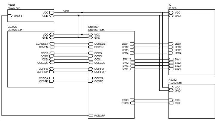
CIRCUIT DIAGRAM:
Fig 3 : Circuit diagram
In that Fig.3 The sensors are used for the weather parameters are LM35 for the temperature sensing, HIH3160 series is used and a short circuit is used for the rain fall sensing is used. The data form this is transmitted through the ADC conversion circuit where the analog data from the parameter transducers are changed to digital form
HUMIDITY
SENSOR
TEMP
SENSOR
A/D
CONVERTER
MICRO-CONTROLLER
RAIN
SENSOR
RELAY
DRIVER
Zigbee
by the circuit used. there are different sensors which connected with ADC and ADC is connected with microcontroller which is seen on the LCD and the PC.
MICROCONTROLLER:
The AT89S52 is a low-power, high-performance CMOS 8-bit microcontroller. The in-system programmable Flash memory is 8K byte. Atmel’s high-density non-volatile memory technology is used to manufacture this microcontroller and is compatible with the industry-standard 80C51 instruction set and pin-out. Using conventional non volatile memory programmer or on-chip Flash the program memory can be reprogrammed. Atmel AT89S52 is a powerful microcontroller which provides a highly-flexible and cost-effective solution too many embedded control applications as it combines a versatile 8 bit CPU with in-system programmable Flash on a monolithic chip.
The specifications of AT89S52 are a flash memory of 8K bytes, RAM of 256 bytes, 32 input and output lines(I/O lines), watchdog timer, two data pointers, three 16 bit counters, an architecture of six - vector two level interrupt, a duplex serial port, on-chip oscillator and on board circuitry clock. For further insights in AT89S52, it is designed with operation down to zero frequency by static logic and has two different power saving modes. It also has an idle mode, which stops the CPU which enables the RAM, serial port, counters and interrupt system to function. The power down mode conserve the RAM contents by freezing the oscillator and disabling chip functions until the hardware reset or next interrupt.
In this paper microcontroller is interfaced to ADC0808, ZIGBEE module, and relay driver. The analog to digital convertor converts the analog data collected from the temperature sensors into digital format and gives it to the microcontroller. The ZIGBEE module in the RTU sends this data from microcontroller to MTU. The information obtained from the MTU is again given to microcontroller and then to the relay driver to drive the output.
ZIGBEE Module:
ZIGBEE is a device that is based on IEEE 802.15.4 standard as shown in fig 4. ZIGBEE is into the class of wireless domain like GSM and RF technology. As it is wireless, the maintenance of the wires and the cost will be effectively reduced compared to the other wired technologies. ZIGBEE also provides a certain bit ON/OFF level to the receiver side so that the same data is transmitted from the transmitter as the wired technologies provide. Thus ZIGBEE replaces the connecting wires and provides a wireless communication.
Fig. 4 ZIGBEE module
Fig 5: Basic model of Zigbee
IV. VISUAL BASIC FOR SCADA
VISUAL BASIC is used to develop SCADA software. On start-up, Visual Basic 6.0 will display the following dialog box as shown in figure.6. One can choose to start a new project, open an existing project or select a list of recently opened programs. A project is a group of files that makes an application. Various types of applications we can be created, however, we will concentrate on creating Standard EXE programs (EXE means executable program). Click on the Standard EXE icon to enter the VB programming environment.
V
.
EXPERIMENTAL RESULTSHARDWARE RESULTS
1) TEMPERATURE
Table.1: Temperature measurement w.r.t time
As shown in Table 1, the weather has been observed in 0C on the LCD display in winter and summer season respectively. In Winter season the climate condition is cold therefore the measured temperature is found 230C to 250C. During summer season the climate condition is hot therefore the measured temperature is found 390C to 410C.
2) RELATIVE HUMIDITY
Table.2: Relative humidity (%) w.r.t time
As shown in Table 2, the relative humidity has been observed in % on the LCD display. A 12 hour analysis is made from 9 AM to 9 PM. It is noted that Relative humidity found to be higher side during morning and evening time. On the other hand it seems to be low during afternoon time.
DATE TIME TEMPERATURE DATE TIME TEMPERATURE
10-5-2016 11:13:12 AM 450C 29-11-2015 15:46:24 AM 24 0C
10-5-2016 11:13:34 AM 430C 29-11-2015 15:46:30 AM 230C
10-5-2016 11:14:21 AM 410C 29-11-2015 15:46:35 AM 230C
10-5-2016 11:14:48 AM 400C 29-11-2015 15:46:41 AM 230C
10-5-2016 11:15:15 AM 400C 29-11-2015 15:46:47 AM 230C
10-5-2016 11:15:32 AM 400C 29-11-2015 15:46:53 AM 240C
10-5-2016 11:15:52 AM 400C 29-11-2015 15:46:59 AM 240C
10-5-2016 11:16:08 AM 390C 29-11-2015 15:47:04 AM 250C
10-5-2016 11:16:21 AM 390C 29-11-2015 15:47:10 AM 25 0C
10-5-2016 11:16:35 AM 390C 29-11-2015 15:47:16 AM 250C
10-5-2016 11:16:48 AM 390C 29-11-2015 15:47:22 AM 240C
10-5-2016 11:16:56 AM 390C 29-11-2015 15:47:28 AM 240C
DATE TIME RELATIVE
HUMIDITY (%)
DATE TIME RELATIVE
HUMIDITY (%)
10-05-2016 9:13:15 AM 55 29-11-2015 9:13:15 AM 85
10-05-2016 10:13:28 AM 52 29-11-2015 10:10:20 AM 82
10-05-2016 11:13:52 AM 50 29-11-2015 11:22:52 AM 78
10-05-2016 12:14:28 PM 47 29-11-2015 12:15:22 PM 68
10-05-2016 1:14:54 PM 45 29-11-2015 1:15:55 PM 65
10-05-2016 2:15:08 PM 40 29-11-2015 2:15:08 PM 63
10-05-2016 3:15:22 PM 38 29-11-2015 3:25:20 PM 62
10-05-2016 4:15:45 PM 39 29-11-2015 4:35:45 PM 65
10-05-2016 5:16:05 PM 41 29-11-2015 5:26:05 PM 72
10-05-2016 6:16:18 PM 42 29-11-2015 6:36:20 PM 76
10-05-2016 7:16:24 PM 46 29-11-2015 7:20:20 PM 81
SOFTWARE RESULTS
The software results are obtained from visual basic. In that the temperature range is set from 10 0C to 40 0C. If the temperature is within that range then software output shows green signal.
VI. CONCLUSION
Data acquisition and data logging is the most important aspect of any measurement system. Data acquisition uses data acquisition hardware and a computing device to acquire real time data from the field and display it in monitor. Data acquisition can be PC based wirelesss. In PC based data acquisition, the PC is used where in wireless data acquisition transmitter and receiver is used to acquire the data.This project develops a hardware prototype of PC based and wireless based data acquisition system for a greenhouse applications. Different physical parameters like temperature, Humidity, Rainfall ,Light intensity are acquired and logged. Wireless data acquisition system is developed to monitor temperature in wireless domain.
This project can be used in industries as well as domestic applications wherever automation is needed. Further this project can be upgraded using advanced technologies, to control the voltage, current and other factors like speed, intensity etc., of the desired machines.
REFERENCES
[1] Dr.Aditya Goel & Ravi Shankar mishra “Remote Data Acquisition Using Wireless –Scada System” International Journal of Engineering(IJE),Volume(3): Issue (1)pp-58,2009.
[2] Subhransu Padhee, Yaduvir Singh “Data Logging and Supervisory Control of Process Using LabVIEW”,Proc. Of the IEEE Students Tech. Symp.,pp.329-334,Jan2011.
[3] Izzat Din Abdul Aziz, Mohd Hilmi Hasan, Mohd Jimmy Ismail, Mazlina Mehat and Nazleeni Samiha Haroon, “Remote monitoring in agricultural green house using wireless sensor and short message service (SMS),” InternationalJournalofEngineering&Technology, 9(9), pp. 35- 43, 2009.
[4] SachinShinde; RohitJethmalani; PankajSawant; Adnan Ansari; “SCADA Based Monitoring and Controlling Using ZIGBEE” IJCSI Technology Volume (3),Issue 3,Year 2012 Pages(3958-3961).
[7] Kratika Sharma, Hemendra Shrimali, Jaideep Sing Hada, Abhishek Chattri, “Data acquisition and supervisory control system for environmental parameters in green house,” InternationalJournalofEngineeringTrendsandTechnology, 3(5), pp. 595-600, 2012
[8] NeerajKhera ;SumitBalguvhar; “Design of microcontroller based wireless SCADA system for real time data” process of the international conference in computer science and electronics engineering 2012, Publication Year:10dec. 2012 , Page(s): 978– 981.
[9] Mollah,M.B; Islam,s.s “Towards IEEE 802.22 based SCADA System for future distributed system”. informatics electronics & vision international conference year 2012 pages (1075-1080).