Multi Disciplinary Design Optimization
Y V Kishore Kumar Nethala
1, K Babitha
2, G Sravanthi
3Assistant professor, Department of Aeronautical Engineering, IARE College, Hyderabad, India1
Assistant professor, Department of Aeronautical Engineering, IARE College, Hyderabad, India2
Assistant professor, Department of Aeronautical Engineering, IARE College , Hyderabad, India3
ABSTRACT: To find an optimal design solution for Blended Wing Aircraft with desired geometrical model by using
MDO framework . The optimization is carried out in two disciplines viz.., aerodynamics and propulsion. The Range, Aspect ratio and Cruise Thrust of the aircraft are expected to be maximised and the maximum Specific Fuel Consumption is expected to be minimised with in the given constraints.
The mode FRONTIER is a MDO framework that serves as a platform for the optimization process. The optimization framework mode FRONTIER is multidisciplinary and multi-objective software written to allow easy coupling to any computer aided engineering (CAE) tool is used in optimization process where it represents the set of best solutions possible.
KEYWORDS: Blended-wing-body, Multidisciplinary design optimization, Aspect Ratio, Wing reference area ,Wing
span, Root chord
I. INTRODUCTION
Multi-disciplinary design optimization (MDO) is a field of engineering that uses optimization methods to solve design problems incorporating a number of disciplines. As defined by Carlo Polono, MDO is “the art of finding the best compromise”. It is also known as multidisciplinary optimization and multidisciplinary system design optimization (MSDO). MDO allows designers to incorporate all relevant disciplines simultaneously. The optimum of the simultaneous problem is superior to the design found by optimizing each discipline sequentially, since it can exploit the interactions between the disciplines. However, including all disciplines simultaneously significantly increases the complexity of the problem. These techniques have been used in a number of fields, including automobile design, naval architecture, electronics, computers, and electricity distribution. However, the largest numbers of applications have been in the field of aerospace engineering, such as aircraft and spacecraft design. For example, the proposed Boeing blended wing body (BWB) aircraft concept has used MDO extensively in the conceptual and preliminary design stages. The disciplines considered in the BWB design are aerodynamics, structural analysis, propulsion, control theory, and economics.
CONCEPTUAL DESIGN OF BLENDED WING BODY
For conventional large transport aircraft, a substantial knowledge base exists for best practice in the wing design for transonic performance. Recently non-conventional aircraft designs, such as the blended wing body (BWB) aircraft, have been proposed based on earlier flying wing designs for revolutionary improvement for future air transportation. Conceptually, the main aerodynamic advantages of the new BWB design are its lower wetted area to volume ratio and lower interference drag as compared to the conventional aircraft. Indeed, an increase in (L/D) max of about 20% over the
conventional design has been estimated for the blended wing body.
Figure 1 Basic design of the BWB fuselage
There are some key concepts to note about the design of the BWB:
1. The BWB is a tailless aircraft: Because of the disc-shaped nature of the fuselage, the BWB does not have a tail. As a result, the BWB does not have a rudder.
2. The engine location of the BWB: Another important characteristic of the BWB design is position of the engines, are located at the aft sections of the plane. Because of the weight and balance considerations of the plane, the engines needed to be place at the rear of the plane. Additionally, with the engines at the rear of the plane, the fuselage can serve as an inlet for the intake of air.
3. Control surfaces: The control surfaces of the wing are located along the leading and trailing edges of the wing and on the winglets. The number of control surfaces can vary from 14 to 20 depending on the BWB design.
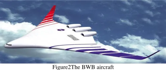
Figure2The BWB aircraft
The BWB has several distinct advantages over the conventional tube aircraft. Some of these advantages are outlined below:
1. Higher fuel efficiency: Initial testing of the BWB aircraft has indicated that it can have up to a 27% reduction in fuel burn during flight.
3. Lower takeoff weight: Early design concepts have determined that the BWB can have up to a 15% reduction of take-off weight when compared to the conventional baseline .
4. Lower wetted surface area: The compact design results in a total wetted difference of 14,300 ft2, a 33% reduction in wetted surface area. This difference implies a substantial improvement in aerodynamic efficiency .
5. Commonality: One of the greatest advantages of the BWB is commonality of size and of application . Firstly, the commonality of the components of the airplane will allow it the payload of the airplane to be varied at little cost. For the 250, 350, and 450 – passenger capacity of the BWB, many components are interchangeable. This interchangeability serves to drive down the cost of the aircraft. Secondly, commonality of function allows the BWB to be used in many applications, both military and civilian. The BWB can be modified to be used as a freighter, troop transport, tanker, and stand-off bomber in addition to its function as a commercial airliner.
II. PROBLEM STATEMENT
AIM:
To find an optimal design solution for Blended Wing Aircraft by MDO framework
The optimization is carried out in two disciplines viz.., aerodynamics and propulsion. The Range, Aspect ratio and Cruise Thrust of the aircraft are expected to be maximised and Maximum Specific Fuel Consumption is expected to minimised with in the given constraints.
Discipline - Propulsion
The optimization problem statement:
Minimize: f(x) = SFCmax
Maximize: f(x) = Tcruise
By varying: x = Bypass ratio Constraints: BPR
Objectives: Maximum specific fuel consumption, Thrust at cruise Possible DOE algorithm:Sobol
Optimizer (scheduler): Base Scheduler – MOGA (Multi - Objective Genetic Algorithm) Discipline – Aerodynamics
The optimization problem statement: Minimize: f(x) = CD
Maximize : f(x) = Range
By varying : x = aerodynamic shape i.e ., Aspect Ratio
Constraints: Aspect Ratio
Objective function: Coefficient of drag, Range. Possible DOE algorithm: Sobol
Optimizer (Scheduler): Base Scheduler – MOGA (Multi - Objective Genetic Algorithm) Given data:
Based on the aerodynamic calculation following Ref-2, the aerodynamic characteristics of the aircraft are:
CD0 (0.85 M) = 0.0059
CL (cruise at 0.85 M) = 0.2045
CDi (0.85 M) = 0.0023
CL/CD (0.85 M) = 24.91
Taper ratio = 0.33, it’s enough to minimize the induced drag,
Swept at c/4 = 300 (Swept at LE = 340, Swept at t/cmax = 280), it’s able to delay mach drag divergence,
Incidence angle = 30, it’s able to give enough CL at take off, cruise and landing,
Maximum thrust = 17500 lbs
Maximum climb thrust = 3740 lbs
Bypass ratio = 4.43
Cruise specific fuel consumption = 0.37 lb/lbT/hr
Range = 14816 km Wing Geometry:
Wing reference area (S) = 300.31 m2
Wing span (b) = 42.45 m
Root chord (cr) = 10.88 m
Aspect Ratio (A) = 6
Optimization is the key to reach this goal, achievable through integration with multiple calculation tools and explicable by effective post-processing tools. The MDO framework is provided with several Direct Integration nodes for coupling with third-party software packages. Here in this thesis, direct integration is not available for the DOS code and hence interface scripting in Java Integration Calculator is done for this purpose. The interfacing is a very complex task and involves in any one scripting language, such as Python or Visual Basic or MS DOS script. This involves a feasible integration with the code and hence can be used in the optimization of the project. The workflow component contains the Workflow editor, the graphical tool used to describe the multi-disciplinary, multi-objective problem to solve. The workflow specifies how to define and compute all the main design measures. This tool can be used,
To describe inputs (or parameters) that defines a design, setting their legal boundaries.
To describe the resources that should be used to compute the outputs (or measures).
Indicate the goals of the process that determine the business effectiveness of the design.
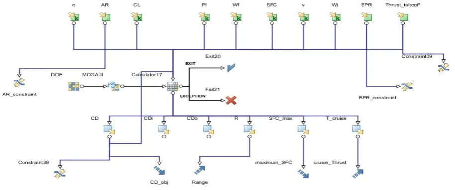
The input variables, output variables, constraints, transfer variables, project files are declared and the scheduler is also set using the options available in the workflow window as in the figure below. The inputs are all declared and the directory locations are specified in the script files and hence they follow the script and are directed to follow the commands as in the script files. The commands that are specified by the user are in relation to the steps that the user wishes to operate for the analysis to take place.
Input variable nodes : 1. Wing Span (b) 2.Wing Area (S)
3. Oswald's Coefficient (e) 4. Aspect Ratio
5. Coefficient of Lift (CL)
6. Initial Weight (Wi) 7. Final Weight (Wf) 8. Bypass Ratio (BPR) 9. Free Stream Velocity (v)
10. Take-off Thrust (Thrust take-off) 11. Specific Fuel Consumption (SFC)
Variable Lower Bound Upper Bound Base
Aspect Ratio 4 14 26
Bypass Ratio 2 5 61
Take-off Thrust 20000 25000 250
Table 1 Variable Bounds
Output Variable nodes 1. Coefficient of Drag (CD)
2. Coefficient of Free stream Drag (CD,O)
3. Coefficient of Induced Drag (CD,I)
4. Range (R)
5. Maximum Specific Fuel Consumption (SFCmax)
6. Cruise Thrust (Tcruise)
Constraint Nodes: Constraint is a condition that must be satisfied in order for the design to be feasible. In the
Work flow the following are constrained.
1. Aspect Ratio : For the aircraft to produce minimum induced drag, the Aspect ratio has to be higher. Here, it is constrained to less than 12 : 1.
2. Take offThrust : It is constrained to greater than the experimental value of 20955.0 kg. 3. Bypass Ratio : It is constrained to less than the experimental value of 4.43.
4. Coefficient of Drag : The output value is constrained to a maximum of the experimental value of 0.009
Objective Nodes : (maximize) (minimize)
It represents the numerical value that is to be maximized or minimized. They are: 1. Coefficient of Drag
2. Range
3. Maximum specific Fuel Consumption 4. Cruise Thrust
Process Flow or Logic Flow :
Figure 4 Logic flow
Design of experiments (DOE) : The is the starting node for project, and is used to define the Design
Of Experiments algorithm to be used to create the initial set of designs to be evaluated. Accordingly, one, and only one, such node must exists in any legal Work Flow. This node always appears in conjunction with the scheduler node, which actually determines which DOE designs will be evaluated..
Scheduler Node:The is the one which designs need to be evaluated. The strategy used to select
the DOE designs of interest, and to generate new designs, is determined by the scheduling algorithm selected. The scheduler node is MOGA-II Scheduler based on Multi Objective Genetic Algorithm (MOGA) designed for fast Pareto convergence.
Main features:
1) Supports geographical selection and directional cross-over. 2) Implements Elitism for multiobjective search.
3) Enforces user defined constraints by objective function penalization. 4) Allows Generational or Steady State evolution.
5) Allows concurrent evaluation of independent individuals.
The N (num. of individuals) entries in the DOE table are used as the problem's initial population. Each input variable base must be different from zero, since MOGA-II works only with discrete variables.
Parameters:
Number of Generations [,1,5000] - 20
Probability of Directional Cross-Over [0.0,1.0] - 0.5 Probability of Selection [0.0,1.0] - 0.05
Probability of Mutation [0.0,1.0] - 0.1
Application Node : The Scheduler node output connector can be connected to one, and only one, Application Node process input connector. The Calculator Node stores and configures scripts in JavaScript syntax. During the run phase the node will access directly the internal JavaScript interpreter to execute the user defined script.
Figure 5 External Script node
It has both process and data flow, input and output connectors. The scheduler output connects to the process input connector and if the processing of the user script completes without any error the calculator node exits with the EXIT
Figure 6 Process Connector
III.RESULTS AND DISCUSSION
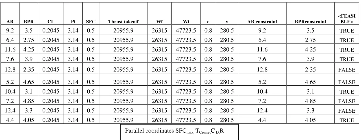
DOETABLE ,SHOWING FEASIBLE AND UNFEASIBLE DESIGNS
AR BPR CL Pi SFC Thrust takeoff Wf Wi e v AR constraint BPRconstraint
<FEASI BLE>
9.2 3.5 0.2045 3.14 0.5 20955.9 26315 47723.5 0.8 280.5 9.2 3.5 TRUE
6.4 2.75 0.2045 3.14 0.5 20955.9 26315 47723.5 0.8 280.5 6.4 2.75 TRUE
11.6 4.25 0.2045 3.14 0.5 20955.9 26315 47723.5 0.8 280.5 11.6 4.25 TRUE
7.6 3.9 0.2045 3.14 0.5 20955.9 26315 47723.5 0.8 280.5 7.6 3.9 TRUE
12.8 2.35 0.2045 3.14 0.5 20955.9 26315 47723.5 0.8 280.5 12.8 2.35 FALSE
5.2 4.65 0.2045 3.14 0.5 20955.9 26315 47723.5 0.8 280.5 5.2 4.65 FALSE
10.4 3.1 0.2045 3.14 0.5 20955.9 26315 47723.5 0.8 280.5 10.4 3.1 TRUE
7.2 4.85 0.2045 3.14 0.5 20955.9 26315 47723.5 0.8 280.5 7.2 4.85 FALSE
12.4 3.3 0.2045 3.14 0.5 20955.9 26315 47723.5 0.8 280.5 12.4 3.3 FALSE
4.4 4.05 0.2045 3.14 0.5 20955.9 26315 47723.5 0.8 280.5 4.4 4.05 TRUE
IV.CONCLUSIONS
The best optimized design values are obtained for design ID: 2
Variables Optimized Values
Coefficient of Drag 0.007335
Aspect Ratio 11.6
Range 9310.429
Maximum Specific Fuel Consumption 0.36
Cruise Thrust 3697.89
From Scatter chart of Coefficient of Drag Vs Range, it is to be noted that a quadratic relationship exists between these two objectives.
From scatter chart of maximum specific fuel consumption Vs thrust at cruise, a quadratic relationship is seen between them.
As SFCmax is decreased, thrust at cruise is increased.
REFERENCES
1. Azki Hakim, Mahesa Akbar and Dr.TaufiqMulyanto, Conceptual Design of Blended-Wing-Body Business Jet, AIAA paper.
3. Kevin R. Bradley, A sizing Methodology for the Conceptual Design of Blended-Wing-Body Transports, NASA/CR-2004-213016 , September 2004.
4. Daniel P. Raymer, Enhancing Aircraft Conceptual Design Using Multidisciplinary Optimization, Doctoral Thesis, Report 2002-2, May 2002, ISBN 91-7283-259-2.
5. ESTECO modeFRONTIER, User’s Manual.
6. Andy J. Keane &Prasanth B. Nair, Computational Approach for Aerospace Design, The Pursuit of Excellence, John Wiley & Sons, Ltd, England. 7. W.H. Mason and B. Grossman, MDO of a Blended-Wing-Body Transport Aircraft with Distributed Propulsion, AIAA's 3rd Annual Aviation Technology, Integration, and Operations (ATIO) Technical Forum, 17-19 November 2003
8. R. H. Leibeck, Design of the Blended Wing Body Subsonic Transport, The Boeing Company's Journal of Aircraft, Vol.41, No. 1, January-February 2004.
9. Sean Wakayama, Multidisciplinary Design Optimization of the Blended-Wing-Body, The Boeing Company, A98-39885, AIAA-98-4938, 1998. 10. Patrick Chang, Aditya Shah, MukulSinghee, Parameterization of the Geometry of a Blended-Wing-Body Morphing Wing, ME 6104: Fundamentals of Computer-Aided Design, Project at Systems Realization Laboratory, 28/4/2009.
11. SrinivasKodiyalam&JaroslawSobieszczanski-Sobieski, Multidisciplinary Design Optimization – Some Formal Methods, Framework Requirements, and Application to Vehicle Design, Int. J. Vehicle Design (Special Issue), pp. 3–22, 2001.
12. Wikipedia Site: http://en.wikipedia.org/wiki/Multidisciplinary_design_optimization. 13. ESTECO Site: http://www.esteco.com/home/mode_frontier/mode_frontier.html.