ABSTRACT
ELECHITAYA SURESH, SANATH KUMAR. System Level Design of a Turbo
De-coder for Communication Systems. (Under the direction of Professor Winser E
Alexander).
Advancements in silicon technology have heralded an increase in device densities and consequently design complexity. The increasing complexity of modern System on
a Chip designs dictates a cohesive methodology for co-simulation at both high and
low abstraction levels, effective design space exploration, system integration and high simulation speeds. A single unified design flow would avoid many of the shortcomings
faced by the traditional RTL approach to design and verification.
This thesis investigated a SystemCr based design methodology to model complex
digital systems at multiple levels of abstraction. The SystemC language, which is a
C++ class library, is a multi-paradigm language for hardware design and verification.
The capabilities of SystemC in supporting timed behavior, hierarchy, concurrency,
and creation of fast executable specifications of the target design have been
demon-strated in our work. It was our aim to clearly represent the ability of the proposed
design flow to capture and validate the details of a design at the system level of abstraction, starting with an abstract Functional Verification level, working our way
through to the Cycle Accurate level. This was exemplified by the design of a complex
Iterative Turbo Decoder algorithm as a prototype system to test our design flow. We compared the decoder behavior at the system level using SystemC and at the RTL
us-ing Verilog 2001r. We found that simulations performed at the system level executed
much faster than simulations at the RTL. We used the system level design to estimate round-off errors without having to refine our design to the RTL. We demonstrated
the ease of architectural exploration using SystemC by implementing two classes of
interleavers for the Turbo Decoder: the Pseudo Random and the 3GPP Standard Interleaver. We also performed a detailed power and area analysis on the RTL model
using the SSHAFT tool. We established a single language framework that allows
System Level Design of a Turbo Decoder for Communication Systems
by
Sanath Kumar Elechitaya Suresh
A thesis submitted to the Graduate Faculty of North Carolina State University
in partial fulfillment of the requirements for the Degree of
Master of Science
Electrical Engineering
Raleigh
2005
Approved By:
Dr. J. K. Townsend Dr. William Rhett Davis
To
Biography
Sanath Kumar was born on January 8th 1981 in Mangalore, India. He received his
Bachelor’s degree in Electronics and Communications Engineering from R.V.College
of Engineering, Visweswariah Technological University, Bangalore, India in 2002. He
worked in Philips India Ltd. as a Graduate Engineer between Oct 2002 and August 2003. In the fall of 2003, he enrolled in the Electrical and Computer Engineering
Department at North Carolina State University to pursue a Master of Science degree. Since then, he has been a part of the Hi-Performance DSP group headed by Dr.
Acknowledgements
This work would not have been possible without the continuous support and guidance of my advisor Professor Winser Alexander. It has been a great learning experience
this past year and I am grateful for the opportunity to be able to work for him. His
knowledge and incredible patience never ceases to make me wonder. I also wish to
thank the other members of my thesis committee, Professor Rhett Davis and Professor Keith Townsend for their invaluable guidance.
I wish to express my sincere thanks to the High Performance (HiPer) DSP Research
group for creating an environment that has been fabulous for research and fun. Ad-ditional thanks to Ramsey Hourani and Senanu Ocloo for their unconAd-ditional help
throughout my stay in the group. The encouragement and moral support extended
by all members of the group through good and hard times cannot be described in words.
Special thanks to Ravi Jenkal for his input, criticism and witty remarks! I greatly
appreciate his help in the completion of this work. I also wish to thank Viren Patel
for his steady support and friendship.
Above all, I wish to thank my father Suresh, my mother Savitha and my sister
Saritha - their unwavering love and affection can only be matched by my gratitude
towards them for what I am today. Mom has been a great friend, mentor and an infinite source of inspiration to me, while Dad’s words of wisdom have constantly
guided me through the right path in life. It is to my sister Saritha, however, that I
Contents
List of Tables vii
List of Figures viii
1 Introduction 1
1.1 Iterative Turbo Decoding. . . 4
1.2 System Level Implementation of Turbo Codes . . . 6
1.3 Thesis Outline . . . 6
2 System Design using SystemC 8 2.1 SystemC V2.0 . . . 11
2.2 Abstraction Levels in System Design . . . 14
2.3 SystemC and Verilog 2000 . . . 22
3 Fundamentals of Turbo Decoding 24 3.1 Error Correction Codes . . . 25
3.2 Block Codes . . . 25
3.3 Convolutional Codes . . . 26
3.3.1 Recursive Systematic Convolutional (RSC) Encoder . . . 28
3.4 Turbo Codes. . . 28
3.4.1 Turbo Code Internal Interleaver . . . 31
3.5 Turbo Decoding . . . 32
3.5.1 Turbo Decoder Operation . . . 33
3.5.2 Maximum A Posteriori (MAP) Algorithm . . . 36
3.5.3 Max-Log-MAP and Log-MAP Algorithms . . . 40
3.6 Performance and Results . . . 45
4 Turbo Decoder System Design 47 4.1 SystemC Functional Model . . . 48
CONTENTS
4.2.1 Cycle Accurate SystemC Model . . . 53
4.2.2 Turbo Decoder Behavioral Model . . . 55
4.3 Turbo Decoder using 3GPP Interleaver . . . 60
4.3.1 Turbo Code Interleaver (3GPP Standard) . . . 60
4.3.2 Inter-row and Intra-row Permutation . . . 62
4.4 System Design of the Turbo Decoder using 3GPP Interleaver . . . 66
4.5 Conclusion . . . 67
5 RTL Model of the Turbo Decoder 68 5.1 Forward and Backward Path Metric Calculations . . . 69
5.2 SISO Decoder . . . 73
5.3 Final Turbo Decoder Design . . . 76
5.4 RTL Schematic Representation . . . 80
5.5 Memory Organization . . . 85
5.5.1 Alpha Storage and Interleaver Memory . . . 85
6 Testing and Results 88 6.1 Turbo Decoder Testing . . . 88
6.2 Testing RTL Model of the Turbo Decoder . . . 90
6.3 SystemC and RTL Simulation Times . . . 90
6.4 Effects of Scaling and Varying Word Lengths . . . 92
6.5 Simulation Clock Cycles . . . 94
6.6 Area and Power Trends . . . 95
6.6.1 Alpha RAM . . . 95
6.6.2 Interleaver RAM . . . 97
6.6.3 Turbo Decoder Logic Area . . . 99
6.7 Power Results . . . 101
6.8 Design Time . . . 102
6.9 Synthesis Results and Conclusion . . . 102
7 Conclusions and Future Work 104 7.1 Conclusions . . . 104
7.2 Future Work . . . 105
List of Tables
4.1 Inter-row Permutation Pattern for the Turbo Code Interleaver . . . . 63
4.2 Table of Interleaver Parameters . . . 64
6.1 Total number of bits for Alpha Storage . . . 97
6.2 Total number of bits for Interleaver Memory . . . 99
6.3 Comparison of Design Times . . . 102
List of Figures
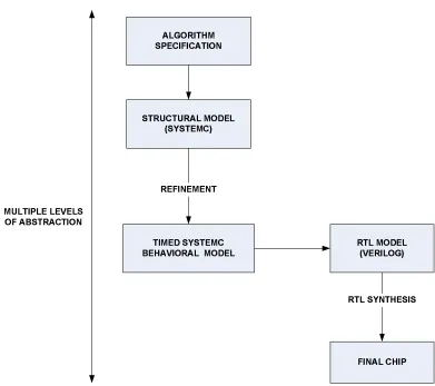
1.1 Generic SystemC based Design Flow . . . 3
1.2 Turbo Encoder Block Diagram. . . 4
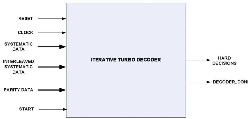
1.3 Iterative Turbo Decoder Block Diagram. . . 5
2.1 A generic SystemC design flow . . . 12
2.2 SystemC design methodology . . . 17
3.1 A Rate 13 convolutional encoder . . . 27
3.2 Trellis Diagram for the Rate 1/3 convolutional encoder . . . 27
3.3 Structure of a Rate 1/3 UMTS Turbo Encoder . . . 29
3.4 Block Diagram of a SISO Decoder . . . 33
3.5 Channel Encoding and Decoding Model over an AWGN channel . . . 34
3.6 Block Diagram Schematic of an Iterative Turbo Decoder . . . 35
3.7 Graphical representation of the forward and backward recursion . . . 38
3.8 BER vs. SNR curve for different frame lengths . . . 45
4.1 Block Diagram of the Log-MAP SISO Decoder . . . 48
4.2 SystemC Functional Level Model of the SISO Decoder . . . 50
4.3 Structure of the PN generator for functional interleaving . . . 51
4.4 Structural Model of the Iterative Turbo Decoder . . . 53
4.5 SC CTHREAD Communication Between Modules . . . 54
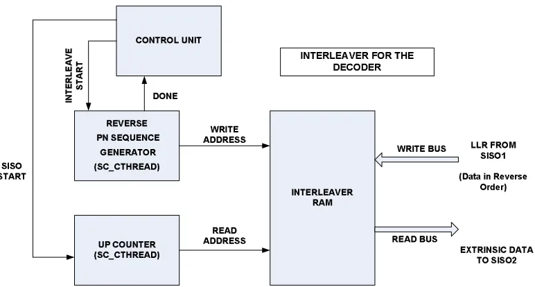
4.6 Structure of the PN generator for Interleaving at the Decoder . . . . 56
4.7 Architecture of the Interleaver at the Decoder . . . 57
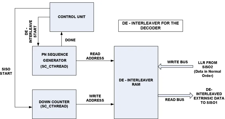
4.8 Architecture of the De-Interleaver at the Decoder . . . 58
4.9 Timed Iterative Turbo Decoder Module . . . 59
4.10 Structural Model of Turbo Decoder using 3GPP Interleaver . . . 65
5.1 Block Diagram of the Iterative Turbo Decoder . . . 68
5.2 Implementation of the Forward/Backward Path Metric Calculation . 70 5.3 Block Diagram of the SISO Decoder. . . 72
LIST OF FIGURES
5.5 Verilog Model of the Iterative Turbo Decoder . . . 77
5.6 State Control Machine for the Iterative Turbo Decoder . . . 79
5.7 RTL Model of the Alpha Generation Unit . . . 80
5.8 RTL Model of the Beta Generation Unit . . . 81
5.9 RTL Model of the LLR Generation Unit . . . 82
5.10 RTL Model of the SISO Decoder . . . 83
5.11 RTL Model of the Iterative Turbo Decoder . . . 84
5.12 Memory Organization for the Interleaver RAM . . . 86
6.1 BER plot of the Turbo Decoder using the 3GPP Standard Interleaver 89 6.2 Simulation times using the Pseudo Random Interleaver . . . 91
6.3 Simulation times using the 3GPP Standard Interleaver . . . 91
6.4 Comparison of SystemC and RTL simulation times . . . 92
6.5 BER plot for different word lengths and scaling factors . . . 93
6.6 Plot of the difference in decoding latencies using SystemC and Verilog 95 6.7 Area of the Alpha RAM for different Bit Widths. . . 96
6.8 Area of Alpha RAM for different Frame Lengths . . . 96
6.9 Area of the Interleaver RAM for different Bit Widths . . . 98
6.10 Area of the Interleaver RAM for different Frame Lengths . . . 98
6.11 Area of the Turbo Decoder Logic for different Bit Widths . . . 100
Chapter 1
Introduction
Rapid advancements in silicon technology have revolutionized system design and
complexity. Designers have moved towards higher levels of abstraction and design languages in order to manage this continuously increasing complexity and a dynamic
marketing trend. The traditional RTL approach to design and verification flows no
longer proves to be adequate for modeling systems. It therefore becomes necessary to
develop a single unified environment that would solve many of the shortcomings of the
traditional design approach. SystemCris a newly emerging standard which facilitates
co-design and verification within a single modeling platform. The single language framework facilitates easy refinement of functional level models into implementation.
SystemC is a C++ based modeling language supporting design abstractions at the
Register-Transfer, behavior and system levels. It consists of a C++ class library and
a simulation kernel. The SystemC language is an attempt towards standardization of a C/C++ based design methodology and is being supported by the Open
Sys-temC Initiative (OSCI). OSCI is a conglomerate of a wide range of semiconductor
companies, Intellectual Property (IP) providers, embedded software developers and design automation tool vendors. The advantages of SystemC include the ability for
estab-Chapter 1 Introduction
lishment of a common design environment consisting of C++ libraries, models and tools and the ability to reuse test benches across multiple levels of design
abstrac-tion. SystemC also offers good design-space exploration of functional specification
and architectural implementation alternatives. The SystemC model can be effectively used to create cycle-accurate models of software algorithms, hardware architectures
and the interfaces of the System On a Chip (SoC) or System designs. The SystemC
class library provides the necessary constructs to model system architecture including
hardware timing and concurrency that are absent in standard C++ [1].
Modeling systems using SystemC has multiple advantages. The design can be
in-crementally refined with the addition of hardware and timing constructs to arrive at
the final target architecture. SystemC ensures a smooth flow in capturing design de-tails at multiple abstraction levels starting with an algorithmic level implementation
that is used to verify the functionality of the system up to a cycle-accurate design.
SystemC programming offers higher productivity in terms of fewer number of code lines, ease of writing and increased simulation speeds than traditional modeling
en-vironments, while retaining the ability to model hardware components at a detailed
level. Architectural exploration and evaluation, and system integration require the modeling of systems at the behavioral level using concurrent software. SystemC
fa-cilitates this modeling style by providing event objects and dynamic sensitivity. Most
hardware descriptive languages offer static sensitivity wherein the process activates in response to an event on the signal it is sensitive to. In addition to static sensitivity,
SystemC also provides dynamic sensitivity by waiting explicitly for events that are
determined at run-time. SystemC supports processes to model combinational logic
as well as synchronous design. The most generic System Design flow is illustrated in
Figure1.1
The development of a design methodology that bridges the gap between functional
level implementation and RTL modeling has captured the attention of researchers worldwide. Extensive work has been done in the area of hardware/software
Chapter 1 Introduction
Figure 1.1: Generic SystemC based Design Flow
the vast amount of interest generated in System design at high abstraction levels, there has not been a comprehensive methodology. The RTL design flow does not
al-low for effective design-space exploration, does not address system level partitioning and most importantly requires high design time, high development efforts and longer
time-to-market for complex systems. The principal aim of this work was to establish
a design paradigm that would provide for hardware/software co-simulation, decrease
simulation times and enable efficient architectural explorations using SystemC as the modeling platform. We develop an Iterative Turbo Decoder at the system level as
well as at RTL to define this design methodology. We aim to characterize the design
1.1 Iterative Turbo Decoding
and tested for bit error rate (BER) performance, latency, round off effects and design tradeoffs at a higher abstraction level.
1.1
Iterative Turbo Decoding
Turbo Codes are a class of Forward Error Correction codes that have found
widespread popularity in modern communication systems. Their introduction by
Berrou et al. [9] opened up a totally new perspective to channel coding theory. An
outstanding error correcting capability coupled with increasing importance of wireless communications created widespread interest in Turbo coding. A Turbo code is the
parallel concatenation of two or more component codes. A generic Turbo encoder is
shown in Figure 1.2.
!"#$
%"&#" ! !' &# "!
# !"% ( # "#
# !"%) # "# !" # "#
Figure 1.2: Turbo Encoder Block Diagram
The encoder consists of two identical rate 1/2 Recursive Systematic Convolutional
(RSC) encoders in parallel. The input data is transmitted to the upper encoder in normal order while it is interleaved before being fed to the lower encoder. The
systematic information for both the encoders are the same and consequently, only one of them needs to be transmitted. Thus the output of the encoder consists of
1.1 Iterative Turbo Decoding
(Parity1 Data) and the parity information from the lower RSC encoder (Parity2
Data). The overall code rate of the parallel concatenated code is therefore, R = 1/3.
The Turbo decoding is performed using a non-optimal Maximum A Posteriori
(MAP) algorithm [9]. The Turbo decoder consists of two elementary decoders in
a serial concatenation scheme. Since soft decoding performs better than hard
decod-ing, the first decoder provides a weighted soft decision in the form of A Posteriori
Probabilities (APPs) to the second decoder. The decoding proceeds in an iterative
fashion as illustrated in Figure 1.3 [35].
*+,-./012/0,
+3.0,40560, /0 +3.0,40560,
-0123/ /012/0,
/0789
+3.0,40560,
:5,/ /01+-+23 -;-.075.+1
/5.5
<5,+.; /5.5
44,
44,
0-.+75.0
-Figure 1.3: Iterative Turbo Decoder Block Diagram
The soft information from the second decoder is fed back to the first decoder, after
the first iteration is complete. This is called the extrinsic or thea priori information.
This information is not available for the first decoder during the first iteration and
is therefore initialized to zero. The soft information is exchanged between the two
1.2 System Level Implementation of Turbo Codes
1.2
System Level Implementation of Turbo Codes
The Turbo decoder can be designed at a higher level of abstraction using SystemC.
The functional model of the decoder tests the algorithm while the behavioral model adds timing to the software design. SystemC supports many hardware design
con-structs to enable design of cycle-accurate models. Modeling systems at increasingly
higher levels of abstraction reduces design times and simulation speeds, and improves
the time to market. The latency of the system can be accurately modeled. This gives a fair amount of information about the final RTL implementation.
The final stage of this design methodology was to develop the cycle-accurate RTL
model. This can be achieved by using a SystemC to Verilogr translator or manually
translating the SystemC design to hardware using Verilog. We have used the latter
approach since there is no translator support for many of the SystemC constructs
used in our design. It was our aim to demonstrate a design flow which greatly eases system level modeling, enhances hardware/software trade-off analysis and achieves
significantly lower design and simulation times by designing at different levels of
abstraction. The final aim was to understand the impact of SystemC on the design of complex systems.
1.3
Thesis Outline
Chapter 2 describes the underlying principles of system level design and the im-portance of SystemC in hardware/software co-design. This chapter also provides a
framework for modeling of complex systems starting with the algorithmic model and
continuing to the RTL. The Iterative Turbo Decoding procedure using the MAP Al-gorithm forms the essence of Chapter 3. This chapter presents, in considerable detail,
the concept of Turbo codes, the Turbo encoder operation and the algorithm for Turbo
decoding that is being used in our design. Chapter 4 outlines the SystemC design of
1.3 Thesis Outline
component decoders and also the overall Turbo decoder have been developed and the various design trade-offs at each level have been discussed in this chapter. We
then proceed to design the RTL for the Turbo Decoder developed earlier. Chapter
5 describes the RTL implementation of the decoder using Verilog 2001. Chapter 6 discusses the results and conclusions drawn from testing the RTL model against the
abstract SystemC model. We conclude the thesis with a brief conclusion and possible
Chapter 2
System Design using SystemC
The ever increasing complexity of modern System-On-Chip designs demands a
co-hesive methodology for architectural evaluation and hardware/software co-verification, which is hardly practicable in the low abstraction levels of implementation models.
These activities are crucial and must be addressed at an early stage in the design cycle
to prevent costly redesign efforts later, that might adversely affect the time to
mar-ket [27]. Intellectual Property (IP) companies have heralded a new age in platform
based design for a number of years since semiconductor integration capacity reached
a point wherein the whole system could be developed on a single die. Such a modeling of systems termed System-On-Chip (SoC), is comprised of several components such
as processors, timers, interrupt controllers, buses, controllers etc. on a single chip. It
is a complete system that would otherwise be available on a chipset. The traditional
RTL approach to design and verification flow often proves inadequate for building such complex systems.
The issues of system level design have attracted considerable attention among
re-searchers. In order to cope with the increasing system complexity, it is necessary to model them at increasingly higher levels of abstraction. It is therefore extremely
rea-Chapter 2 System Design using SystemC
son about the architecture on a much higher level of abstraction. The goal of this methodology is to define a system architecture, which provides sufficient performance,
flexibility and cost efficiency as required by demanding applications like broadband
networking or wireless communications. The methodology also provides capabilities for co-simulating hardware/software and enables reuse of the simulation environment
for functional verification of the target architecture against an abstract architectural
model [24].
Transistor feature sizes have been shrinking each day and advancements in
semi-conductor technology have empowered the development of chips with many millions
of gates. This, however, comes with a trade-off. System design complexity has been
increasing exponentially with a corresponding degradation of simulation speeds and cost efficiency performance. The RTL design flow is not feasible for building large
heterogeneous systems. As complexity grows, an increasing proportion of the
soft-ware and the hardsoft-ware peripherals consists of re-used IP blocks. In view of the above issues, system designers typically use Bus Cycle Accurate (BCA) models written in
high level languages like C/C++ to explore the communication design space. These
models capture all of the design’s bus signals and maintain cycle accuracy, but result in slow simulation speeds for complex designs, even when modeled with high level
languages [28].
Recently, there have been several efforts to use the Transaction Level Modeling
(TLM) paradigm for improving simulation performance in complex digital systems.
TLM is one of the key techniques used in the designing of systems at higher
abstrac-tion levels. This style of modeling systems focuses on exchange of data or events
between two modules or components without giving prominence to the protocol itself that realizes the exchange. The TLM is fast and compact, effectively integrates
hard-ware and softhard-ware models, provides a platform for early softhard-ware development, early
Chapter 2 System Design using SystemC
The foundation for such a methodology is provided by the SystemC library, which is widely considered as the emerging EDA industry standard language for bringing
to-gether system conceptualization and implementation. There is a necessity to perform
different architectural evaluations using a combined SystemC and Verilog IP based framework. The use of SystemC allows us to model systems at higher levels of
ab-stractions and use higher abstract data types, which in turn increases simulation and
design speeds. SystemC V2.0 has been conceived to realize a Transaction Level Model where communication between modules is abstracted from the low-level
implementa-tion details of the Register Transfer Level (RTL). This results in great improvements
in terms of simulation speed and modeling efficiency, and enables the system architect
to create an executable specification of the complete SoC architecture [24].
Simulation speed and modeling efficiency can be improved significantly compared
to the detailed RTL, by modeling the system at a much higher level of abstraction.
This method should enable general algorithmic verification with the possibility of step-by-step refinement at an early stage of the design. Reducing and encapsulating
designs into transactions allows the designer to get a quick perception of the whole
system in terms of its functionality. TLM is just a general approach to hierarchical design methodology. Using a SystemC environment allows for design refinement and
verification with previously used test benches. SystemC promotes a coding style in
which communication is separated from behavior by distinguishing the declaration of an interface from the implementation of its methods (a traditional C++ hallmark).
This is a key feature to promote refinement from one level of abstraction to another.
The following section provides a brief introduction to SystemC, outlining the
2.1 SystemC V2.0
2.1
SystemC V2.0
The SystemC language and modeling platform is gaining momentum as a unified
solution for representing functionality, communication, software and hardware at
var-ious system levels of abstraction [4]. The reason is clear: design complexity demands
very fast executable specifications to validate system concepts, and only C/C++
de-livers adequate levels of abstraction, hardware/software integration, and performance.
SystemC is a C++ class library and allows for effective creation of cycle-accurate models of algorithms and hardware architectures. SystemC results in reduced
simu-lation speeds, faster design validation and greater design space exploration, since it
uses standard C++ development tools. The high abstraction modeling and increased performance enables the creation of software development platforms much sooner in
the design process, allowing software integration and testing at the earliest possible
point. This all adds up to greater parallel development efforts resulting in earlier time-to-market and increased quality of the final product. In addition, SystemC is
open source and supports timed behavior, hierarchy and fixed point representations,
and that makes it an extremely useful tool for designing DSP architectures. More im-portantly, designers are familiar with these languages and its associated development
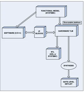
tools. A generic SystemC design methodology is shown in Figure 2.1.
As seen from the design flow block diagram, SystemC is useful in producing a
functional model and an executable of the system for initial testing and verification. Using executable specifications ensures completeness of specification. This also allows
the designer to validate the system function before the actual implementation. The
system can be tested and refined in terms of architecture, bit width accuracy and design performance before moving to the RTL. SystemC also allows for the creation
of reusable IP blocks and Transaction Level models of system design. The power of
the language lies in the fact that it can be used as a common language by system
en-gineers, software and hardware designers [4]. It is also possible to provide additional
libraries to support a particular design methodology. The Master-Slave
2.1 SystemC V2.0
=>?@ABC?DE FCGHE IJKJAHF@L
MD NGO DNH AEF BP
QEC@RJ
NAE IMGEST JKJAHF@L
JK?AM HJBJ JC=AO DNH I@U@VVL
WDAH EHXHE ?HAEBJA HYZ[\]^_`Z a`^]bSTc
Figure 2.1: A generic SystemC design flow
The SystemC class library has been developed by a group of companies forming the
Open SystemC Initiative (OSCI) [3]. The new SystemC Verification Standard [25]
enhances the capabilities for performing basic verification of a design by providing
Application Program Interfaces (APIs) for transaction based verification, constrained
and weighted randomization, exception handling and other verification tasks. Sys-temC test benches can also be used for designs written in Verilog or VHDL to complete
the design flow in a typical design environment.
The development environment of SystemC is the same as that of C/C++, since it
is a C++ class library. It is an object oriented design language that makes full use of data encapsulation and generic programming concepts. It consists of a reference
simulator and class library that may be downloaded from the OSCI website [3]. Also,
con-2.1 SystemC V2.0
sists of a set of module definitions and a top-level function that starts the simulation. Modules are the basic building blocks of a SystemC design. They allow the designer to
partition the system into smaller blocks that can be more easily managed. Modules
contain concurrent processes. Processes describe the functionality of a design and provide the mechanism for simulating concurrent behavior. Processes communicate
with each other through channels and events. Channels define the functionality of
the SystemC program and provide clear definitions of the various interfaces and ports available in a communication package. An interface specifies a set of access methods
to be implemented within a channel but not the details about the implementation
itself. An event is a flexible, low-level synchronization primitive that is used to control
the triggering of processes. All the above communicating transactions enable design-ers to address a wide range of communication and synchronization models found in
system designs [33].
Modern digital designs entail enormous system complexity. Large values of design details require the modeling of these systems at a level of abstraction higher than the
RTL of abstraction. Designing at a higher level of abstraction allows one to tackle
the level of complexity by initially hiding the details and elaborating them later. This may affect the accuracy of the system, the parameters of importance being simulation
speed, flexibility, ease of verification, time to develop and code length. Abstraction
involves using simplified and high level representations of the design. The ability to model more complex systems increases with an increase in the level of abstraction.
One of the most challenging tasks in modern SoC design projects is to map a complex
application onto a heterogeneous platform architecture in adherence to the specified
flexibility, performance and cost requirements [3]. Hence, there is a necessity to
de-velop a system architecture from various kinds of building blocks and communications
resources in order to meet the constraints of the specific application [24].
The EDA (Electronic Design Automation) industry has tried to address these issues with extensions to existing languages (Verilog 2001, System Verilog) and by
2.2 Abstraction Levels in System Design
small changes to these languages and tools do not offer an encompassing solution to the problem at hand. Plus, changes in some cases can obscure the power of the
existing products to meet the needs they address. Verilog is a well-established RTL
language for simulation and synthesis. Extension of this language to model systems at high level of abstractions requires modifications. What is needed is a language that
is based on an object-oriented foundation, provides fast simulation performance and
can easily be used for hardware/software integration. SystemC, the library extension
to C++, addresses all the above mentioned issues [7].
The main challenge with SystemC is to be able to harness its enormous potential
and define a design methodology with the right tools to enable a design flow. It
is necessary to add SystemC class libraries and hardware design specific constructs that increase the power of the language. In order to fully realize the performance
of SystemC, a design flow that includes functional specification, timing constructs,
synthesis support, RTL translation, and checking and debugging tools has to be provided. SystemC design flows can be specified in two ways: a single language flow
using SystemC all the way down to RTL synthesis and circuit implementation, or
a mixed software/hardware co-design using SystemC until RTL synthesis and then using an existing Hardware Descriptive Language (HDL) like VHDL or Verilog for
final design implementation. Today many hardware companies are adopting this
mixed-language SystemC flow to design complex systems at much higher levels of
abstraction [7]. The modular nature of System C allows reusability of developed
components from one system to another. It allows the user to harness the availability
of extensive infrastructure for capture, compilation and debug tools.
2.2
Abstraction Levels in System Design
System level modeling is about filling the gap between specification and
imple-mentation [24]. Designers often specify a number of intermediate models in order
2.2 Abstraction Levels in System Design
into various smaller design stages, each with a specific design objective [12]. The
simulation of these models validates their results independent of one another. The
various abstraction levels are described as follows [20]:
1. UnTimed Functional (UTF) Level:
At this level a system model is similar to an executable specification, but no
time delays at all are present in the model. Shared communication links (such
as buses) are not modeled at the UTF level. The communication between modules is point-to-point, and is usually modeled using FIFOs (First In First
Out) with blocking write and read methods. In other words, the execution and
data transport occur in ’0’ time intervals.
2. Approximately Timed Functional (TF) Level:
A Timed Functional model is similar to a UTF one in that the communication between modules is still point-to-point, and there are no shared communication
links. However, at this abstraction level, timing delays are added to processes
within the design to reflect timing constraints of the design specification and also processing delays for the target architecture. TF models are used to perform
early hardware-software tradeoff analysis. Here latencies are modeled and data
transport takes a non-zero time.
3. Transaction Level Model (TLM):
In a Transaction Level Model, communication between modules are
imple-mented as function calls. The model interfaces and functionality are Timed
Functional. The main function of transaction level modeling is to separate
communication from behavior. This allows each of the design modules to be
modeled independently of one another and allows for easier architectural
explo-ration. This style of modeling also supports different abstraction levels within
its framework that allows detail to be added or suppressed at any stage of re-finement. Transaction level modeling is gaining wide-spread popularity among
2.2 Abstraction Levels in System Design
4. Bus Cycle Accurate (BCA) Level:
This model defines the model interfaces, but not its functionality. The timing
is cycle accurate, and is related to a global clock. At this level, the design is
not detailed at the pin level.
5. Pin Accurate:
A Pin Accurate model is identical to the BCA model, in that it is timing
accurate and defines model interfaces. However, these interfaces are accurate at the pin level.
6. Register Transfer Level (RTL): Register Transfer Level refers to the level of abstraction where the description of a system is in terms of data flow between
registers and combinational logic. The RTL clearly separates control and data
paths thereby simplifying the design process. Every module here is fully func-tional and perfectly timed. In other words, RTL provides a complete detailed
description of a system.
In recent times, Transaction Level Modeling (TLM) has emerged as one of the
foremost options in System level design. The communication model is accurate in terms of functionality and often in terms of timing at this level. We may model
the different types of transactions in a SoC transaction level specification that the
on-chip bus supports for example, as burst read/write transactions. However, we do not model the pins of the modules that connect to the bus. This modeling style is
particularly useful in designing and modeling systems comprised of a large number of
modules. Kogel et al. [24], have further shown that the TLM paradigm can be further
subdivided into different abstraction levels with respect to data and timing accuracy.
The numerous problems associated with the definition of the system architecture can
be resolved in the appropriate design step by this approach.
The proposed SystemC based design methodology derived from the TLM design
style [12] consists of four significant design steps. They are illustrated in Figure 2.2
2.2 Abstraction Levels in System Design
defghi djhklmlknglop qorhs tutvv qorhswxsyozlg{i |h}hs~
x jjzoli ngh lihr defghi t qorhs
dtx |
li lpy lpkozjoznghr hg hhp jzokhffhf
zni h oz moz nzk{lghkgznshjsoznglop
qsgljsh lghznglopf pglsfefghi zhlzhi hpgf ihg
defghit gli lpy kopfgzkgf nlg
nlgpglsflypnsrhsnehr gzh
tekshulp x kkzngh hzlsoy qorhs |
|o hfgx fgznkglop |h}hs
|
toi ihzklnsgznpfsngozf slh dt ine h fhr
znpfsngozf pogfhr lp ozrhflyp ngn znpfi lg ngn
xkpo shryh nprf{nh
zogokos
tekshulp x kkzngh defghit qorhs
x x |
defghi t go hzlsoyu | znpfsngozf
| xpnseflf
¡¢ £
xzhno hznpr hsne fglinglopf q npnsznpfsnglop
2.2 Abstraction Levels in System Design
1. Packet Level Functional Model:
The Packet Level Functional module includes functional specification and
archi-tecture exploration, similar to the UnTimed Functional Level mode. The first
step in the design of hardware systems is to verify the functionality or correct-ness of the design under consideration and to capture the top-level requirements.
The specification of the system at a higher level of abstraction greatly increases
simulation speeds and modeling efficiencies. Here, the complete system behav-ior is partitioned into a number of smaller blocks, as compared to numerous
process blocks required for a detailed RTL description. The initial functional
model is generally built using floating point representations. A conversion to
fixed point or integer representation is performed after the initial correctness of the system is verified. RTL implementations use integer number
representa-tions. Hence, using this abstract data type at the functional level is only logical.
The floating point and the fixed point/integer models can now be compared to obtain an initial estimate of the bit-widths of the data to be represented or
detect possible round off errors.
The entire design is captured and validated as a single entity with no timing
behavior with respect to communication between modules at the end of the
functional stage. The simulation speed and the modeling efficiency (measured in terms of the lines of code) is superior compared to the detailed RTL model,
which models the same system at a much higher level of architectural detail and
complexity. We are now in a position to recognize the computational cores of the algorithm and analyze performance criteria issues such as Signal to Noise
ratio and Bit Error Rate. The SystemC model is now ready for the annotation
of timing information.
2. Approximate Timed Functional Model:
In the next design step, the functional model is mapped to the target design
2.2 Abstraction Levels in System Design
design alternatives. This process of timing annotation is concurrent with the function of the system. Thus the functional system behavior is preserved. At
this stage, we are able to create, analyze and explore the design space without
considering its RTL implementation details. The approximate timed model therefore plays a pivotal role in the performance evaluation of a system.
Once the timing annotation has been incorporated into the functional model, the simulation results so obtained reflect the performance of the final system.
The system can be represented as a set of processes communicating with each
other using an abstract channel. The simulation speed increases multi-fold and this allows the designer to explore greater possibilities in implementation
compared to the exploration at the RTL. System simulation can be performed
at various intermediate levels in the case of IP being reused across different
stages of the design cycle, rather than having to wait for the design of the entire system. This also enables the capture of bugs early in the design cycle,
which would otherwise lead to an increased time to market. Moreover, it allows for the reuse of test benches at different stages of the design cycle. It is however
important to note that the model is neither cycle nor pin accurate, but a model
for hardware/software tradeoff analysis.
3. Cycle Accurate SystemC Model (Behavioral):
The cycle accurate SystemC model uses timing constructs such as wait() or
wait until(signal.delayed() == true) to model hardware behavior. The system
at this stage of the flow is cycle and pin accurate. This behavioral model allows a designer to accurately determine the throughput rate of the system
and allows concurrency or parallel behavior to be incorporated into the design.
The simulation times however increase relative to the structural model due to the inclusion of waiting constructs.
trans-2.2 Abstraction Levels in System Design
lators like SC2Vr
to translate the cycle accurate SystemC code to a Hardware Descriptive Language like Verilog/VHDL. Our design flow manually converts
the SystemC code to Verilog RTL due to reasons mentioned next.
4. Register Transfer Level (RTL) Model:
The Cycle Accurate or Register Transfer Level (RTL) is the lowest abstraction
level in the system design flow. The internal structure of an RTL model
accu-rately reflects the registers and combinatorial logic of the target architecture. The communication between modules is described in detail in terms of used
protocols and timing. The behavior of each module corresponds exactly to a
physical component behavior. The data types used at the RTL are mainly bits (or bit-vectors). Synthesis of the design into a chip is only possible at the RTL.
SystemC V2.0 supports RTL design, but IP cores are generally built using
Ver-ilog or VHDL. These tools also enjoy greater commercial usage. Our design
at the RTL would be created using Verilog 2001 in view of these issues. This manual translation from SystemC to RTL can be eliminated using translators.
However, these translators support only a few specific SystemC constructs and
a predefined design flow. We envision that the day is not far off when a RTL description would be just a ’click away from its SystemC higher level
counter-part.
5. SSHAFT Flow:
The final step in the design paradigm is to perform an area, power and delay
analysis on the RTL model. The SSHAFT (System to Silicon Hierarchical Flow
Tool), developed by the MUSE division, Electrical and Computer Engineering
Department at NCSU [16], enables us to automate the process of netlist
extrac-tion, RTL synthesis, and power and delay estimations into a single design flow.
The proposed design methodology, in essence, captures the system constraints and evaluates performance at various levels of abstractions.
SystemC has been conceived to realize the TLM style, where communication is
’Trans-2.2 Abstraction Levels in System Design
action’ refers to the exchange of a data or an event between two components of a
modeled and simulated system. Here we are not interested in the protocol that
real-izes this exchange. ATransaction is also defined as a single object that encompasses
a sequence of signals and handshakes required for system components to exchange data. The details of communication among computational modules are separated
from the details of the modules themselves [12] in TLM. The primary goal of TLM
is to dramatically increase simulation speeds, while offering enough accuracy for the design task at hand. TLM achieves this increased speed by minimizing the number
of events and amount of information that have to be processed during simulation.
Instead of driving the individual signals of a bus protocol for example, the goal is
to exchange only what is really necessary: the ’data payload. TLM also reduces the amount of detail the designer must handle, therefore making modeling easier.
The necessary information is presented to the designer as a TLM API (Application
Program Interface) [14].
As important as it is to understand TLM, it is essential to realize the significance of
SystemC as a modeling platform for designing systems using the TLM style. SystemC
provides designers a basis for architectural exploration, and a means with which to capture a design and validate it at a speed that provides useful results. System
archi-tects can quickly develop these models and be ready with an executable specification
of the hardware blocks as soon as the initial functional specifications of the system are decided. The high speed of simulation of these TLMs allows early development
and verification of hardware dependent application software.
Much work has been done to evolve SystemC to what it is today. SystemC V2.0
includes an event driven simulation kernel, structural elements (modules, ports, inter-faces and channels), data types (such as integers, fixed point, floating point, vectors
and many more) and primitive channels (signal, FIFO, mutex). Sitting atop the core
language is a generic TLM transport library that permits interfacing of TL models as well as the SystemC Verification Library, which is used for building test benches.
2.3 SystemC and Verilog 2001
that facilitates IP core reusability. Provision is also made within SystemC for use
of industry-standard bus protocols such as AMBA [26]. The introduction of TLM
interface standards has become one of the top priorities within the Open SystemC
Initiative (OSCI) in recent years. The release of Version 2.1 of the SystemC class library has added new features which extend the utility of SystemC for transaction
level modeling.
2.3
SystemC and Verilog 2001
As systems get increasingly complex, significant enhancements to the tools that
model these [32] are necessary. Verilog 2001 adds greater support for configurable
IP modeling and deep submicron accuracy, and development of design management. The creation of new EDA tools bridges the gap between the different levels of design
abstraction. Constructs used in SystemC and Verilog 2001 enable a seamless
transi-tion from the Transactransi-tion Level model to the RTL model. Verilog 2001 provides the feature of declaring 2-dimensional arrays and permits direct access to individual bits
or parts of the array word. It adds a ’power’ operator, similar to the C++ pow()
function. File Input/Output capabilities have been enhanced by the addition of sev-eral new system tasks and system functions. Other significant and useful features of
Verilog 2001 which improves the ease and accuracy of writing synthesizable constructs
include comma separated sensitivity lists, use of loops to generate multiple instances of modules and primitives, signed arithmetic extensions, combined port and data
type declarations, and addition of new keywords and functions. These enhancements
provide powerful constructs for reusable and scalable models.
This chapter introduced the fundamental concepts of system design using SystemC. A brief description of the features of SystemC V2.0 was followed by a reasoning
be-hind the gaining popularity of SystemC to model complex digital systems. We
2.3 SystemC and Verilog 2001
concluded with a brief mention of the need for enhancements to existing hardware design languages to cope with increasingly complex systems. The next chapter
pro-vides an overview of the Iterative Turbo Decoding procedure using the Maximum A
Chapter 3
Fundamentals of Turbo Decoding
The fundamental requirement of most wireless communications providers
world-wide is to deliver communication links that provide uncorrupted data, voice or video with minimum delay and power consumption. It was not until 1993 that researchers
realized that data rates and throughput capacities almost double what existed then
could be achieved by a class of error correcting codes. The introduction of Turbo
codes in 1993 [9] opened new perspectives in channel coding theory. The outstanding
error correction capabilities and an increasing importance in wireless communications
created a large interest in this coding scheme. Recent developments in Turbo decoding and the advancements in integrated circuit technology have enabled the application
of Turbo decoding algorithms in hand held mobile devices. Since their conception,
Turbo codes have been proposed in a wide range of low power applications such
as deep space and satellite communications and digital video broadcasting, as well as interference limited applications such as 3G cellular and personal communication
services. UMTS, which stands for Universal Mobile Telecommunication System, is
one of the widely adopted 3G cellular standards. We consider UMTS as the standard for the Turbo encoding process and aim to provide the necessary background for the
3.1 Error Correction Codes
3.1
Error Correction Codes
With his 1948 paper ’A Mathematical theory of Communication’ [13], Shannon
evoked a body of research that has now evolved into the two modern fields of Infor-mation Theory and Error Control Coding. In his ground breaking paper, Shannon
set forth the theoretical basis for coding. By mathematically defining the entropy of
an information source and the capacity of communications channels, he showed that
reliable communications can be achieved through a noisy channel provided the rate
of transmission R does not exceed the Channel Capacity. Engineers believed before
Shannon’s work that, to reduce communication errors, it was necessary to increase
the transmitted symbol power or to transmit the same message repeatedly. Tradi-tional modulation techniques deliver performances significantly inferior to Shannon’s
predicted capacities. Most digital modulation schemes achieve performances
border-ing the Near-Shannon limit when implemented along with Error Correction Codes.
Error Correction Coding involves the transmission of redundant bits in the stream
of information bits, in order to detect and correct a few symbol errors at the
re-ceiver [15]. However, these simple error correcting schemes still required increased
transmission power and achieved reduced bandwidth efficiency until the introduction
of Turbo Codes.
3.2
Block Codes
In 1946, Richard Hamming [21] introduced block codes in order to detect and
correct bit errors in computer simulations. His solution to detecting errors was to
group data into sets of 4 information bits and then calculate three check bits as a linear combination of the information bits. The 7 bits were then fed to a computer
algorithm that was able to correct one single error. There were however serious
performance issues with Hamming’s error correcting codes. These were addressed by Golay codes, which were able to transmit data in blocks of 23 bits composed of 12
3.3 Convolutional Codes
in each transmitted frame. The general strategy of Hamming and Golay codes involve
grouping q-ary symbols into blocks of k bits and adding (n-k) check symbols to form
an symbol code. A code of this form with a capability of correctingt errors is known
as a Block code and is usually referred to as the(q,n,k,t) code. Many classes of error
correcting codes have been introduced since the Hamming and Golay codes of the
1940’s. Significant amongst these include the Reed-Solomon codes, Cyclic codes and
the Bose, Ray-Chaudhuri, Hocquenghem (BCH) codes.
3.3
Convolutional Codes
Despite the performance improvements achieved by Block codes, there are a few
fundamental drawbacks to their use [35]. The entire data code word has to be received
before decoding can begin and precise frame synchronization has to be achieved.
Importantly, decoders for block codes work better with hard binary decisions than
with soft continuous decisions. Block codes exhibit significantly poor performance at
low signal to noise ratios. Convolutional codes, introduced in 1951 helps to overcome
many of the performance issues faced by Block codes. Convolutional codes operate
by adding a stream of redundant bits to a continuous flow of data bits through a
linear shift register. In general, the shift register consists of K stages and n linear
algebraic function generators that producen output bits for every k information bits.
Consequently, the code rate is defined as R = k
n. The parameter K is called the
constraint length of the convolution code. Figure 3.1 illustrates a rate 13 encoder
with the generator matrices [29] given by g0 = [1 0 0], g1 = [1 0 1], g2 = [1 1 1].
In the convolutional encoder shown in Figure3.1, suppose the input bit is a 1. The
output sequence of bits out of the decoder would then be 111. Suppose the second bit is a 0. The output sequence would be 100 and so on. Alternative techniques exist to
describe or represent a convolutional code. The trellis diagram is a compact and the
most popular representation. Consider again the encoder shown in Figure 3.1.
3.3 Convolutional Codes
¤¥¦§¨
©§¨¦§¨ ª
«
¬
Figure 3.1: A Rate 13 convolutional encoder
by an input 1 by a dashed line, we get the trellis structure illustrated in Figure 3.2.
®
¯
°
±
²²² ²²² ²²² ²²² ²²²
³³³
³³³
³³³ ³³³ ³³³
²²³
³³²
²³² ³³²
³²²
²²³
³²²
²²³
³²³ ³²³ ³²³
³³²
²³² ³²²
²²³
²³³ ²³³
²³³
³³²
²³²
Figure 3.2: Trellis Diagram for the Rate 1/3 convolutional encoder
Each node in the trellis is an encoder state represented bySj, where j is a particular
time instant. Each node in the trellis has two outgoing paths after the second stage,
3.4 Turbo Codes
The trellis is the preferred representation of the encoder behavior since the number of nodes at any level of the trellis does not continue to grow with the number of incoming
message bits: rather, it remains constant at 2K−1, where K is the constraint length
of the code.
3.3.1
Recursive Systematic Convolutional (RSC) Encoder
A code is said to be systematic if the message word is contained within the code
word. A recursive systematic convolutional (RSC) encoder is obtained from the con-ventional encoder by feeding back one of its outputs to its input. An encoder with a
feedback loop generates a recursive code which has an infinite impulse response (IIR)
while an encoder without feedback represents an finite impulse response (FIR) filter. Convolutional codes can be made systematic without changing the minimum free
distance of the codes. The minimum free distance of a (n,k) convolutional code is
de-fined as the minimum Hamming distance between all pairs of complete convolutional code words. An RSC encoder tends to produce code words that have an increased
weight relative to the non-recursive encoder for a given input sequence. The result is
a smaller number of codewords with low weights and increased bit error rate (BER) performance. We explain RSC encoders in greater detail in the context of Turbo
codes. The recursive nature of Turbo Codes enables an effective decoding process.
3.4
Turbo Codes
In 1993, at the IEEE International Conference on Telecommunications, two French
electrical engineers, Claude Berrou and Alain Glavieux claimed to have invented a
digital coding scheme that could provide virtually error free communications. In their
seminal paper [9], Claude et al. introduced the method of Turbo codes. Turbo Codes
are Parallel Concatenated Convolutional Codes (PCCC) along with interleaving to
3.4 Turbo Codes
between them. Turbo codes are particularly attractive for both the WCDMA (UMTS) and the CDMA standards. The encoding scheme proposed and standardized by
the Third Generation Partnership Project (3GPP) [5] is a PCCC with two 8 state
constituent encoders and one Turbo code internal interleaver. The code rate of the
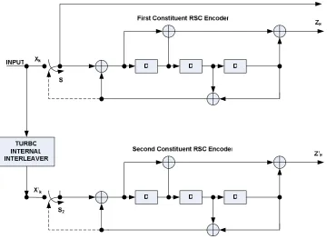
Turbo encoder is 1/3. The structure of the encoder is shown in Figure3.3 [36].
Figure 3.3: Structure of a Rate 1/3 UMTS Turbo Encoder
The two RSC encoders are identical, rate 1
3 encoders. The transfer function of the
8-state constituent code is given by Equation 3.1,
G(D) = [1,g1(D)
g0(D)] (3.1)
where,
3.4 Turbo Codes
Data is encoded by the first RSC encoder in the proper order and by the second
encoder after being interleaved. At first, the two switches S1 and S2 are in the up
position. The interleaver is a memory matrix depending on the size of the input word
size. Data can be interleaved in different ways. A simple block interleaver writes data to a memory block row-wise and reads it column-wise. Intra-row and
inter-row permutations can be performed on the data in the matrix in accordance with a
complex algorithm, which is fully specified in [5]. The parity bits thus generated after
encoding are transmitted along with the data bits, as three separate data streams.
The systematic input of the second encoder is completely redundant and need not be
transmitted, since the encoders are systematic and basically receive the same input.
The overall rate of the encoder is therefore 1/3. The number of data bits at the input
of the encoder isK. The first 3K bits of the encoder are in the form, X1,Z1, Z′
1, X2, Z2, Z′
2, .... , XK, ZK, ZK′ , where Xk is the k’th systematic data bit, Zk is the k’th
parity bit out of the upper (uninterleaved) encoder and Z′
k is the k’th parity bit out
of the lower (interleaved) encoder.
After the K input bits have been encoded, the trellis is forced into the all-zeros
state by the proper selection of tail bits. This is called trellis termination. Trellis termination is performed by obtaining the tail bits from the shift register feedback
after all the information bits have been encoded and re-transmitting them through
the encoder. Tail bits are thus padded after the encoding of information bits. The tail bits of a RSC encoder depend on the state of the encoder. It is necessary to calculate
each encoder’s tail bits separately and transmit them, since the states of the two
encoders would be different after the data bits have been encoded. The first three
tail bits are used to terminate the upper encoder and are generated by throwing the
upper switch S1 to the down position. The last three tail bits are used to terminate
the lower encoder (lower switch S2in down position) [36]. The transmitted bits for
the trellis termination would then be,
XK+1, ZK+1, XK+2, ZK+2, XK+3, ZK+3,XK′ +1,ZK′ +1,XK′ +2,ZK′ +2, XK′ +3,ZK′ +3.
where X represents the tail bits of the upper encoder, Z represents the parity bits
3.4 Turbo Codes
encoder and Z′ the parity bits corresponding to the lower encoder’s tail. The total
number of transmitted bits would then be (3K+12) and the code rate is K/(3K +
12).
3.4.1
Turbo Code Internal Interleaver
The interleaver is a logic block that receives a sequence of symbols from a fixed
alphabet at the input and reproduces the same symbols but with a different order
at the output. This reordering of the information bits can prevent burst errors. Typically, the output codewords of an RSC encoder have high Hamming Weights.
The Hamming weight of a codeword is the distance between the codeword and the
all-zero codeword. It is possible, however, for some input sequences to produce low weight codewords. Interleaving in combination with RSC encoding ensures that the
codewords produced by the Turbo codes have high Hamming weights. There has been
an intensive research on Turbo Code interleavers [17] [37] in the recent past.
The efficiency of an interleaver depends on its size, and the type of interleaving function used. Several different types of interleavers have been used in Turbo codes.
The most common type is the block interleaver, where data is read into a ROM row wise and read out column wise. The effectiveness of block interleavers reduces when
low weight sequences are confined to several consecutive rows, in which case the
inter-leaver may fail to spread certain sequences. The interleaving standard implemented
by the 3GPP group consists of the following steps. The data bits are first input to a rectangular matrix in a row wise fashion, with padding if necessary. Inter-row and
intra-row permutations are then performed on the data matrix and the data is output
column wise with pruning if necessary. The bits input to the Turbo interleaver are
denoted by X1, X2, X3, ... ,XK, where K is the integer number of bits and takes one
value within the range 40≤K ≤5114. The patterns for inter and intra row
permuta-tions are dictated by a complex algorithm specified in detail by the 3GPPP [5]. The
algorithm and the procedure for the 3GPP standard interleaving/de-interleaving is
3.5 Turbo Decoding
The Pseudo-Random interleaver using a primitive feedback polynomial [38] is
an-other popular interleaver used in communication systems. This class of interleavers
maps a bit in position i to some other location j, according to a randomly
(pseudo-randomly) generated address. Hardware wise, a PN sequence generator produces a sequence of addresses at which the data is stored in a RAM. An interleaver is
neces-sary at the encoder, while both the interleaver and a corresponding de-interleaver are
required at the decoder end. A more detailed hardware implementation is described in Chapter 4.
3.5
Turbo Decoding
Theoretical performance analysis of Turbo codes always assumes the usage of a Maximum Likelihood (ML) decoder at the receiver for efficient data recovery.
How-ever, the ML decoder is often too complex to be implemented for Turbo decoding
because of the very complex trellis structure caused by the interleavers between the two constituent RSC encoders. The output of each encoder depends on the last input
bit and the generator matrix, which enables the encoding process of a Turbo code to
be represented by two joint Markov processes. It is possible to decode Turbo codes by first independently estimating each process and then refining the estimates by
it-eratively sharing information between two decoders [35], since the two processes run
on the same input data. More specifically, the output of one decoder can be used
as the a priori information by the other decoder. It is necessary for each decoder
to produce soft-bit decisions in order to take advantage of this iterative decoding
scheme. Considerable performance gain can be achieved in this case, by executing
multiple iterations of decoding. The soft-bit decisions are usually in the form of Log
Likelihood Ratios (LLRs). The LLR data serves as the a priori information and is
defined as the likelihood of the received bit being a one rather than a zero as shown
3.5 Turbo Decoding
= 0 is made for a negative LLR.
Λi = ln
P(mi = 1|y)
P(mi = 0|y)
(3.2)
A decoder that accepts input in the form of a priori information and produces
output in the form of posteriori information is called aSoft Input Soft Output (SISO)
decoder. The inputs to the decoder are Systematic data, Parity data and thea priori
data from the previous decoder and the output of the decoder is the LLR data denoted
by Λi. The generic block diagram of a SISO decoder is shown in Figure3.4.
´ µ´ ¶ · ¸ ¹ ¶ · ¸ º »¼½¾¿À Á¾Âà ÄÅÆÇÈÀ Á¾ÂÇÅ
ÉÁȾ¼ ÄÅÆÇÈÀ Á¾ÂÇÅ
Ê˾ÈÂŽÂà ÌÍ ÎÈÂÇÈÂÏ ÄÅÆÇÈÀ Á¾ÂÇÅ
ÐÐÑ Ê½¾ÂÀ Á¾¿
Figure 3.4: Block Diagram of a SISO Decoder
3.5.1
Turbo Decoder Operation
Turbo decoding is an iterative application for the convolutional decoding
algo-rithm to successively generate an improved version of the received data. This section describes the essence of the Turbo decoding algorithm. For analysis, we consider a
bi-nary digital communication system over an Additive White Gaussian Noise (AWGN)
channel as shown in Figure 3.5.
Consider the UMTS Turbo encoder shown in Figure 3.1 for analysis. It is
3.5 Turbo Decoding
AWGN CHANNEL
TURBO ENCODER TURBO DECODER
AW GAUSSIAN NOISE
X Y r xˆ
SEQUENCE OF INFORMATION
BITS
SEQUENCE OF ENCODED BITS
RECEIVED SEQUENCE OF
BITS
ESTIMATE OF INFORMATION SEQUENCE
Figure 3.5: Channel Encoding and Decoding Model over an AWGN channel
modulation which is characterized by the following equation [35]:
y=a(2x−1) +n, (3.3)
where, a is the fading amplitude and n is the zero mean Additive White Gaussian
Noise with variance σ2 = N
0/2Es. The Log Likelihood of the SISO decoder using
this channel model can be expressed as the sum of three components:
Λi =
4a(is)Es
No
yi(s)+zi+li, (3.4)
where the term li is called the extrinsic information. While the first two terms of
the Equation 3.4 are the systematic channel observation (y(is)) and the information
derived from the other decoder’s output (zi), the extrinsic information represents the
new information derived from the current stage of decoding. It is important to pass
only the extrinsic information between the two decoders to prevent positive feedback
problems. The block diagram of an iterative decoder is shown in Figure 3.6.
As shown in Figure 3.6, the first decoder receives the first encoder’s scaled
par-ity and systematic bits as well as the a priori information derived from the second
decoder’s output. The extrinsic information for Decoder 1 is set to zero during the
first iteration, since the second decoder has not produced any information. During
this time, Decoder 1 produces the LLR data, from which the extrinsic information is
3.5 Turbo Decoding ÒÓÒÔÕÖ×ØÙÖÚÛ ÕÖÜÝÞßàáâßÖãÖÚ ÒÓÒÔÕÖ×ØÙÖÚä ÓåàÖÚßÖæçÖÚ ÕÖÜ ÓåàÖÚßÖæçÖÚ ÓåàÖÚßÖæçÖÚ ÕÖÜÓåàÖÚßÖæçÖÚ ÕÖ×áèáØå éßØ×ê Ò×æßÖÙ ëæÚáàìÕæàæ Ò×æßÖÙ ÒìèàÖíæàá× Õæàæ îáåæß ïèàáíæàÖ ïãàÚáåèá×ÓåðØÚíæàáØå ) 1 (
Λ Λ(2)
) 1 ( Z ) 2 ( r ) 0 ( r ) 1 ( r ) 1 ( Z ) 0 ( r ) 1 ( I ) 2 ( I mˆ
Figure 3.6: Block Diagram Schematic of an Iterative Turbo Decoder
as shown in Figure 3.6. The extrinsic information is then interleaved to provide the
a priori information for Decoder 2. The second decoder also receives the interleaved
systematic observation and the parity bits from the second encoder. Similar to
De-coder 1, the extrinsic information is derived from the LLR produced by DeDe-coder 2,
after which it is deinterleaved before serving as thea priori information for Decoder 1.
This iterative procedure continues until the LLR output of Decoder 2 does not change
significantly between successive iterations. The BER decreases from one iteration to the next, but eventually reaches a steady value according to the law of diminishing
returns [31]. After a particular number of iterations, the deinterleaved output of the
second decoder output provides a fairly accurate estimate of the transmitted symbols.
Several SISO decoding algorithms have been proposed in the literature. The Viterbi
Algorithm (VA) is an optimal method for minimizing the probability of symbol
er-ror. Although this algorithm is widely used in the decoding of convolutional codes,
the standard decoder for Turbo codes is the Maximum A Posteriori (commonly
re-ferred to as the MAP) algorithm. MAP is computationally intensive. Consequently, a
simplified version of MAP called Max-Log-MAP, which achieves a significant
complex-ity reduction with only a small performance degradation has been proposed in [9].
A modification to the Max-Log-MAP algorithm, the Log-MAP algorithm provides
nearly optimum performance while still maintaining the low complexity. Another