Temperature Distribution Analysis of
Composite Pin Fin By Experimental and
Finite Element Method
Y. Pratapa Reddy
*1, B. Jithendra Kumar
2, D. Srinivasulu
3, Dr.Ch. Srinivasa Rao
4PG Scholar, Department of Mechanical Engineering, Nova College of Engineering and Technology, Jangareddigudem, East Godavari (Dt) , A.P, India
HOD, Department of Mechanical Engineering, Nova College of Engineering and Technology, Jangareddigudem, East Godavari (Dt), A.P, India
Assoc. Professor, Department of Mechanical Engineering, Kallam Haranadhareddy Institute of Technology, Chowdavaram, Guntur, A.P, India.
Professor, Department of Mechanical Engineering, Kallam Haranadhareddy Institute of Technology, Chowdavaram, Guntur, A.P, India.
*1
Corresponding Author
ABSTRACT: Design of machine components plays a vital role in the field of Engineering where it includes the shape of component, size, applied loads, position and materials used. Due to the applied loads namely static, thermal and combined loads etc., the component undergoes stresses and deformations which effects the life of component and also the system.The Finite Element Method (F.E.M) is a numerical tool used for solving problems of engineering and mathematical problems in the fields of structural analysis, heat transfer, fluid flow, mass transport etc.,. For problems involving complicated geometries, loadings and material properties, it is generally not possible to obtain analytical solutions. These solutions generally require the ordinary or partial differential equations. Because of the complicated geometries, loadings and material properties, the solution can’t be obtained easily. So, in F.E.M the complicated shape of the component is splitted in to small entities called elements. Element characteristics are studied and then all the elements are combined to make a single system of component.
In the present work, Experiments have been conducted to find the temperature distribution within the pin fin made of composite metals and steady state heat transfer analysis has been carried using a finite element software ANSYS to test and validate results. The temperature distribution at different regions of pin fin are evaluated by FEM and compared with the results obtained by experimental work. The results are in good agreement and thus validated.
KEYWORDS: ANSYS, Composite material, Convection, Element Temperature, Heat Transfer Coefficient, Thermal Conductivity
I. INTRODUCTION
A composite is a material made by mixing of two different materials which provides a stronger material than the parent materials. The two materials are called, one is reinforcing material and the other is matrix material. In these materials the first one is mixed in the form of flakes, slices etc. and these are continuous. The practical example which is a concrete mixture used for building slabs.
resistance, thermal conductivity and corrosion resistance etc. The main drawback of composite materials is its manufacturing cost is more than that of conventional materials.
Heat transfer is defined as the energy transformation from one place to another due to temperature difference and flow from high temperature region to low temperature region without any applied external force. The modes of heat transfer are conduction, convection and radiation. A steady state is a condition where the temperature at each point of a body remains constant in a period of time. The basic condition of steady state heat conduction is given by
𝑑𝑇
𝑑𝑡 ≠ 0 𝑎𝑛𝑑 𝑑𝑇 𝑑𝑥 ≠ 0
Where T is temperature, t is time and x is the distance along the length of the material. The conduction heat transfer occurs by following the general equation of conduction as
𝑞 𝐴= −𝑘
𝑑𝑇 𝑑𝑥
The convection heat transfer happens by following the general equation as
𝑞 = ℎ𝐴(𝑇𝑤 − 𝑇𝑓)
Thermal conductivity is defined as the amount of energy conducted through the body of unit area and unit thickness in unit time. The thermal conductivities of different material is varies which depends upon its molecules structure , specific gravity, moisture content , temperature at base level etc.,. Heat transfer in composites materials plays an important role in the life span of composite materials. Due to temperature increase in the composite materials it affects the total materials that are combined in the composite. But due to uneven properties of different materials present in the composite material, they react in different manner in terms of thermal expansion which depends on thermal conductivity of materials.
Finite Element Method is a powerful numerical tool used to find out stress analysis and deformations occurred in beams,trusses, planes and in automotive machine components. If component is felt difficulty in analysing then it is considered as a small parts called elements. Then these element are joined with the help of nodes .By providing a serial numbers these all elements are joined to make a global system of component .Finally the boundary conditions are applied and we solve the equations and find out the unknown quantities. But these solutions give the approximate values but not exact solution. To solve the bigger matrices we depend on the software packages that solves the problems easily like as ANSYS.
1.1 Steps involved in Finite Element Analysis:
The various steps involved in Finite element analysis are in three stages .They are Pre-processing, Processing and Post- processing.
i) Pre-processing: It involves selection of element, providing element shape, thermal conductivity, density of material, nodes, and boundary conditions etc., which are treated as the initial information to solve the problem.
ii)Processing: In this the problem is solved using the above given shape, size and values of boundary conditions to the appropriate level of solution.
iii)Post processing: It provides the file output that is deformations, mode shapes, thermal distribution, etc., and list out the magnitudes of various processes.
II. LITERATURE REVIEW
Pradeep singh et al, [1] stated that the rectangular shaped extended surfaces shows the high rate of heat transfer when compared to other extensions at same length.
Kang Hiechan, [2] has made many experiments to find the fin efficiency and concluded that the efficiency of fin is useful when the value of NTU is zero otherwise the fin efficiency is high when the NTU is high and is used in air conditioning systems.
Shivdas S Kharche et al, [3] explained that the when a notch is provided on the surface of fin with a rectangular shape the fin supports for much heat transfer and compared the heat transfer rate of fins by changing the material from Aluminium to copper and found that copper shows much heat transfer value than aluminium.
Sandhya Mirapalli, et al, [4] had made a conclusion that for a triangular fin when the length is increased the heat flow percentage also increases at constant base temperature compared to rectangular fin.
Zhang, H.S et al., [6] resulted that a fabric heat sink temperature distribution is so nearer to common pin fin heat sink but the temperature decreases in axial direction by increasing the pin fin length. The temperature of the common pin fin heat sink is lower than the fabric pin fin heat sink at the root level (base),while the temperature increased at the length of pin fin because of the presence of base plate at the fin root level.
Sampath S S et al., [7] compared the temperature distribution of a cylindrical element at various points is carried out by providing the thermal conductivity and heat transfer coefficient and with prescribed boundary conditions and analysed with the help of simulation software and DOT NET software and the results are almost equal expect at the middle of the specimen it is just deviated..
Amol B. Dhumne et al., [8] resulted that to achieve high thermal performance the cylindrical perforated pin fins are used they leads to high heat transfer than the cylindrical pin fins. The efficiency varies depending upon clearance ratio and inter-spacing ratio and also lower clearance ratio, lower inter-fin spacing ratio and lower Reynolds numbers are suggested.
M. P. Shah et al., [9] compared the study of cylindrical pin fin was done by changing the material conductivity and heat transfer coefficient for copper ,AA1100,AA2011 materials and concluded that the heat transfer rate increases when thermal conductivity of material increases.
Y. Pratapa Reddy et al ., [10] had made an experimental analysis on a pin fins made of different materials (aluminum, copper) and composite bars (brass and aluminum , copper and aluminum) and concluded that the composite made of copper and aluminum shows higher efficiency than the solid pin fin and from these the values of base temperatures are considered as input source for simulation analysis on different materials.
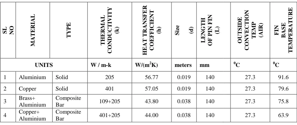
III. SPECIFICATIONS OF PIN FIN MATERIALS
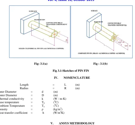
The various specifications of pin fins which are considered for analysis in this paper are tabulated in Table :3.1 and their sketches about their cross sectional details are shown in Fig 3.1 shows Aluminium pin fin, Fig 3.2 shows copper pin fin , Fig 3.3 shows composite pin fin (brass + Aluminium) , Fig 3.4 shows composite pin fin ( copper + Aluminium)
Table : 3.1 Parameters of Pin Fins
The sketches which describes the pin fin shapes used for simulation analysis and their cross section in terms of Isometric drawings are shown in below fig 3.1.(a) and fig 3.1 (b).
SL NO M AT E R IAL T YP E T H E R M A L CO NDUC T IVI T Y (k) H E AT T RAN SFER CO E F F ICI E N T
(h) Size (d)
L E NG T H O F P IN F IN (L ) O UT SI DE CO NVEC T IO N T E M P (AIR) F IN B AS E T E M P E RATU RE
UNITS W / m-k W/(m2K) meters mm 0C 0C
1 Aluminium Solid 205 56.77 0.019 140 27.3 91.6
2 Copper Solid 401 57.05 0.019 140 27.3 79.6
3 Brass+ Aluminium
Composite
Bar 109+205 43.80 0.038 140 27.3 75.8
4 Copper+ Aluminium
Composite
Fig: 3.1(a) Fig : 3.1(b)
Fig 3.1-Sketches of PIN FIN
IV. NOMENCLATURE
Length = L (m) Radius = R (m) Inner Diameter = d (m)
Outer Diameter = D (m) Thermal conductivity = k (W / m-K) Base temperature = Tb (0C)
Ambient Temperature = Ta ( 0
C) Density = ρ (kg/m3) Heat transfer coefficient = h (W/m2K)
V. ANSYS METHODOLOGY
In ANSYS methodology, the thermal analysis is selected in preferences .Next we select the proper element (8 node Solid 70) and in material properties isentropic analysis the material conductivity(k) (in W/m-K) is entered. In modelling stage the solid cylinder is made with provided radius (mm) and extruded to its normal direction to attain its length.
Meshing is considered as discritization of the specimen into elements of finite number and each element is solved and added to obtain results .The element shape is polygonal. In meshing stage a fine shape of 5 is selected and made the meshing for a solid cylinder and apply thermal loads in terms of temperature at base level of fin and convection heat transfer coefficient (h) value is provided on selected at outer surfaces or areas and Bulk temperature is provided as ambient temperature which it acts as medium for pin fin.
By selecting the steady state heat transfer analysis and solving the problem the results are obtained. In post processing, the plot results temperature distribution level is known through images and in list results the nodal temperatures are listed out.
5.1 ALUMINIUM SOLID CIRCULAR PIN FIN ANALYSIS:
Fig:5.1(a) Isometric view of solid Fig 5.1(b) Meshed view of Fig:5.1(c) Result of heat transfer pin fin made of Aluminium Aluminium of Aluminium pin fin
5.2 COPPER SOLID CIRCULAR PIN FIN IMAGES:
The temperature distribution analysis is done by changing the specimen material to copper, the following output images are obtained as shown in fig 5.2(a), (b) and (c).The temperature distribution is found to be 67.170C at the tip of the pin fin by providing the temperature at the base of the pin fin as 79.60C (experimental value-table 3.1).
Fig:5.2(a) Isometric view of solid Fig 5.2(b) Meshed view of Fig:5.2(c) Result of heat transfer pin fin made of copper copper pin fin of copper pin fin
5.3 COMPOSITE PIN FIN ANALYSIS (BRASS+ALUMINIUM):
Fig:5.3(a) Isometric view of solid Fig 5.3(b) Meshed view of Fig:5.3(c) Result of heat transfer pin fin made of brass+ aluminium brass+ aluminium of brass+ aluminium pin fin
5.4 COMPOSITE PIN FIN ANALYSIS (COPPER+ALUMINIUM):
In this stage consider the pin fin with the two materials as composite bar with copper and aluminium. In ANSYS the analysis is done by providing the base temperature as 63.9 0C(experimental value-table 3.1) and by gluing it through volumes it becomes a single solid system. It shows the temperature of 61.750C at its tip level. This is because of its high thermal and electrical conductivity of copper material. The output images are shown in fig 5.4(a), (b) and (c).
VI. RESULTS & DISCUSSIONS
6.1 SUMMERY OF RESULTS: The experimental results are compared with that of simulation analysis and are given in the following table.
Table 6.1(a) - RESULTS TABLE
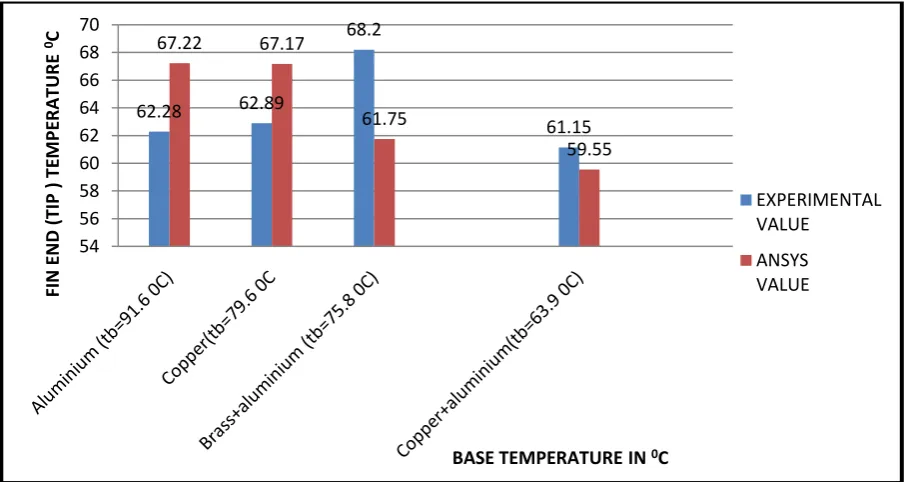
6.2 GRAPH: Comparison graph between ANSYS results and Experimental Values at the tip of the pin fin (Graph:1)
GRAPH-1
6.2 DISCUSSIONS: In this paper, an attempt is made to compare the fin tip temperatures obtained by experimental analysis and calculations made from the basics of Heat transfer to the values obtained from simulation software ANSYS. A constant cross section is considered for all materials.
62.28 62.89 68.2 61.15 67.22 67.17 61.75 59.55 54 56 58 60 62 64 66 68 70 FI N E N D (TIP ) TE M PE R A TU R E 0C
BASE TEMPERATURE IN 0C
EXPERIMENTAL VALUE ANSYS VALUE S . NO . M AT E R IAL T YP E Size (d) in m T H E R M A L CO NDUC T IVI T Y (k) in W/m -K T E M P E RATU RE O F F IN a t B ASE ( 0 C ) E XP E R IM E N T A L RE SU L T ( 0 C) ANSYS RE SU L T ( 0 C)
1 Aluminium Solid 0.019 205 91.6 62.28 67.22
2 Copper Solid 0.019 401 79.6 62.89 67.17
3 Brass+
Aluminium Composite Bar
0.019+
0.019 =0.038 109+205 75.8 68.20 61.75 4 Copper+
Aluminium Composite Bar
0.019+
In simulation analysis , a solid Aluminium and copper cylindrical pin fins shows much heat transfer at the end (tip) of the of pin fin than result obtained from experimental values.
In simulation analysis the Composite pin fins shows less rate of heat transfer at the end (tip) of the pin fin than solid cylindrical pin fins.
REFERENCES
1. Pardeep Singh., Harvinder lal., Baljit Singh Ubhi., “Design and Analysis for Heat Transfer through Fin with Extensions”,International Journal
of Innovative Research in Science, Engineering and Technology, ISSN 2319-8753,Vol. 3, Issue 5, pp 12054-12061,May 2014,.
2. Kang Hiechan, “Evaluation of Fin Efficiency and Heat Transfer Coefficient for Fined Tube Heat Exchanger", International Refrigeration and
Air Conditioning Conference. Paper -2539, pages 1-9, 2012
3. Shivdas S. Kharche., Hemant S. Farkade., “Heat Transfer Analysis through Fin Array by Using Natural Convection, ISSN 2250-2459, Volume
2, Issue 4, , pp 595-598. April 2012.
4. Sandhya Mirapalli., Kishore.P.S., “Heat Transfer Analysis on a Triangular Fin”, International Journal of Engineering Trends and Technology ,
ISSN: 2231-5381,Volume 19, Number 5, pp 279-284. Jan 2015.
5. I.Lakshmi Anusha., S.Murali., P.Srinivas Rao., P. Padmavathi., “CFD Analysis of Splayed Pin Fin Heat Sink using Advanced Composite
materials”, International Journal of Current Engineering and Technology, ISSN 2277 – 4106,Special Issue 2, pp 493-495,Feb 2014.
6. Zhang, H.S., Hu, J.Y., Yang, X.D. and Li, Y.L., “Evaluation on Heat Transferring Performance of Fabric Heat Sink by Finite Element
Modeling”., Journal of Textile Science and Technology, 1,pp 25-32, 2015.
7. Sampath S S., Anil Antony Sequeira,.,Chithirai Pon Selvan M., Sawan Shetty, “Comparative Thermal Analysis of Bar Element Connected to
Different Heating Sources”,International Journal of Emerging Technology and Advanced Engineering, ISSN:2250-2459,Volume 4, Issue 12, pp :72-78,December 2014.
8. Amol B. Dhumne., Hemant S. Farkade., “Heat Transfer Analysis of Cylindrical Perforated Fins in Staggered Arrangement”, International
Journal of Innovative Technology and Exploring Engineering (IJITEE), ISSN: 2278-3075, Volume-2, Issue-5, April 2013.
9. M. P. Shah., K. S. Mehra., S.Gautam., P.Negi., “Transient and Steady State Analysis of Fin Using FEM for Different Material”,International
Journal for Research in Applied Science and Engineering Technology, Vol. 2, Issue VI, pp 36-40, June 2014.
10. Y.Pratapa Reddy., B.Jithendra Kumar., G.Raju., Dr.Ch.Srinivasa Rao., “Fabrication and Thermal Analysis of Composite Pin-Fin”, International