Allworx Installation Instructions
16
0
0
Full text
(2) Installation Instructions. Packaging Components Quantity. Item. Part Number. 1. Shipping Container. 4410100. 2. Foam End Caps. 4430100. 1. Protective Plastic Bag. 4420100. Parts List Quantity. 1. Item. Part Number. Allworx 10x Server –Single Drive. 7000100. Allworx 10x Server - Mirrored disk drive. 7000200. 1. Power Cord. 3000100. 1. Line-in Audio Adapter Cable. 3000300. 1. Documentation Kit. 6000120. 1. Table Mount Hardware Kit. 6000110. 1. Rack and Wall Mount Hardware Kit. 6000100. 1. Client/Server Software Kit. 6000140. Information in this document is subject to change without notice. 2002 InSciTek Microsystems, Inc. Reproduction in any manner whatsoever without the written permission of InSciTek Microsystems, Inc. is strictly forbidden. Trademarks and trade names may be used in this document to refer to either the entities claiming the marks and names or their products. InSciTek Microsystems, Inc. disclaims any proprietary interest in trademarks and trade names other than its own. March 2003. 032103 2. Doc. No. 5000100.
(3) Installation Instructions Table of Contents 1. Safety Instructions. 5. 2. Allworx Server Installation. 5. 3. Data Network Installation. 8. 4. Accessories Installation. 9. 5. Regulatory Notices. 13. List of Figures Figure 1 – Rack Mount Bracket Installation. 6. Figure 2 – Wall Mount Bracket Installation. 6. Figure 3 – Earth Connection and Voltage Selection. 6. Figure 4 – Example Allworx Office Configuration. 10. Figure 5 - Allworx Server Rear and Front Panel Views. 11. 3.
(4) Installation Instructions. 4.
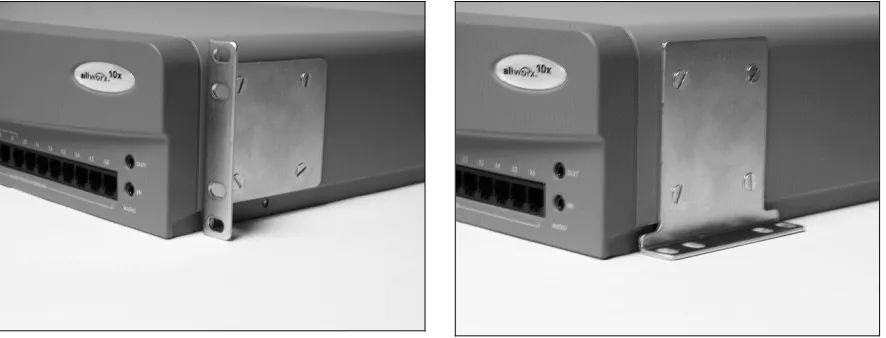
(5) Installation Instructions 1. Safety Instructions To avoid damaging the Allworx server or associated system components, be sure the voltage switch on the rear of the unit is set to the appropriate setting for your location. The unit is shipped in the United States with the switch set to 115 VAC. Before working inside the Allworx server, unplug the unit to help prevent electrical shock or system damage. To help prevent electrical shock, the separate protective earthing terminal located next to the power receptacle on the rear panel must be permanently connected to earth using 18 AWG wire or larger. The power cable is also equipped with a three-pronged plug to help ensure proper grounding. Do not use adapter plugs or remove the grounding prong from the cable. If an extension cord is required, use a threewire cable with properly grounded plugs. To reduce the risk of fire, use only 26 AWG or larger UL listed or CSA certified telecommunications line cord. To help protect the Allworx system from sudden, transient increases and decreases in voltage, use a surge suppressor, line conditioner, or uninterruptible power supply (UPS). Be sure nothing rests on or interferes with the system’s power cables and that the cables are not located where they can be stepped on or tripped over. Do not spill food or liquids on the Allworx server. If the server gets wet refer to Preventive Maintenance cleaning instructions in Chapter 4. Do not push any objects into the openings of the server. Doing so can damage the unit or cause electrical shock. Keep the Allworx server away from heat sources such as radiators. Do not block the cooling fan opening on the rear panel.. 2. Allworx Server Installation Remove all parts from the shipping container. NOTE: Save all shipping and packaging materials. Verify all items against the parts list. If any items are missing, contact your distributor or InSciTek Microsystems customer support 585-421-3850.. Table Top or Shelf Placement Install the four rubber feet on the bottom of the Allworx server. Remove the paper backing from each rubber foot. Place one foot on the circle at each corner on the bottom of the chassis. Rack Mount Installation Place the brackets so that the smaller faces extend away from the front of the unit to accommodate installation into the rack (Figure 1). Install the mounting brackets on each side of the server chassis using the four 8-32 flat head screws. Proceed to the Power Connection instructions below and perform the steps appropriate for your installation before placing the system into the rack. Install the server into the rack using appropriate hardware.. 5.
(6) Installation Instructions Wall Mount Installation NOTES: Be sure there is enough clearance between the server’s front and rear panels and any walls or other equipment to allow power, network and telephony connections. Place the brackets so that the smaller faces are facing the bottom of the unit (Figure 2). Install the mounting brackets on each side of the server chassis using the four 8-32 flat head screws. Secure the unit to the wall using appropriate hardware. WARNING: The Allworx server must be securely mounted to the wall to avoid equipment damage or personal injury. Be sure to use suitable mounting hardware and anchors for the wall material. A minimum hardware size of #8 is highly recommended.. Figure 1 – Rack Mount Bracket Installation. Figure 2 – Wall Mount Bracket Installation. Power Connection WARNING: Failure to follow the steps below may result in equipment damage, personal injury, and void the product warranty. Connect the unit to earth using the protective earthing screw located next to the power receptacle on the rear panel.. Voltage setting switch. Protective earthing screw. Figure 3 – Earth Connection and Voltage Selection Be sure the voltage switch on the rear of the unit is set to the appropriate setting for your location. The unit is shipped in the United States with the switch set to 115 VAC. Insert the female end of the power cord into the receptacle on the rear of the unit. Connect the other end to the power source. The Allworx server will automatically begin to power up.. 6.
(7) Installation Instructions As the Allworx server progress through the power up sequence, the front panel lights will respond as follows (Figure 5): Power. Lights steady green when the unit is ready.. Drive. Flickers as the power up sequence progresses.. Alert. Lights orange momentarily when the unit initially powers on, then turns off immediately.. Telephony Connections Connect the RJ-11 cables from your telephone service provider’s central office to the Outside Lines ports on the front panel starting with port number 1. CAUTION: To reduce the risk of fire, use only 26 AWG or larger UL listed or CSA certified telecommunications line cord. NOTES: A maximum of 9 central office lines can be connected to the Allworx server using the standard loop-start or optional ground-start service. If you expect to have central office lines directly connected to specific internal extensions, begin making the central office connections at port 16 and work towards port 4 to maintain the option of using ports4-9 as either internal extensions or central office lines. Connect an analog telephone device to the Power Fail port on the front panel. NOTE: This connection provides telephone service in the event the Allworx server loses power or fails. Analog Telephone Extensions Connect the RJ-11 cables from each analog telephone to the Inside Phone Extensions ports on the front panel using the first available port beginning with port 4. SIP Telephone Extensions Connect the RJ-45 cables for each IP telephone to the Office Network ports on the front panel. NOTE: Although the Office Network ports are labeled 1-4, connections can made be to any available port in any order. If you have more IP telephones than can be accommodated by the available ports, you will need to use a switch or hub to concentrate the connections to the server. Figure 4 shows an example of an Allworx office network configuration.. 7.
(8) Installation Instructions 3. Data Network Installation Before connecting the data network to the Allworx server, some pre-planning is required. Consider the following network configuration guidelines: DHCP Server. The Allworx server includes a LAN-side DHCP server that is enabled by default. If the Allworx server is being connected to another local area network, one of the DHCP servers needs to disabled. If IP telephones are being installed, refer to the Allworx System Administrator’s Guide for more complete information on IP telephone and DHCP server configuration.. Firewall Configuration. The Allworx server includes an enterprise class firewall. If the Allworx WAN is being connected directly to the Internet, be sure to select one of the NAT firewall options before making the physical connection. Refer to the System Administrator’s Guide for this and other firewall configuration options.. Domain Name Server. If a local domain name server is available on a LAN, use that IP address when configuring the Allworx server. Otherwise, contact your Internet Service Provider for the proper IP address. If the Allworx server will be used as a public host:. Mail Server. •. Be sure there is a direct connection from the Allworx WAN to the Internet.. •. Be sure to update your domain name registrar name server record with the Allworx public server address.. •. Be sure your Internet Service Provider assigns a static IP address. Do not use dynamic addressing.. You must decide whether inbound email will be routed through the Allworx server. If the Allworx server is to be the primary inbound mail server, be sure there is a connection from the Allworx WAN to the Internet. If using an external mail server to support the Allworx All-in-One™ unified messaging, you must add an account to the email client to download POP3 email from the Allworx server (Refer to the Allworx System Administrator’s Guide). For outbound mail, the Allworx server can be the SMTP server if it is on a LAN and the WAN is connected to the Internet.. Internet Web Server. Be sure to connect the Allworx WAN to the Internet. Additional guidelines for web server configuration can be found in the Allworx System Administrator’s Guide.. NOTE: Cross-over cables are not required in the following sections. The Allworx Office Network ports provide automatic cross-over. Figure 4 shows an example of an Allworx network configuration.. Local Area Network (LAN) Connection Connect the RJ-45 cables for the PC network to the Office Network ports on the front panel (Figure 5). The green LED will come on indicating end-to-end connectivity, and flicker indicating transmission activity. The amber LED indicates port speed: On = 100MB/S, Off = 10MB/S. NOTE: Although the Office Network ports are labeled 1-4, connections can made be to any available port in any order.. 8.
(9) Installation Instructions Wide Area Network (WAN) Broadband Connection Connect a cable from your broadband service modem to the WAN port on the front panel (Figure 5). The green LED will come on indicating end-to-end connectivity, and flicker indicating transmission activity. The amber LED indicates port speed: On = 100MB/S, Off = 10MB/S. NOTE: The WAN port may also be used to connect one Allworx server to another through a LAN.. 4. Accessories Installation. Adding a Fax Machine Connect the RJ-11 cable from your fax machine to the first available analog port on the front panel. Refer to the System Administrators Guide to complete the setup and configuration. Music and Paging Music-on-Hold Connect the output from your music system to the Allworx server using the Line-in Audio Adapter Cable provided with your Allworx system. Insert the male cable end into the audio connector labeled “In” on the front panel (Figure 5). Paging Connect the Allworx server to the input of your paging system using the audio connector labeled “Out” on the Allworx front panel (Figure 5).. The Allworx server is now ready for user set up. Proceed to the Allworx System Administrator’s Guide.. 9.
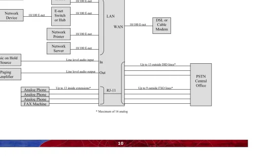
(10) Installation Instructions Figure 4 – Example Allworx Office Configuration. “Unlimited” number of SIP. SIP Phone SIP Phone SIP Phone. Network Device. 10/100 E-net 10/100 E-net 10/100 E-net. 10/100 E-net. E-net Switch or Hub E-net Switch or Hub. Allworx Server 10/100 E-net. 10/100 E-net. LAN WAN. Music on Hold Source. Network Printer. 10/100 E-net. Network Server. 10/100 E-net. Line level audio input. Line level audio output. Paging Amplifier Analog Phone Analog Phone Analog Phone FAX Machine. Up to 13 inside extensions*. In. 10/100 E-net. DSL or Cable Modem. Up to 13 outside DID lines*. Out. Up to 9 outside FXO lines*. RJ-11. * Maximum of 16 analog. 10. PSTN Central Office.
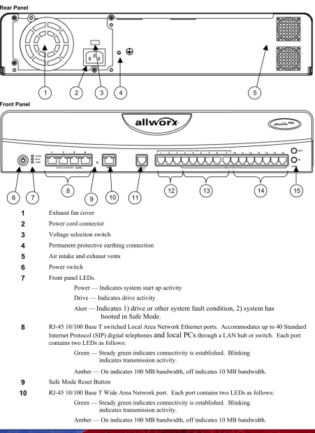
(11) Installation Instructions Figure 5 - Allworx Server Rear and Front Panel Views Rear Panel. 1. 2. 3. 4. 5. Front Panel. 6. 7. 8. 10. 9. 12. 11. 1. Exhaust fan cover. 2. Power cord connector. 3. Voltage selection switch. 4. Permanent protective earthing connection. 5. Air intake and exhaust vents. 6. Power switch. 7. Front panel LEDs.. 13. 14. 15. Power — Indicates system start up activity Drive — Indicates drive activity Alert — Indicates 1) drive or other system fault condition, 2) system has. booted in Safe Mode. 8. RJ-45 10/100 Base T switched Local Area Network Ethernet ports. Accommodates up to 40 Standard Internet Protocol (SIP) digital telephones and local PCs through a LAN hub or switch. Each port contains two LEDs as follows: Green — Steady green indicates connectivity is established. Blinking indicates transmission activity. Amber — On indicates 100 MB bandwidth, off indicates 10 MB bandwidth.. 9 10. Safe Mode Reset Button RJ-45 10/100 Base T Wide Area Network port. Each port contains two LEDs as follows: Green — Steady green indicates connectivity is established. Blinking indicates transmission activity. Amber — On indicates 100 MB bandwidth, off indicates 10 MB bandwidth.. 11.
(12) Installation Instructions 11. RJ-11 Power Fail analog phone connector that connects to FXO RJ-11 port #1 during power failure. 12. RJ-11 dedicated loop-start FXO ports for central office connection (Ports 1-3). 13. RJ-11 loop-start FXO for central office connection or FXS universal telephone auto-sensing ports for analog extension connection (Ports 4-9). 14. RJ-11 FXS ports for analog or fax extension (Ports 10-16). 15. 3.5 mm audio mini jacks for music-on-hold and overhead paging. 12.
(13) Installation Instructions 5. Regulatory Notices. FCC Part 68 This equipment complies with Part 68 of FCC rules and the requirements adopted by ACTA. On the, back side of this equipment is a label that contains, among other information, a product identifier in the format US: AAAEQ##TXXXX. If requested, provide this number must be provided to the telephone company. A plug and jack used to connect this equipment to the premises wiring and telephone network must comply with the applicable FCC Part 68 rules and requirements adopted by the ACTA. A compliant telephone cord and modular plug is provided with this product. It is designed to be connected to a compatible modular jack that is also compliant. See installation instructions for details. The REN is used to determine the number of devices that may be connected to a telephone line. Excessive RENs on a telephone line may result in the devices not ringing in response to an incoming call. In most but not all areas, the sum of RENs should not exceed five (5.0). To be certain of the number of devices that may be connected to a line, as determined by the total RENs, contact the local telephone company. For products approved after July 23, 2001, the REN for this product is part of the product identifier that has the format US:AAAEQ##TXXXX. The digits represented by ## are the REN without a decimal point (e.g., 03 is a REN of 0.3). For earlier products, the REN is separately shown on the label. If this equipment causes harm to the telephone network, the telephone company will notify you in advance that temporary discontinuance of service may be required. But if advance notice isn't practical, the telephone company will notify the customer as soon as possible. Also, you will be advised of your right to file a complaint with the FCC if you believe it is necessary. The telephone company may make changes in its facilities, equipment, operations or procedures that could affect the operation of the equipment. If this happens the telephone company will provide advance notice in order for you to make necessary modifications to maintain uninterrupted service. If trouble is experienced with this equipment, for repair or warranty information, please contact our company. If the equipment is causing harm to the telephone network, the telephone company may request that you disconnect the equipment until the problem is resolved. Connection to party line service is subject to state tariffs. Contact the state public utility commission, public service commission or corporation commission for information. Industry Canada NOTICE: This equipment meets the applicable Industry Canada Terminal Equipment Technical Specifications. This is confirmed by the registration number. The abbreviation, IC, before the registration number signifies that registration was performed based on a Declaration of Conformity indicating that Industry Canada technical specifications were met. It does not imply that Industry Canada Approved the equipment. NOTICE: The Ringer Equivalence Number (REN) for this terminal equipment is 0.1. The REN assigned to each terminal device provides an indication of the maximum number of terminals allowed to be connected to a telephone interface. The termination on an interface may consist of any combination of devices subject only to the requirement that the sum of the Ringer Equivalence Numbers of all the devices does not exceed 5.. 13.
(14) Installation Instructions RADIO AND TELEVISION INTERFERENCE This equipment has been tested and found to comply with the limits for a Class B digital device, pursuant to Part 15 of the FCC rules. These limits are designed to provide reasonable protection against harmful interference in a residential installation. This equipment generates, uses and can radiate radio frequency energy and, if not installed and used in accordance with the instructions, may cause harmful interference to radio communications. However, there is no guarantee that interference will not occur in a particular installation. If this equipment does cause harmful interference to radio or television reception, which can be determined by turning the equipment off and on, the user is encouraged to try to correct the interference by one or more of the following measures: - Reorient or relocate the receiving antenna. - Increase the separation between the equipment and the receiver. - Connect the equipment into an outlet on a circuit different from that to which the receiver is connected. - Consult the dealer or an experienced radio/TV technician for help. You may also find helpful the following booklet, prepared by the FCC: "How to Identify and Resolve Radio-TV Interference Problems." This booklet is available from the U.S. Government Printing Office, Washington D.C. 20402. Changes and Modifications not expressly approved by the manufacturer or registrant of this equipment can void your authority to operate this equipment under Federal Communications Commissions rules.. 14.
(15) Installation Instructions. 15.
(16) Installation Instructions. 16.
(17)
Figure
Related documents