AT&T
Issue 1, June 1988
AT&T SYSTEM 25
INSTALLATION AND
Printed in USA
TO ORDER COPIES OF THIS DOCUMENT REFER TO DOCUMENT NUMBER 555-530-103
Contact: Your AT&T sales representative, or
Call: 800-432-6600, Monday through Friday between 7:30 am and 6:00 pm EST, or
In Canada call: 800-255-1242
Write: AT&T Customer Information Center 2855 North Franklin Road
P.O. Box 19901
Indianapolis, Indiana 42619
Every effort was made to ensure that complete and accurate at the time of subject to change. This document will changes.
the information in this document was printing. However, this information is be reissued periodically to incorporate
AT&T SYSTEM 25
This telephone equipment is registered with the Federal Communications Commission (FCC) in accordance with Part 68 of its Rules. In compliance with the Rules, be advised of the following:
MEANS OF CONNECTION
C o n n e c t i o n o f this telephone e q u i p m e n t t o the nationwide telecommunications network shall be through a standard network interface USOC RJ21X jack. Connection to private line network channels requires USOC RJ2GX jack for tie lines or USOC RJ21X jack for off-premises station lines. These can be ordered from your telephone company.
NOTIFICATION TO THE TELEPHONE COMPANY
If the system is to be connected to off-premises stations (OPSs), you must notify the telephone company of the OPS class of service, OL13C, and the service order code, 9.0F.
Upon the request of the telephone company, inform them of the following:
—
—
—
The Public Switched Network “lines” and the Private “lines” to which you will connect the telephone equipment.
The telephone equipment’s “registration number” and “ringer equivalence number” (REN) from the label on the equipment.
For private line connections, provide the facility interface TL31M for tie lines. You must also specify the service order 9.0F.
— For each jack, provide the sequence in which lines are to be
connected; the type lines and the facility interface code and the
ringer equivalence number by position, when applicable.
This telephone equipment should not be used on coin telephone lines.
Connection to party line service is subject to state tariffs.
REPAIR INSTRUCTIONS
If you experience trouble with this telephone equipment, contact the AT&T Business Customer Service Center on 1-800-242-2121. The telephone company may ask that you disconnect this equipment from the network until the problem has been corrected or until you are sure that this equipment is not malfunctioning.
System 25 troubles that must be escalated to a higher level of maintenance should be referred to the National Service Assistance Center on 1-800-628-2888.
RIGHTS OF THE TELEPHONE COMPANY
If your telephone equipment causes harm to the telephone network, the telephone company may discontinue your service temporarily. If possible, they will notify you in advance. But if
be notified as soon as possible. You complaint with the FCC.
Your telephone company may make operations, or procedures that could equipment. If they do, you will be
advance notice isn’t practical, you will will be informed of your right to file a
changes in its facilities, equipment, affect the proper functioning of your notified in advance to give you an opportunity to maintain uninterrupted telephone service.
interference.
Registration Number Ringer Equivalence Network Interface
AS593M-71565-MF-E 0.5A
RJ21X or RJ2GX
PRIVATE LINE SERVICE
Service Order Code 9.OF
Facility Interface Code
●Tie Lines TL31M
● Off-Premises Stations OL13C
FCC WARNING STATEMENT
●
●
●
Federal Communications Commission (FCC) Rules require that you be notified of the following:
This equipment generates, uses, and can radiate radio frequency energy and, if not installed and used in accordance with the instruction manual, may cause interference to radio communications.
It has been tested and found to comply with the limits for a Class A computing device pursuant to Subpart J of Part 15 of FCC Rules, which are designed to provide reasonable protection against such interference when operated in a commercial environment.
Do not open the fan assembly or remove rear cabinet cover before
unplugging the cabinet from the electrical outlet. Wait at least five
minutes after unplugging the power cord before removing the rear
cover or power supply. The AT&T System 25 cabinets are not user
serviceable. Some voltages inside the cabinets are hazardous.
This equipment is to be serviced only by qualified technicians.
CUSTOMER WARNING
INTRODUCTION
FCC PRECAUTIONS
INSTALLATION
TOOLS AND TEST EQUIPMENT
CROSS-CONNECT EQUIPMENT DESCRIPTION
Trunk Access Equipment
700A-110-B1-25 or 700A-66-B1-25 (157BF) Cut-Down
J a c k
10B Emergency Transfer Unit (ETU)
Station Interconnect Panel (SIP)
617A Panel
Adapters
Fanning Strip
Cables
Splitter Cables
Octopus Cables
Cable Labels
Symbols Used in Figures
PREINSTALLATION REQUIREMENTS
Table and Backboard
Network Interface
AC Power
Grounding
Lightning Protection
Building Wiring
INSTALL SYSTEM CABINETS
Position Cabinet(s)
Check Cabinet Contents
Required Circuit Pack Positions
Label Connectors on Back Cover
Install 4A Retainer Clips
Connect Cabinets
TDM Bus Connections
Connect Administration Equipment
Cold Start the System
Check Performance of Cabinet Components
Report Problems
Initialize System
INSTALL CROSS-CONNECT EQUIPMENT
Install TAE, 617A
Panels, and Fanning Strips
Mount 858A or Z210A1 Adapters
INSTALL MODULAR BULK POWER SUPPLY (Optional)
INSTALL EQUIPMENT ROOM TRUNK CABLING
Connect Network Interfaces to TAE Blocks
Connect Cabinets to TAE Blocks
Connect Ground Start, Loop Start, and DID Trunks
Connect Tie Trunks
Connect Coupled Bonding Conductor (CBC)
INSTALL EQUIPMENT ROOM STATION CABLING
Connect Building Wiring to SIP
Modular Plug Termination
4-Pair Cable Terminations
Connect Cabinets to SIP
Prepare Carrier Loading Labels
Modify Octopus Cables if Required
Make SIP Connection for CPU/Memory
Make SIP Connections to Cabinet for 7300H Series
Terminals
Make SIP Connections to Cabinet for MET Sets
Make SIP Connections to Cabinet for Single-Line Sets
Make SIP Connections for Data Terminals and
Computers
Perform SIP Housekeeping
INSTALL EMERGENCY TRANSFER UNITS (ETUs)
Make Emergency Transfer Connections
Install Ground-Start Key
INSTALL ATTENDANT CONSOLE
Single-Line and 73001-1 Series Voice Terminals With
Associated ADUs
Off-Premises Stations
Out-Of-Building Voice Terminals
Out-Of-Building Wiring
Stand-Alone Data Terminals
ADU Connections
MADU Connections
INSTALL CUSTOMER’S SAT
Nonswitched Connection of Equipment Plugged Into
System AC Outlet
Nonswitched Connection of Equipment
On-Premises Digital Switched Connection
Off-Premises Nonswitched Connection
Off-Premises Switched Connection
INSTALL CUSTOMER’S DTU
INSTALL Station Message Digital Recording (SMDR)
Equipment
INSTALL STARLAN NETWORK INTERFACE
Shared System 25 Voice/STARLAN NETWORK Data
Connections
Single-Line Voice Terminals
7300H Series Voice Terminals
INSTALL MUSIC-ON-HOLD INTERFACE
FCC-Registered Music Source Interface
Non-FCC Registered Music Source Interface
INSTALL EXTERNAL ALERTS
INSTALL RECORDED DELAY ANNOUNCEMENT
INSTALL DICTATION SYSTEM INTERFACE
INSTALL PAGING SYSTEM INTERFACE
Direct Connection to TN763 Auxiliary Trunk CP
Connection to TN763 Auxiliary Trunk CP (278A
TEST
TEST
TEST
TEST
TEST
TEST
TEST
OUTGOING TRUNKS
INCOMING DID TRUNKS
INCOMING TIE TRUNKS
7300H SERIES VOICE TERMINALS
SINGLE-LINE VOICE TERMINALS
DIAL ACCESS CODES
SYSTEM FEATURES
ARS and SMDR Tests
DGC Test
System Speed Dialing Test
PDC Login Test
Call Coverage Test
TEST ATTENDANT CONSOLE
TEST SELECTOR CONSOLE
TEST DATA TERMINAL DIALING FEATURE
MAKE POOLED MODEM TEST CALL
TEST
TEST
TEST
TEST
TEST
TEST
TRANSFER TO DATA
EXTERNAL ALERT (NIGHT SERVICE)
DICTATION SYSTEM ACCESS
PAGING INTERFACE
MUSIC-ON-HOLD
EMERGENCY TRANSFER
Test Touch-Tone Receivers
Attendant Console LED
Power Supply LED
Switches and Test Points
System Administration Terminal
Remote Initialization and Maintenance (RIM)
MAINTENANCE STRATEGY
Total System Failures
Port Problems
Common Control Problems
Station, Wiring, and Trunk Problems
Automatic Maintenance Tests
Maintenance Failure
USING THE DIGITAL TAPE UNIT
Setting Up the DTU
Saving Translations
Verifying Translations
Restoring Translations
ROUTINE MAINTENANCE
Reseating and Replacing Circuit
Removing and Restoring Power
Restarting the System
ERROR LOG
Packs
Accessing the Error Log From the SAT
ERROR MESSAGES
Clearing System-Detected Troubles
Complete System Failure
Common Control Trouble
Circuit Pack Trouble
Service
Frontplane Ribbon Connector Trouble (Release 1
Only)
Power Supply Trouble
Power Supply Protection
Power Supply Replacement
Fan Assembly Trouble
Overheating Trouble
Backplane and Cabinet Trouble
CLEARING USER-DETECTED TROUBLES
Administration Equipment Troubles
Time-Keeping Troubles
Voice Terminal and Wiring Troubles
Voice Transmission Troubles
7300H Series Terminal Troubles
Virtual Facilities Troubles
Trunk Troubles
Outgoing Trunk Problems
Incoming Trunk Problems
Error Log Interpretation: Loop-Start Trunks
Error Log Interpretation: Ground-Start Trunks
DID Trunks Troubles
Switched Loop Attendant Console Troubles
Special Port Circuit Options for Stations and Trunks
Data Line Troubles
Multiple Troubles or Trouble That Cannot Be
Diagnosed
4-82
4-82
4-83
4-83
4-84
4-85
4-86
4-90
4-90
4-91
4-91
4-92
4-93
4-94
4-100
4-101
4-103
REFERENCES
5-1
ABBREVIATIONS AND ACRONYMS
6-1
APPENDIX A: SYSTEM WIRING TABLES
Connector Pin Assignments
System 25 Building Wiring
A-1
A-1
A-1
APPENDIX B:
APPENDIX C:
Parts Listing
System Additions or Changes
B-1
C-1
Evaluate Cabinet Unit Power Load
Add Circuit Pack
Add
Add
Terminal
Trunk
Terminal
Add Pooled Modem
Replace Voice-Only Terminal With Voice/Data
Circuit Pack
Add Auxiliary Equipment
APPENDIX D:
APPENDIX E:
System Upgrades
Administration Codes and Data
Default Dial Code Assignments
APPENDIX F:
GLOSSARY
INDEX
Administration Error Messages
C-10
C-11
C-12
C-13
C-13
D-1
E-1
E-1
F-1
G-1
Figure 2-1.
Figure 2-2.
Figure 2-3.
Figure 2-4.
Figure 2-5.
Figure 2-6.
Figure 2-7.
Figure 2-8.
Figure 2-9.
Figure 2-10.
Figure 2-11.
Figure 2-12.
Figure 2-13.
Figure 2-14.
Figure 2-15.
Figure 2-16.
Figure 2-17.
Figure 2-18.
Figure 2-19.
Figure 2-20.
Figure 2-21.
Figure 2-22.
Figure 2-23.
Figure 2-24.
Figure 2-25.
Figure 2-26.
Figure 2-27.
Figure 2-28.
Figure 2-29.
Figure 2-30.
Figure 2-31.
Figure 2-32.
Figure 2-33.
Figure 2-34.
10B ETU
617A Panel
SIP Adapters
50A Fanning Strip
Splitter Cables
Octopus Cable
Cable Labels
Typical System 25 Floor Plan
AC Power Distribution—Multiple Cabinet System
Three-Cabinet System, Front View With Covers
Removed
Position of Shorting Plugs on CPU/Memory
Circuit Pack
4A Retainer Clip Installation
TDM Bus Terminations (Rear View of 3-Cabinet
System)
Temporary SAT and DTU Connections
Typical System 25 Port Circuit Pack*
SIP and TAE Backboard Layout
Alternate SIP and TAE Backboard Layout
Mounting Adapters
Voice and Data Station Records Form (Example
Entered)
Modular Plug Terminations Connected to the SIP
Cut Down Terminations Connected to the SIP
Carrier Loading Label
Standard and Modified Octopus Cables
Mounting Octopus Cable on Fanning Strip
10B Emergency Transfer Unit
Emergency Transfer Unit Connections
Ground Start Key Installation
Attendant Console With DXS Console
Remotely Powered DXS Console Connection
Stand-Alone Voice Terminal Connections
Stand-Alone Remotely Powered Voice Terminal
Connections
Single-Line Terminal/ADU Connections
7300H Series Terminal/ADU Connections
Local Powering of an ADU
2-94
Nonswitched Connection of Peripheral
Equipment
On-Premises Peripheral Equipment With
Switched Connection to CPU/Memory
Off-Premises Peripheral Equipment With Direct
Connection to CPU/Memory
ZTN84 STARLAN Interface CP Connection
Single-Line Analog Terminal/STARLAN
NETWORK Workstation Connections
7300H Series Terminal/STARLAN NETWORK
Workstation Connections
Music Source, FCC Registered
Music Source, Non-FCC Registered
External Alerts
Paging System Connection to TN763 Circuit
Pack . . . .
Paging System Connection to TN763 Circuit
Pack (278A Adapter Required)
Response to System 25 Trouble Report
Clearing Power Supply Troubles (Sheet 1 of 2)
Clearing CO Trunk Troubles
Clearing 4-Wire Tie Trunk Troubles (Sheet 1 of 4)
Clearing STARLAN Interface Troubles
Clearing Tie Trunk Troubles (Sheet 1 of 5)
Clearing Paging Equipment Troubles
AC Power Schematic
System Cabinet Backplane (Sheet 1 of 2)
TDM Signal Designations on Cabinet Backplane
Power Designations on Cabinet Backplane
Clearing Virtual Facilities Troubles (Sheet 1 of 3)
Clearing Switched Loop Attendant Console
Troubles (Sheet 1 of 5)
Typical System 25 Port Circuit Pack
Table 2-A.
Table 2-B.
Table 2-C.
Table 2-D.
Table 2-E.
Table 2-F.
Table 2-G.
Table 4-A.
Table 4-B.
Table 4-C.
Table 4-D.
Table 4-E.
Table 4-F.
Table A-A.
Table A-B.
Table C-A.
Table C-B.
Table E-A.
Table E-B.
Table E-C.
Table E-D.
Table E-E.
Table E-F.
Table E-G.
Table E-H.
Table E-I.
Table E-J.
Table E-K.
Table E-L.
Table E-M.
Tools and Test Equipment Required for
Installation
Circuit Packs and Their Functions
Displayed SAT Messages During Cold or Warm
Restart
Circuit Pack LED Status Indications
Trunk Circuit Packs
Circuit Pack Versus Terminal Type
Feature Button Abbreviations and Labels
Displayed SAT Messages During Cold or Warm
Start
Power Supply Test Points
Circuit Pack Voltages—Symptoms (See Note)
25-Pair Connector to Backplane Designations
Station/Trunk/Special Port Circuit Pack Options
Applicable Actions for Circuit Pack Options
25-Pair Connector Pin Assignments
Building Wiring
Unit Loads
TN760B Option Switch Settings and
Administration
Default Dial Codes
PORT/PDC Administration, Voice Terminals
(Menu=1/2)
Voice Terminal Type Codes
Feature Button Translation (Menu=1/2)
Multiline Voice Terminal Button Defaults
Switched Loop Attendant Console Button
Defaults (Type 310)
Switched Loop Attendant Console Button
Defaults (Type 311)
Direct Trunk Attendant Console Button Defaults
(Cold-Start Defaults)
Direct Trunk Attendant Console Defaults
(Administration-installed Defaults)
MET Set Button Defaults
PORT/PDC Administration, Data Terminals
(Menu=1/2)
Data Port Type Codes
Port Administration, Trunks (Menu=1)
Table E-Q.
Table E-R.
Table E-S.
Table E-T.
Table E-U.
Table E-V.
Table E-W.
Table E-X.
Table E-Y.
Table E-Z.
Table E-AA.
Table E-AB.
Table E-AC.
Table E-AD.
Table E-AE.
Table E-AF.
Special Feature Port Type Codes
Port Options
Applicable Options
PDC Administration (Menu=2)
System Administration (Menu=4)
Standard Call Type Defaults
Message-Center-Like Call-Type Defaults (effect
of Action 90)
Floating PDC Administration (Menu=5)
Direct Group Calling (DGC) Administration
(Menu=6)
Toll Calls Allowed (TCA) List Administration
(Menu=7)
INTRODUCTION
This manual provides procedures and information for installing, and testing the AT&T System 25 Release 2 Version 1 (R2V1) and associated equipment. The maintenance information contained in Section 4 pertains to the AT&T System 25 Release 1, versions 1 and 2 (R1V1 and R1V2) as well as to AT&T System 25 R2V1.
Installation and maintenance procedures for the AT&T System 25 Call Management System and Integrated Solution are provided in a separate set of documents for each system.
This manual is intended for use by an installation and/or maintenance technician dispatched to a System 25 site for an installation or in response to an alarm or a user trouble report. This technician must have completed the Tier 1 training course (T-335). Each installed System 25 has a customer-designated System Administrator. The technician should work closely with this System Administrator. The System 25 Administration (555-530-500) and Implementation (555-530-650) Manuals describe the administrator’s functions.
The remainder of this manual is divided into Sections 2 through 6 and six appendices:
● Section 2. Installation— Describes the installation of the cabinet(s), wiring,
and other components. Certain preinstallation requirements must be met; therefore, read “PREINSTALLATION REQUIREMENTS” before installing any part of System 25.
● Section 3. System Tests— Describes all the tests necessary to verify that the system is operating correctly.
● Section 4. Maintenance— Provides information necessary for monitoring, testing, and maintaining all releases of AT&T System 25.
● Section 5. References— Lists and describes other related documentation. ● Section 6. Abbreviations and Acronyms— Lists and describes abbreviations
and acronyms frequently encountered in System 25 documentation.
● Appendix B. Parts Listing— Lists all related parts of System 25.
● Appendix C. System Additions and Changes— Describes how to make additions to an existing system.
● Appendix D. System Upgrades— Describes how to upgrade an R1V1/R1V2 release of System 25 to an R2V1 release.
● Appendix E. System Codes and Data Entries— Lists all default codes and data entries for administering the system.
● Appendix F. Administration Tables— Lists all error messages that can occur when the system is being administered.
A Glossary and permuted Index are also provided.
FCC PRECAUTIONS
Electromagnetic fields radiating from the system cabinets may generate noise in other communications equipment. The technician must be sure that all c a b i n e t p a n e l s a n d c o v e r s a r e s e c u r e l y i n p l a c e a f t e r p e r f o r m i n g maintenance.
WARNING: Electrostatic discharge can destroy or severely damage integrated circuits or CPs.
The maintenance technician MUST ALWAYS WEAR A WRIST GROUNDING STRAP when handling CPs. The cord must be attached to the grounding block at the back of the cabinet. Damage to integrated circuits caused by electrostatic discharge may not be immediately apparent.
INSTALLATION
Installation of a System 25 requires the completion of a number of basic steps, similar to those required to install any customer switching system. A s s u m i n g t h a t t h e b u i l d i n g ( s t a t i o n ) w i r i n g i s a l r e a d y i n p l a c e , t h e recommended sequence of steps for installation of the system is as follows:
1. Preinstallation Requirements
2. Install System Cabinets
3.
4.
5.
6.
7.
8.
9.
10.
11.
Power Up and Initialize System
Install Cross-Connect Equipment (See Note below.)
Install Modular Bulk Power Supply (Optional)
Connect Cabinets to Trunk Access Equipment
Connect Cabinets to Station Interconnect Panel (SIP)
Install Customer’s Peripheral Equipment
Install Terminals
Install Auxiliary Equipment
Test System
Note: Step 4 can be done before Steps 2 and 3 if the cross-connect
TOOLS AND TEST EQUIPMENT
Table 2-A lists tools and test equipment required for installing a System 25.
Table 2-A. Tools and Test Equipment Required for Installation
Tasks Tools Required Recommended Type
Install Push Drill
Cross-Connect Screwdriver 8-inch Flat Blade
Field Carpenter’s Level 30-inch
Rule 30-inch
Chalk Line
110-type Punch-down Tool AT-8762 D-Impact Tool
Adapter BR866 JC (403608235)
Unpack Tin Snips
Cabinet Utility Knife
Adjustable Wrench 6- or 8-inch
Install Rule 30-inch
Cabinets Adjustable Wrench 6- or 8-inch
or Add Screwdriver 8-inch Flat Blade
Carriers Allen Wrench 1/8-inch
Add Voice
Terminals Diagonal Pliers
or Install Screwdriver 8-inch Flat Blade
Auxiliary 110-type Punch-down Tool AT-8762 D-Impact Tool Equipment
-Add Screwdriver 8-inch Flat Blade
Circuit Packs (CPs)
Initialize System Administration Terminal RS-232C System Digital Tape Unit (not RS-232C)
Test System* Test Set Dracon TS21
CROSS-CONNECT EQUIPMENT DESCRIPTION
This section provides a brief description of some of the System 25 cross-connect/interconnect equipment. More details on the System 25 equipment can be found in the Reference Manual (555-530-200). This section describes the following:
● Trunk Access Equipment — 700A Jacks
— Emergency Transfer Unit
● Station Interconnect Panel
— 6 1 7 A P a n e l
— Adapters
— Fanning Strip
● C a b l e s
— Splitter Cables
— Octopus Cables
Trunk Access Equipment
The trunk access equipment (TAE) consists of 700A-110-B1-25 or 700A-66-B1-25 (157BF) cut-down jacks, or equivalent, and up to four 10B Emergency Transfer Units (ETUs). The 10B ETU is shown in Figure 2-1.
700A-110-B1-25 or 700A-66-B1-25 (157BF) Cut-Down Jack
Trunk circuits that appear on the network interfaces are grouped by trunk type (Direct Inward Dialing [DID], Central Office [CO], or Tie) and punched down on the 700A jack. One 700A jack is required for each RJ21X or RJ2GX network interface. The 700A-110-B1-25 jack has a 110-type cut-down field, and the 700A-66-B1-25 (157BF) has a 66-type cut-down field. It is important to note that sneak current fuses are compatible only with the 66-type jack.
10B Emergency Transfer Unit (ETU)
During a power failure or system outage, each 10B ETU provides contact closures for bypassing the switch and connecting up to five predesignated FCC registered single-line voice terminals to telephone company trunks. Connectorized cables (25-pair) connect the ETU to the 700A jacks, the system cabinets, and the Station Interconnect Panel. A modular plug-ended cord (part of octopus cable) connects control power (-48 V dc) from the system cabinet.
NOTE: 9“ WIDE, MOUNTING CENTERS ARE 8-1/2” APART, FLANGES OVERLAPPED
(NOTE)
Station Interconnect Panel (SIP)
The SIP is the station equipment:
● 6 1 7 A P a n e l s
● Adapters
cross-connect field and consists of the following
● 50A Fanning Strips.
617A Panel
The 617A Panel is a metal plate with keyslot holes on on a backboard. (See Figure 2-2.) Each 617A Panel or 858A Adapters, each of which can accommodate
each side for mounting can hold eight Z210A1 six connections to the port circuits in the cabinets. As many as five 617A Panels may be required for a maximum size system. The adapters snap into prepunched holes on the 617A Panels. (Reattached spacer buttons keep adapters from touching the metal panels.)
The cable rings located at the top of the 617A Panel route the building wiring cables to the adapters. Purse lock clips hold the building wiring cables in place. The white posts at the bottom of the 617A Panel guide the wiring from the 50A Fanning Strip to each column of adapters.
NOTE
MODULAR JACK ROW NUMBER
28 1/16”
PURSE LOCK
ADAPTER MOUNTING CLIP
NOTE
BUILDING WIRING RING
COLUMN LETTER BOX
CLIP
10'' WIDE, 9 1/2'' MOUNTING OCTOPUS CABLE
CENTERS WHEN FLANGES DISTRIBUTION POST
ARE OVERLAPPED
Adapters
The adapters shown in Figure 2-3 are used at the SIP.
Z210A1 or 858A Adapters
These adapters connect the building wiring (station runs) to the station port circuit packs (CPs) located in the system cabinets (through octopus cables). As many as 40 of these adapters may be required for a maximum size system. Any combination of the adapters can be used, depending upon the type of building wiring. The port side of the adapters consists of six 8-pin modular jacks. The station side of the adapters is equipped as follows:
● Z210A1— Six 8-pin modular jacks used for terminating 4-pair
modular plug-ended D-inside wire (DIW). One of these adapters must be installed at the top of column A on the SIP to provide connections for the System Administration Terminal (SAT), Digital Tape Unit (DTU), etc.
● 858A— Six 110-type 8-pin wiring blocks used for terminating 4-pair DIW.
WP90851, L1 Y-Adapter
Z210A1
ADAPTER 858A
Y-ADAPTER WP9085I,LI
ADAPTER
Fanning Strip
The 50A Fanning Strip (Figure 2-4) is a metal panel with positions to hold 16 octopus (switch) cables. The bundled portion of the octopus cable is anchored at the fanning strip. The eight octopus cable cords hang free. One fanning strip is required for 1-cabinet systems. Two fanning strips are required for 2- or 3-cabinet systems.
NOTE: 9'' WIDE, 8-1/2'' MOUNTING CENTERS WHEN FLANGES ARE OVERLAPPED
Cables
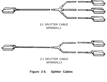
Splitter Cables
The splitter cables (Figure 2-5) connect trunk circuits from the 700A jacks to the system cabinets or 10B ETU (3:1 only).
3:1 Splitter Cable (WP90929, L1)
This cable connects the twenty-four 1-pair trunk circuits on a 700A jack to three 8-port trunk circuit packs (loop start, ground start, or DID). The connection may be either direct or through a 10B ETU. All 25-pair
connectors on the cable are male.
2:1 Splitter Cable (WP90929, L3)
This cable connects eight 3-pair tie trunk circuits on a 700A jack to two tie trunk circuit packs. All 25-pair connectors on the cable are male.
ribbon
4-port
3:1 SPLITTER CABLE WP90929,L1
2:1 SPLITTER CABLE WP90929,L3
Octopus Cables
Octopus cables (Figure 2-6) connect the station port, CPU/Memory, and STARLAN NETWORK interface circuit packs to the SIP adapters. Each cable consists of a 25-pair male connector that connects to the switch cabinet and eight modular plugs that connect to the SIP adapters. These cables are provided with all system cabinets.
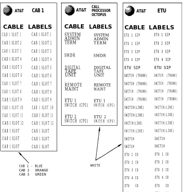
Cable Labels
A set of preprinted labels for identifying the system cabinet cables and ETU cables are provided (Figure 2-7). The system cable labels are prenumbered to identify the cabinet (1, 2, 3) and circuit pack slot (1-12, - see NOTE) and are also color-coded as follows:
Note: Because of the combined CP/Memory board in R2V1, ten slots are
available in Cabinet 1.
Cabinet No. Color 1
2 3
B l u e O r a n g e G r e e n
AT&T
CAB 1
CABLE LABELS
CAB 1 SLOT 1 CAB 1 SLOT 1
CAB 1 SLOT 2 CAB 1 SLOT 2
CAB 1 SLOT 3 CAB 1 SLOT 3
CAB 1 SLOT 4 CAB 1 SLOT 4
CAB 1 SLOT 5 CAB 1 SLOT 5
CAB 1 SLOT 6 CAB 1 SLOT 6
CAB 1 SLOT 7 CAB 1 SLOT 7
CAB 1 SLOT 8 CAB 1 SLOT 8
CAB 1 SLOT 9 CAB 1 SLOT 9
CAB 1 SLOT 1O CAB 1 SLOT 1O
CAB 1 SLOT 11 CAB 1 SLOT 11
CAB 1 SLOT 12 CAB 1 SLOT 12
CAB 1 SLOT CAB 1 SLOT
CAB 1 SLOT CAB 1 SLOT
CAB 1 SLOT CAB 1 SLOT
AT&T
CAB 1 - BLUE CAB 2 ORANGE CAB 3 GREEN
CALL PROCESSOR OCTOPUS
CABLE
SYSTEM ADMIN TERM SMDR DIGITAL TAPE UNIT REMOTE MAINT ETU 1 SWITCH (CPU) ETU 2 SWITCH (CPU)LABELS
SYSTEM ADMIN T E R MSMDR DIGITAL TAPE UNIT REMOTE MAINT ETU 1 SWITCH (CPU) ETU 2 SWITCH (CPU) WHITE
AT&T
ETU
CABLE LABELS
ETU 1 SIP ETU 1 SIP
ETU 2 SIP ETU 2 SIP
ETU 3 SIP ETU 3 SIP
ETU 4 SIP ETU 4 SIP
ETU SIP ETU SIP
SWITCH (TRUNK) SWITCH (TRUNK)
SWITCH (TRUNK) SWITCH (TRUNK)
SWITCH (TRUNK) SWITCH (TRUNK)
SWITCH (TRUNK) SWITCH (TRUNK)
SWITCH(LINE) SWITCH(LINE) SWITCH(LINE) SWITCH(LINE) SWITCH(LINE) SWITCH(LINE) SWlTCH(LINE) SWITCH(LINE) SWITCH SWITCH SWITCH SWITCH
ETU 1 CO ETU 1 CO
ETU 2 CO ETU 2 CO
ETU 3 CO ETU 3 CO
ETU 4 CO ETU 4 CO
ETU CO ETU CO
ETU CO ETU CO
Symbols Used in Figures
PREINSTALLATION REQUIREMENTS
The AT&T System 25 Reference Manual (555-530-200) provides a complete listing of System 25 equipment location requirements. Before installation begins, check the items described in this section.
Table and Backboard
Verify that an equipment table and cross-connect backboard are installed. (See Figure 2-8 for a sample layout.) The cross-connect backboard is a 48-inch by 96-48-inch by 3/4-48-inch plywood panel, mounted horizontally 30-48-inches above the floor and within 5 feet of the location chosen for the cabinets.
If wall space in the equipment room is limited, an alternate layout may be provided. If more than four 617A Panels are required, this alternate layout will require more than one 48-inch by 96-inch plywood panel. See Install Equipment Room Station Cabling for details.
Network Interface
The RJ21X network interface (CO lines) installed by the telephone company must be located within 25 feet of the system cabinets. In addition to the RJ21X network interface, an RJ2GX interface is required for tie lines. If System 25 is replacing another system and no additional Iines are required, the network interfaces used with the previous system should already be in place.
SYSTEM CABINETS (FOOTPRINT)
BACKBOARD TERMINATION
FIELD (NOTE 4)
NOTES:
1.
2.
TABLE
115V AC, 60 Hz, 15 AMP OUTLETS (HUBBELL 5262 OR EQUIVALENT) MUST BE LOCATED WITHIN 4 FEET OF SYSTEM CABINETS.
MULTIPLE CABINET SYSTEMS REQUIRE TWO QUAD OUTLETS, SINGLE CABINET SYSTEMS REQUIRE ONE QUAD OUTLET.
ALLOW AT LEAST 24 INCHES OF SPACE IN FRONT OF CABINETS. TABLE MUST BE ABLE TO SUPPORT 250 POUNDS.
BACKBOARD IS 3/4 INCHES THICK BY 48 INCHES WIDE BY 96 INCHES LONG (FOR MAXIMUM SYSTEM).
3.
4.
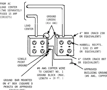
AC Power
All cabinets and any locally-connected System 25 peripheral equipment (System Administration Terminal [SAT], Station Message Detail Recording [SMDR] device, and Digital Tape Unit [DTU]) must be plugged into the common ac power outlet. This outlet must have an associated ground block connected to an approved building ground, using #6 AWG copper wire. (This ground block is the system’s single-point ground.)
A 1-cabinet system requires one quad ac outlet. A 2- or 3-cabinet system requires a second quad outlet and two separately fused 15-ampere circuits. Additional ac outlets may be needed for auxiliary equipment. All ac outlets must have the safety ground (green wire) cross-connected to the single-point ground block on the first quad outlet. (See Figure 2-9.)
Grounding
WARNING: Verify that the building ground has been provided by one of the methods listed below, that ac power uses approved building ground for its primary ground, and that all voltage limiting devices are grounded to building approved ground. Improper ground can result in equipment failures and service outages from lightning induced surges on the power lines.
An approved building ground for System 25 may be one of the following, listed in decreasing order of preference:
1.
2.
3.
Building steel.
Metal water pipe, not less than 1/2 inch in diameter. The water pipe must be part of a continuous metal pipe system connected to an underground metal water pipe that is in direct contact with the earth for 10 feet or more.
4. Ground ring consisting of at least 20 feet of bare copper conductor not smaller than
must be in direct below the earth’s
Lightning Protection
#2 AWG encircling the building. The ground ring contact with the earth and buried at least 2.5 feet surface.
System 25’s lightning protection plan involves five distinct but interdependent items required at every installation:
● Primary protection in the form of voltage limiters (typically carbon blocks or gas tubes) on all pairs that leave the building, whether aerial or buried. These devices bypass surges to approved building ground and limit potential differences between T/R pairs and building ground to less than 1500 volts.
●
A
single point ground (SPG) system in which the green wire ground (system ground) and the telephone company ground are connected to approved building ground.● Secondary protection provided within ports specifically designed for out-of-building use. Such ports can withstand 800-volt metallic (differential) and 1500-volt longitudinal (common mode) surges.
● The coupled bonding conductor must be connected between the telephone company ground at the building entrance and System 25’s SPG.
● Surge protection on the ac power to System 25.
For greater than 99 percent of all lightning strikes, the protection outlined above will do the job. However, there are a few locations where the described protection may not be sufficient. External secondary protection, located at the trunk access area of the System 25 cross-connect field, can be employed.
In addition, an AC Surge Suppressor (Tll Model 428) may be required. Local practice should be followed. The unit plugs directly into one of the quad outlets and provides a dual outlet to protected equipment. Sufficient units should be provided to protect all ac-powered equipment. Each cabinet in the system requires a protected outlet, and in addition, a protected outlet is required for each auxiliary unit, such as the SAT, a tape unit, or a printer. When a Surge Suppressor is used, all peripheral equipment directly connected to System 25 must be connected to alternating current via the Surge Suppressor.
FROM AC LOAD CENTER (TWO SEPARATELY FUSED 15 AMP
CIRCUITS) GROUND
(GREEN) (#14 AWG)
GROUND
LOAD CENTER
4" BOX (RACO 230 OR EQUIVALENT)
HUBBELL RECPTS. ( 5262 15 AMP OR EQUIVALENT)
SINGLE POINT
4" COVER (RACO 807 OR EQUIVALENT) GROUND
#6 AWG COPPER WIRE
TO CABINET NO. 1 APPROVED
GROUND BLOCK (MAX. BUILDING GROUND
LENGTH = 20 FT. ) (#6 AWG, COPPER)
BAR MOUNTED ON 4" BOX (SQUARE D
PK9GTA OR APPROVED EQUIVALENT)
Building Wiring
Building (station) wiring (must be 24 AWG or heavier) from voice and data terminals to the equipment location should already be in place. System 25 wiring requires that 4-pair circuits be distributed from the equipment location to each station’s wall jack. The SIP hardware (Figures 2-2 through 2-6), designed specifically for this purpose, is furnished with each system. Except in extraordinary circumstances, this cross-connect hardware must be used.
in unusual circumstances where the 617A Panels are not used and some other cross-connect equipment that does not provide a modular jack interface to the port circuits is used, separate 4-pair circuits must be run for the voice and data terminal at the workstation.
All examples and instructions in this manual assume that a SIP is used.
INSTALL SYSTEM CABINETS
Before beginning the cabinet installation, position the cabinet table within 2 feet of the ac power receptacle. Make sure that the cabinets are easily accessible from both the front and the back.
Position Cabinet(s)
DANGER: A fully-equipped cabinet weighs 80 pounds.
1.
2.
3.
4.
Unscrew and remove the upper rear panel of each cabinet. Do not unscrew the lower part with the 12 connectors.
Near the center of the backplane, note an address plug in one of the positions marked , 2, or 3 on the black address strip. (Position 4 is not used.) This indicates the cabinet number for software purposes. The position of the plug (1, 2, or 3) should agree with the position of the cabinet (Cabinet 1 on the bottom, etc.).
Use the CAB 1, CAB 2, and CAB 3 labels from the cable label sheets (Figure 2-7) to label each cabinet. Position the cabinet label in the box adjacent to connector 12 on the lower back panel. (The number may have already been stamped by the factory.)
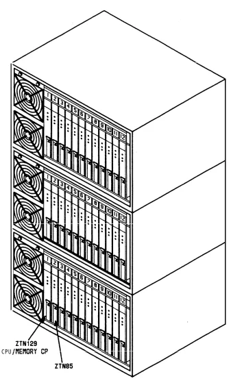
Stack the cabinets on top of one another on the stand. If there is more than one cabinet, stack Cabinet 1 on the bottom and Cabinet 3 on the top. Cabinet 1 contains the CPU/Memory (ZTN129), and Service (ZTN85) circuit packs (Figure 3-3). Do not replace the upper back panels yet.
Check Cabinet Contents
Table 2-B. Circuit Packs and Their Functions
Circuit Pack ZTN78*
TN742
ZTN79†
T N 7 3 5 T N 7 2 6 T N 7 5 8 ZTN76
ZTN77
TN753 TN760B
TN763
ZTN84
ZTN129
Supports single-line voice terminals. Supports off-premises, out-of-building, and bridged single-line voice terminals.
Supports the 7300H Series voice terminals used with a MERLIN® system. TN762B (vintage 4 or later) is an equivalent CP that can be used. Supports MET sets.
Supports data terminals and computers. Contains pooled modems.
Supports ground start trunks. TN747 is an equivalent CP that can be used.
Supports loop start trunks. TN747 is an equivalent CP that can be used.
Supports direct inward dialing trunks. (DID) Supports tie trunks.
Supports auxiliary equipment.
Provides a connection between System 25 and an associated STARLAN NETWORK.
ZTN85
Call processing/memory. Service Circuit.
Tone Detector. Z N 7 4 8
* Must not be used on out-of-building circuits.
Two fans are located on the left-hand front side of each cabinet. The cabinet’s power supply is located behind the fans; to the right of the power supply are up to 12 CPs in individual slots. Each CP is identified by a label on the front. See Figure 2-10.
1. Remove the front cover of each cabinet.
2. Note any obviously bent or otherwise damaged circuit packs.
3. Check the CPs against the customer order. In case of irregularities or damage, follow established notification procedures.
DANGER: The System 25 cabinet contents are not user serviceable. Some voltages inside the cabinets are hazardous. This equipment is to be serviced only by qualified technicians.
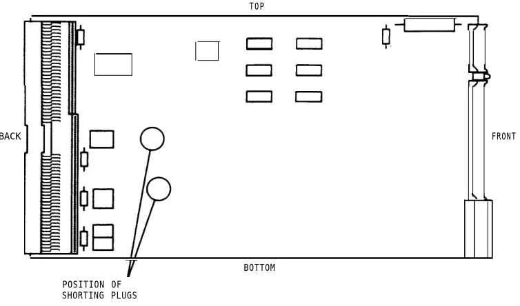
The CPU/Memory (ZTN129) circuit pack has two shorting plugs that are used for factory tests (see Figure 2-11). They should have been removed at the factory. If these shorting plugs have been accidentally left in by the factory, the system may cold start when it should warm start.
TOP
BACK
POSITION OF SHORTING PLUGS
Figure 2-11. Position of Shorting Plugs on CPU/Memory Circuit Pack BOTTOM
Required Circuit Pack Positions
The required CP positions for Cabinet 1 are:
SLOT C P
1 ZTN129
2 ZTN85
Also, all DID Trunk circuit packs should be installed in Cabinet 1.
There are no other restrictions on CP position in a single-cabinet or multicabinet system; however, you should refer to the power supply unit load requirements for the maximum unit loads for each CP type within a single cabinet.
WARNING: Be careful not to exceed unit load restrictions on each cabinet.
Label Connectors on Back Cover
Each cabinet has twelve 25-pair receptacles across the bottom of the rear panel. These connectors link the CPs inside the cabinet to the Station Interconnect Panel (SIP) and Trunk Access Equipment (TAE). The connectors are numbered from 1 to 12 and correspond to the CP slots.
Install 4A Retainer Clips
The 4A retainer clips must be installed on each of the 12 receptacles on the lower rear panel of the cabinets. To install a clip, position it and insert the legs in the cabinet as shown in Figure 2-12.
Connect Cabinets
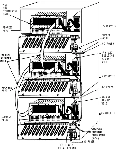
The Time Division Multiplex (TDM) bus extender cable and the intercabinet #6 AWG ground wire must be connected between cabinets. The TDM bus terminates on each side of the cabinet, and the intercabinet #6 AWG ground wire connects to the ground block at the rear of each cabinet.
Note: Make certain that the address plug is installed in the rear pin field
of each cabinet (see Figure 2-13).
TDM Bus Connections
One end of the TDM bus is terminated by resistors mounted on the ZTN129 CP. This CP is always in slot 1 of Cabinet 1. The other end of the TDM bus is terminated by a Bus Terminator that plugs into the upper pin field of the topmost carrier (which may, of course, be the only cabinet). These connections are shown in Figure 2-13.
Whenever a cabinet is added, the Bus of the bus on the new top cabinet. depending on the number of cabinets is run.
Terminator must be moved to the end This can be either slot 1 or slot 12, and how the TDM bus extender cable
When removing a Bus Terminator and TDM bus extender cable, to bend the backplane pins.
1. Verify that the Bus Terminator is in the proper position:
● Slot 12 of Cabinet 1 for 1-cabinet systems
● Slot 1 of Cabinet 2 for 2-cabinet systems
● Slot 12 of Cabinet 3 for 3-cabinet systems.
take care not
N o t e : When properly installed, the light blue stripe on the
extender cable is at the bottom of the cable and the lettering on the cable (SER=1, for example, is right side up).
TDM BUS TERMINATOR CARD
ADDRESS PLUG
PLUG
ADDRESS PLUG —
CABINET
ON/OFF SWITCH
3
AC POWER
# 6 AWG BUILDING GROUND WIRE
CABINET 2
AC POWER
#6 AWG GROUND WIRE
CABINET 1
AC POWER TO SINGLE
POINT GROUND
Ground Wire Connections
The cabinets are connected to the single-point ground with #6 AWG copper wires. (Building ground requirements are described in Preinstallation Requirements in this section.)
WARNING: The cabinet power switches must be set to off.
1. In 2- or 3-cabinet systems, connect a #6 AWG wire between the ground blocks of Cabinets 1 and 2 and Cabinets 1 and 3.
2. Connect a #6 AWG wire between the ground block of Cabinet 1 and the single-point ground. (See Figures 2-9 and 2-13.)
POWER UP AND
Separate power cords for quad outlets. Peripheral
INITIALIZE SYSTEM
each cabinet must be plugged into the designated equipment (SAT, SMDR [Station Message Detail Recording], or CAS [Call Accounting System] and DTU) collocated with the switch cabinet(s) must also be plugged into these ac outlets.
Connect Power
1. Make sure the rear panel is in place on each cabinet.
2. Connect the receptacle end of a 3-wire power cord to the plug at the rear of each cabinet.
3. Connect the power cord’s plug end to the quad ac outlet for each cabinet.
4. Recheck the electrical and ground connections.
5. Starting with Cabinet 2 or 3, turn on the power switch on each cabinet (Cabinet 1 must be last).
IMPORTANT: If power to Cabinet 1 is not turned on last, the cold start initialization may not occur properly.
6. Check to be sure that the cabinet fans are rotating.
Connect Administration Equipment
Connect the SAT and DTU to their respective modular jacks on an 858A A d a p t e r a t t h e S I P . See INSTALL CUSTOMER’S SAT for connection information. The preferred location is in the equipment room.
if the SIP has not yet been installed, connect an octopus cable to Cabinet 1, slot 1. Make temporary connections as shown in Figure 2-14 to the SAT and DTU (see Note).
Note: The direct octopus cable connections are only temporary. All
SYSTEM 25 PART OF CABINET OCTOPUS
CABLE
ZTN129 C1 (NOTE)
— — — — — —
355A SAT OR DTU
LEGEND:
ZTN129 – CPU/MEMORY CP
C1 – OCTOPUS CABLE (WP90780) 355A ADAPTER – RS-232 PLUG TO MODULAR JACK 355AF ADAPTER – RS-232 RECEPTACLE TO
NOTE:
LEG 1 CONNECTS TO SAT; LEG 3 CONNECTS
Figure 2-14. Temporary SAT and DTU
MODULAR JACK
TO DTU.
Cold Start the System
To ensure that the system recognizes the current position of the CPs, you must cold start the system before beginning initialization. A cold start causes the system to check all slots for valid CP types and assign default translations to all ports (except auxiliary trunk ports).
A limited cold start is available. The limited cold start does not assign default translations to ports. The limited cold start is useful if the customer’s dial plan is significantly different from the System 25 default pIan. YOU do not have to delete the default codes before you enter the true dial plan. See the Administration Manual (555-530-500) for a listing of default translations provided in Release 2 Version 1 systems.
The time required for a cold start depends on the number of CPs in the system, but is usually several minutes. A limited cold start takes about 30 seconds.
Follow these steps to manually start the system from the SAT:
1.
2.
3.
4.
5.
6.
Connect the SAT to the CPU/Memory CP administration port, (leg 1 of the octopus cable).
If the SAT has a selectable baud rate, set it to 1200 baud.
Be sure transmission parity is set to none, with the parity space (0).
bit set to
Turn the terminal on and press the carriage return key once or twice. On most terminals, this key is <RETURN> or <ENTER>.
After communication with the system is established, a prompt is displayed:
Enter Password ->
Enter SYSTEM25 and press <RETURN>. The main menu will now be displayed along with the prompt:
Make one selection from menu ->
7.
8.
9.
10.
11.
The system will respond with:
Action=
Enter 20 for a cold start. The system will respond with:
Save/Restore: Action=20 Data=
Enter D. The system will complete the word Data followed by the = sign.
Enter 1 for a cold start or 2 for a limited cold start. The system will respond with:
Save/Restore: Action=20 Data=1 (or Data=2)
You are about to initiate a cold start
c to continue, any other key to abort
Enter c to initiate the cold start.
Cold and warm starts both display the same type of information on the SAT. This consists of a listing of the version of the firmware loaded in the CPU/Memory CP, followed by a configuration listing of all CPs recognized by the system. The CPU/Memory CP is not in the configuration listing; however, it is located in slot 1 of Cabinet 1.
Table 2-C provides a listing of SAT messages that may be displayed during a cold or warm start. The displayed message is a result of CP occupancy, type, and port translations.
Table 2-C. Displayed SAT Messages During Cold or Warm Restart
Circuit Pack (CP) Port Displayed
In Slot Translated Message
No Yes Missing *
Yes No CP Type Listed †
Yes Yes CP Type Listed
Yes Yes (doesn’t match Mismatch *
physical CP)
Yes (Unsupported Yes or No Illegal
CP Type)
* Warm restart only.
The SAT message for a cold or warm start appears after the system has performed all self-tests and reading of its configuration. Typical cold start SAT message is as follows. The example is for a 2-cabinet system.
Typical Release 2 Version 1 Cold Start Message
RESTART TS ROM pair FC ROM pair FC ROM pair FC ROM pair COLD START
Default Password in Effect SLOT 1 2 3 4 5 6 7 8 9 10 11 12
1: version 3.5 * 1: version 3.13 * 2: version 3.13 * 3: version 3.13 *
CABINET 1 CABINET 2 CABINET 3
ZTN85 06 TN753 04
ZTN79 03 TN760B 05
ZTN79 03 TN760B 05
ZTN79 03 TN760B 05
ZTN79 03 TN760B 05
ZTN78 02 ZTN78 02 ZTN78 02 TN747 03 TN747 03 TN748 06
* This is important information that should be noted in trouble reports.
Message: Press <RETURN> to continue.
E n t e r < R E T U R N > . The system will respond with the administration prompt:
SYSTEM 25 ADMINISTRATION (CPU/Memory release information)
Check Performance of Cabinet Components
Each CP has three colored LEDs on the front panel that indicate whether it is functioning properly or not. When a cold start is performed, the system undergoes a series of self-tests and loads default translations.
Upon initial power application, each CP tests itself. The red LED on the CP lights to indicate that the test is in progress. Once the CP passes its initial tests, the red LED goes off. Then, after the main processor recognizes the CP and can communicate with it, the green LED lights. When all green LEDs are lighted, the testing and loading Process is complete. This Process takes about 3 minutes.
1. Make sure that both fans in each cabinet are on and operating.
2. Make sure that the green LED on the power unit behind the fan assembly is lighted.
Table 2-D.
Circuit Pack LED Status Indications
Circuit Pack Type LEDs if Normal LEDs if Failed
Service Circuit (ZTN85) Steady Green and Steady Red or
Flashing or Amber Off
Steady Amber
CPU/Memory (ZTN129) Flashing Green Steady Green or Off
All Other Steady Green Steady Red
(Amber Also lighted (see Note below) when CP in use)
Note: The red and green LEDs can both be lighted at the same time. In
If all the CPs are operating properly, only the LED on the CPU/Memory CP should be flashing. If any other CP has a no-lighted LED, the CP may need to be reseated. Exception: Auxiliary Trunk CP’s green LED remains dark until at least one port on the CP has been translated. (These ports have no default translations.)
Except for the CPU/Memory CP and Service Circuit CPs, power can be left on while a CP is reseated. To reseat a CP, do the following:
1.
2.
3.
4.
5.
6.
7.
See WARNING. Make sure your hands are clean and dry. Put on a wrist grounding strap, and clip it to the grounding block at the rear of the cabinet.
WARNING: Static electricity can damage a CP.
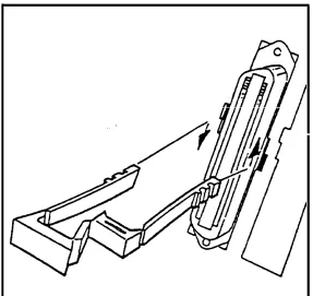
With your thumb, pull up on the latch pin of the removal lever. (See Figure 2-15.)
When the latch pin is up, pull the removal lever down until it stops, at an angle of about 30 degrees to the floor.
Tugging hard, pull the CP out a few inches. Leave it out for at least 30 seconds, and then push it back firmly into its slot. When it is almost back in place, you’ll feel resistance. The removal lever will start to return to its vertical position.
Push the lever all the way to vertical until it catches on the latch pin.
After the power-up, repeat this process for each CP with dark LEDs (except ZTN129 and TN763s).
Figure 2-15.
ALARM LED (RED)
READY TO-USE LED (GREEN) BUSY LED (YELLOW)
LATCH PIN
LOCKING LEVER
Typical System 25 Port Circuit Pack
Report Problems
Follow local procedures to report faulty or damaged equipment.
INSTALL CROSS-CONNECT EQUIPMENT
Before starting, familiarize yourself with the following equipment described in CROSS-CONNECT EQUIPMENT DESCRIPTION:
● Trunk Access Equipment (TAE)
— 700A-110-B1-25 or 700A-66-B1-25 Wiring Jacks
— 10B Emergency Transfer Units
● Station Interconnect Panel (SIP)
— 617A Panels
— 858A or Z210A1 Adapters
— 50A Fanning Strips.
Figure 2-16 shows a typical SIP and TAE backboard layout. Figure 2-17 shows an alternate layout that can be used when horizontal wall space is limited. These layouts can be reversed when the switch cabinet(s) must be installed to the right of the backboard.
Install TAE, 617A Panels, and Fanning Strips
To install this equipment, proceed as follows:
1. For each RJ21X and RJ2GX network interface, install one 700A Jack 1/2-inch from the edge of the backboard closest to the switch cabinet(s).
2. Mount the first 617A Panel.
4.
5.
6.
7.
8.
9.
10.
11.
If required, mount a second 50A Fanning Strip above the first.
Mount the first 10B Emergency Transfer Unit (ETU) in the position shown in Figure 2-16 or Figure 2-17. Overlap the edges of the ETU and the panel so that the same screws will go through the overlapped key slots.
Mount the remaining 617A Panels. Overlap the panels to conserve space and to reduce the number of screws required: however, do not mount more than three panels on either side of the 50A Fanning Strip.
If required, install the second ETU above the first.
if additional ETUs are required, install them close to the 700A Jacks (Figure 2-16). If the alternate SIP arrangement (Figure 2-17) is used, install additional ETUs above the second ETU.
Using a felt-tipped pen, letter the adapter columns (A through J) on the 617A Panels, starting with the left side. For the alternate arrangement, start with the left side on the lower row.
Using a #12 AWG ground wire, connect the ground points on the ETUs (screw terminal on the upper left side) and link them to the single-point ground.
FIRST
53"
10B ETU
TO BLDG WIRING
TO BLDG WIRING
700A 700A ADD'L 617
A
PANEL
ADD'L 617A PANEL ADD'L 617A PANEL ADD'L 617A PANEL
ADD'L ETU ADD'L ETU
9"MIN
D-RINGS AS REQ'D
FIRST 50A
FREE HANGING
FANNING STRIP
FLOOR
FlRST 617A PANEL
30”
OCTOPUS CABLE WITH 65" FREE
LENGTH
Figure 2-16.
1/2” PLYWOOD BACKBOARD FIRST 10B ETU ADD’L 700A BLOCK TO BLDG WIRING ADD'L
E T U
ADD'L 700A BLOCK
ADD'L 700A BLOCK
A D D ' L 5 0 A ADD'L 700A
BLOCK
ADD'L 6 1 7 A PANEL
A D D ' L 617A PANEL 700A BLOCK 700A BLOCK TO SWITCH CABINET
NOTE: GREATER THAN
3 3 ” 48” FOR 5-PANEL
ARRANGEMENT
FlRST
617A PANEL
TO BLDG WIRING TO BLDG WIRING
ADD’L
ADD'L ETU ADD’L
617A 617A PANEL ADD'L PANEL ETU FIRST 50A FANNING STRIP FREE HANGING OCTOPUS CABLES WITH 77” FREE LENGTH FLOOR 56 1/8” 9”MIN 27”MIN
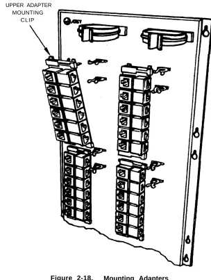
Mount 858A or Z210A1 Adapters
To install these adapters, proceed as follows:
1. Using a wide blade screwdriver, pry off the upper adapter mounting clip on the 617A Panel (Figure 2-18).
2. Fit the mounting clip on the top of the adapter.
3. Fit the adapter in the slot of the lower mounting clip.
4. Press the upper mounting clip back into the panel.
UPPER ADAPTER MOUNTING
INSTALL MODULAR BULK POWER SUPPLY
(Optional)
The 346 Modular Bulk Power Supply (MBPS) is a cost-effective and flexible alternative to the KS-22911 power supply. The 346 MBPS can be used where the wall-mounted (outlet) KS-22911 power supply cannot be used or where multiple KS-22911 power supplies are required.
The 346 MBPS consists of the 346A Power Unit and 346A1 Power Panel. Up to three 346A Power Units can be mounted in a power panel. Each 346A Power Unit is capable of powering four terminals with adjuncts (“10 w” position), for a total of 12 terminals. Terminals powered by the 346A Power Unit can be located up to 1000 feet from the unit.
The 346 MBPS should be installed near the SIP. Service to the ac outlet powering the 346 MBPS must be a dedicated (nonswitched) 20-ampere line. A maximum of four power panels can be connected to the 20-ampere line. The AC Surge Suppressor (T11 Model 428) should be used with the 346A1 Power Panel.
INSTALL EQUIPMENT ROOM TRUNK CABLING
As mentioned earlier, all outside lines must be connected to the system through connectorized network interfaces. These interfaces are connected to wall-mounted trunk access equipment (TAE), and from there to the cabinets.
Connect Network Interfaces to TAE Blocks
The trunks and off-premises stations from the network interface must be cut down on the TAE’s connecting blocks so that the trunks are grouped by type (loop start, ground start, DID, and tie) at the connecting block. Each connecting block can handle up to three groups of eight trunks or two groups of four tie trunks.
Tie trunks must be segregated on a separate block because a different splitter cable is used. Also, off-premises stations must be segregated on one 700A Jack.
The first five trunks in each group of eight (loop start or ground start trunks only) can be connected through an ETU to five power failure transfer stations. However, all eight trunks are connected to, and pass through, the ETU.
The ETU also supports a DID make-busy function to the central office’s extra pair (if required). Relay contacts for the DID make-busy function appear on the 25th pair on the TAE block. The relay contacts are normally open. When power fails, the contacts close, making all DID trunks appear busy to the central office. This prevents the central office from taking the DID trunks out of service.
A maximum of four ETUs are supported. For a system with more than one ETU, apportion the emergency transfer trunks so that they are in the first subgroup of five in each subgroup of eight trunks on a connecting block.
1. Connect an A25D 25-pair single-ended cable to each network interface receptacle.
2. Cut down the other end of each cable on the top terminal row of a 700A Jack in groups of eight trunks (four for tie trunks), as described above (see Note). Cut down the DID make-busy pair (if provided) to terminals 49 and 50 on the block.
N o t e : F a c i l i t i e s u s e d f o r o f f - p r e m i s e s s t a t i o n s , m u s t b e
segregated on one 700A Jack.
Connect Cabinets to TAE Blocks
The connections between the cabinets and the TAE blocks are made using connectorized splitter cables. Make sure that each trunk group on each connecting block is connected to the correct type of CP, as shown in Table 2-E.
Central office trunks associated with emergency transfer and off-premises stations (OPSs) are not connected directly to the cabinets. If you are installing trunks that are to be used for OPS, see Off-Premises Stations in this part. Also, to complete the procedure for installing trunks used for emergency transfer, you must go to Install Emergency Transfer Units (ETUs) in this part.
Table 2-E. Trunk Circuit Packs
Circuit Pack Trunk Type
ZTN76 Ground Start
ZTN77 Loop Start
TN753 DID
TN760B Tie
Connect Ground Start, Loop Start, and DID Trunks
A 3:1 connectorized splitter cable, WP90929, L1, is required to connect the 700A Jack to the cabinet for these trunks.
1. Using the cable label sheets provided (Figure 2-7), label the back of the hood of each of the connectors (1, 2, and 3) on the three legs of the splitter cable (see Note). Use an appropriate cabinet and slot number label (CAB 1 SLOT9, for example).
Note: If one or more of the legs contain trunks that are to be
2.
3.
4.
5.
On connector 0, install labels that correspond to those used on each of the three splitter cable legs. Position the labels so that they will be clearly visible after the cable is plugged in.
Plug connector 0 into the 700A Jack.
Except for legs containing trunks to be used for emergency transfer, connect connectors 1, 2, and 3 to the cabinet. Connect only to ZTN76 Ground Start, ZTN77 Loop Start, or TN753 DID CPs.
Repeat procedure as required.
Connect Tie Trunks
A 2:1 connectorized splitter cable, WP90929, 700A Jack to the cabinet for tie trunks.
L3, is required to connect the
1.
2.
3.
4.
5.
Using the cable label sheets provided (Figure 2-7), label the back of the hood of each of the connectors (1 and 2) on the two legs of the splitter cable. Use an appropriate cabinet and slot number label (CAB 1 SLOT8, for example).
On connector 0, install labels that correspond to those used on each of the two splitter cable legs. Position the labels so that they will be clearly visible after the cable is plugged in.
Plug connector 0 into the 700A Jack.
Plug connectors 1 Tie Trunk CP.
Repeat procedure
and 2 into the cabinet. Connect only to a TN760B
Connect Coupled Bonding Conductor (CBC)
Each network interface (RJ21X or RJ2GX) is associated with a service entrance (protector block) ground. A CBC should be connected to this ground. If the local telephone company has not run a CBC up to the network interface, you should run it yourself. Use #12, #14, or #16 AWG wire. Start the CBC at the protector block ground, and run it as close as possible to the facilities cable. If possible, tie wrap the CBC to the facilities cable. Do not use spare pairs in the telephone company cable for this purpose.
Consideration should be given to installing secondary protection on each out-of-building facility connected to the TAE if any of the following conditions exist:
● The service entrance (protector block) ground is not properly installed (bonded to building ground, for example).
● The local telephone company does not permit access to the protector block.
● High-voltage surge
Install the CBC as follows:
1.
2.
3.
Connect one end interface.
protection is not provided.
of the CBC to the ground point at the network
Wrap the CBC loosely around the cable from the network interface to the TAE
possible, tie
Connect the Figure 2-13.
and then around a splitter cable to the cabinet. If wrap the CBC to the cables.
INSTALL EQUIPMENT ROOM STATION CABLING
System 25 is connected to the building (station) wiring in two stages. First, the building wiring is connected to the Station Interconnect Panel (SIP). Then, the octopus cables from the back of the cabinets are connected to the SIP.
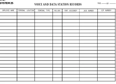
Accurate documentation during installation is essential to the performance and maintenance of System 25 and will make initialization and administration much easier to perform. The Voice and Data station Records Form (Figure 2-19) traces the connection from the workstation where the voice or data terminal is located to the SIP. Obtain this form from the Implementation forms that the TC or TCSS has prepared for system initialization. When you install the station wiring, enter the jack number and SIP number for each terminal to identify each end of the cable run. Number and label the station jacks per local practice.
AT&T SYSTEM 25
VOICE AND DATA STATION RECORDS PAGE OF
EMPLOYEE NAME TERMINAL LOCATION TERMINAL TYPE POC/DOC PORT ASSIGNED* JACK NUMBER SIP NUMBER*
* FROM SYSTEM 25 INSTALLER
Connect Building Wiring to SIP
The type of building wiring termination determines what types of adapters are used. TWO types are supported: 4-pair cable (cut down) and modular jack. Any combination of adapters may be mounted on a 617A Panel. Cluster the connection on the SIP by voice terminal type: single-line, 7300H Series*, Multibutton Electronic Telephone (MET), and voice/data.
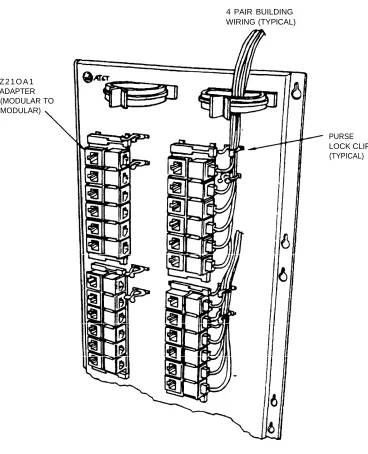
Modular Plug Termination
Each 4-pair modular plug supports one station (Figure 2-20). It connects to a modular jack in a 2210A1 Adapter.
1.
2.
3.
4.
5.
6.
7.
Run the 4-pair cable through the rings at the top of the 617A Panels.
Connect the plug to any 2210A1 Adapter.
Feed the cable into the two purse lock clips at the adapter.
Using a felt-tipped pen, record the building wiring destination on the adapter’s grey modular jack.
Repeat the process until all of the 4-pair building cables are connected to the SIP. Some spare adapters should be left on the SIP to accommodate growth.
Twist the purse lock clips closed.
Z 2 1 O A 1 ADAPTER (MODULAR TO MODULAR)
4 PAIR BUILDING WIRING (TYPlCAL)
PURSE LOCK CLIP (TYPICAL)
4-Pair Cable Terminations
Each 4-pair cable supports one station (Figure 2-21). It connects to a wiring block on a 858A Adapter.
1.
2.
3.
4.
5.
6.
Run the 4-pair cable through the rings at the top of the 617A Panels.
Cut down the leads starting with pin 1 of the wiring block located beside the modular jack (Figure 2-21).
Wiring Block DIW Cable Pin No. Color Code
1 W-BL
2 BL-W
3 W-O
4 O-W
5 W-G
6 G-W
7 W-BR
8 BR-W
Using a felt-tipped pen, record the building wiring destination on the wiring block caps.
Repeat the process until all of the 4-pair building cables are connected to the SIP. Some spare adapters should be left on the SIP to accommodate growth.
Feed the six cables for each adapter into the two purse lock clips at the adapter. Twist the clips closed.
4 PAIR BUILDING WIRING (TYPICAL) 858A ADAPTER
(MODULAR TO 110 CUT DOWN BLOCKS)
AT&T
PIN 1
PIN 8’
PURSE LOCK CLIP (TYPICAL)