*Corresponding author: [email protected]
Towards a New Framework for TPM Compliance Testing
Usama Tharwat Elhagari1*, Bharanidharan Shanmugam2, Jamalul-lail Ab. Manan3
1Faculty of Computing, Universiti Teknologi Malaysia (UTM), Malaysia 2
Advanced Informatics School, Universiti Teknologi Malaysia (UTM), Malaysia 3MIMOS Berhad, Malaysia
Abstract
Trusted Computing Group (TCG) has proposed the Trusted Computing (TC) concept. Subsequently, TC becomes a common base for many new computing platforms, called Trusted Platform (TP) architecture (hardware and software) that, practically, has a built-in trusted hardware component mounted at the hardware layer and a corre-sponding trusted software component installed at the operating system level. The trusted hardware component is called Trusted Platform Module (TPM) whose specifi-cation has been issued by TCG group and it is implemented by the industry as a tam-per-resistant integrated circuit. In practice, the security of an IT TPM-enabled system relies on the correctness of its mounted TPM. Thus, TPM testing is urgently needed to assist in building confidence of the users on the security functionality provided by the TPM. This paper presents the state of the art of the modelling methods being used in the TPM compliance testing. Finally, the paper proposes new framework criteria for TPM Testing that aim at increasing the quality of TPM testing.
Keywords. Trusted Platform Module; Compliance Testing; Modelling
1
Introduction
Recently, software on computing platforms has become increasingly complex leading to a large number of potential vulnerabilities. Consequently, protecting information technology systems through software-based mechanisms has become increasingly more unable to solve all security problems there in. To mitigate this issue, hardware-based embedded security solutions have been used in the information technology industry. Among the key advances, Trusted Computing
Platform Alliance (TCPA), which was later replaced by the Trusted Computing Group (TCG), proposed the Trusted Computing (TC) concept. Subsequently, TC became the common base for many new computing platforms, called Trusted Platform (TP) architecture that, practically, has a built-in trusted hardware
IRICT 2014 Proceeding
component at the physical level and corresponding trusted software component at operating system level. The trusted hardware component is called Trusted Platform Module (TPM) whose specification was issued by the TCG group and is implemented by industry as a tamper-resistant integrated circuit. TPM is dedicated
to performing cryptographic functionality and to securely store cryptographic keys and secrets.
Since the last couple of years, hundreds of millions of PC laptops and desktops have been equipped with TPM chips. In fact, there are many different vendors that
produce TPM chips, such as Atmel, Infineon, Broadcom, Sinosun and STMicroelectronics / Winond, and, of course, with different modes of implementation. This implies that there is an urgent need to have a testing methodology that can help security application developers and end-users to verify the compliance of their TPM-enabled systems with respect to TCG specifications
[1],[ 2].
Past research works in the area of TPM testing fall into two broad categories, namely; compliance testing, [2-8] and security analysis on the TPM specifications, [2], [9-15]. This paper presents several modelling methods which are in the domain
of TPM compliance testing. Recent efforts show that many TPMs available in the market are non-compliant to the TCG specification [2-8]. At this point, it is worth mentioning that China has its own specification and its trusted hardware component is called Trusted Cryptography Module (TCM). The TCM chip has been specified and manufactured by China. In [16], it was concluded that there was a gap between the TCM implementations and the Chinese specification. This paper presents the state of the art of the modelling methods in the TPM compliance testing. We begin
2
Modelling Methods of TPM Specifications
There are mainly three methods that have been used in modelling the TPM
specifications. The TPM testing was first introduced in [1] and [17], however, the method is informal. On the other hand, the two methods discussed in [4], [5], [16] are formal and based on state machine theory namely, Finite State Machine (FSM) and Extended Finite State Machine (EFSM). In the next sub-sections a brief discussion on the following three methods; informal modelling, FSM-based modelling and EFSM-based modelling is presented.
2.1 Informal Modelling
The TPM compliance testing was first introduced [1], [17] in which TPMs from different vendors were evaluated. In informal modelling, testing is conducted in two
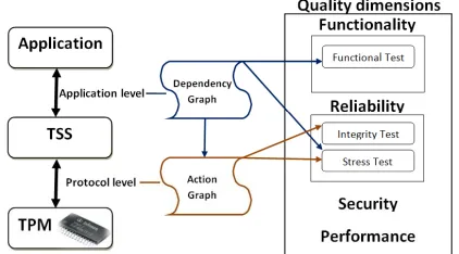
levels and two quality dimensions, as shown in Figure 1.
Figure 1. Compliance Testing Levels and Quality Dimentions of TPM
Firstly, the Compliance Testing Levels consists of the application level and the protocol level. At the application level, the TPM is tested from real application standpoint to test the TPM functionality. The protocol level is dedicated to test the TPM's commands with respect to the data structures. Secondly, in Compliance TPM
Testing there are four core quality dimensions namely, functionality, reliability, security and performance. Nevertheless researchers in [1], [17] considered only two quality dimensions, which are functionality and reliability. Notably, under the functionality dimension, only a function test is conducted. Whereas under the reliability dimension, integrity test and stress test are conducted. In this paper, the
Two other aspects of the Compliance TPM testing include, TPM behavior which is examined via function test and TPM behavior upon failures which is examined using the integrity tests. Yet another aspect is the stress tests which examine TPM behavior under extreme conditions . Here, we emphasize and focus on their method
test the data structure of a single command, many test cases are needed to test the command parameters. Thus to generate test cases for each command, the execution command is modeled as a state transition into a return code, as shown in Figure 2.
Figure 2. TPM Command Execution Model
It is observed that the number of test cases in compliance testing is an issue. To mitigate this issue, the input parameters of the TPM commands are categorized into four different categories based on input parameters which are described below [1], [17]:
Valid: they are acceptable inputs and allow TPM to correctly and successfully process the command. Consequently, the return code must be TPM_SUCCESS.
The following three categories should return code indicating an error:
Illegal (A): these are inacceptable inputs as they have either wrong data structure or unspecified values, which are not stated by TPM specifications,
Invalid (B): these are inacceptable inputs as their values are wrong or meaningless values.
Unsupported (C): these are inputs with values stated by TPM specifications but not acceptable in the context of the command.
The steps of the integrity tests at the protocol level are as follows [1], [17]:
1. Study in detail the TPM specifications.
3. From the Dependency Graph draw the action graph which shows the required execution order of the TPM commands for successful individual TPM com-mands execution.
4. Define the state(s) at which the command (under test) is allowed to execute. 5. Define the TPM return code(s) for those state(s) at which the command is not
allowed to execute.
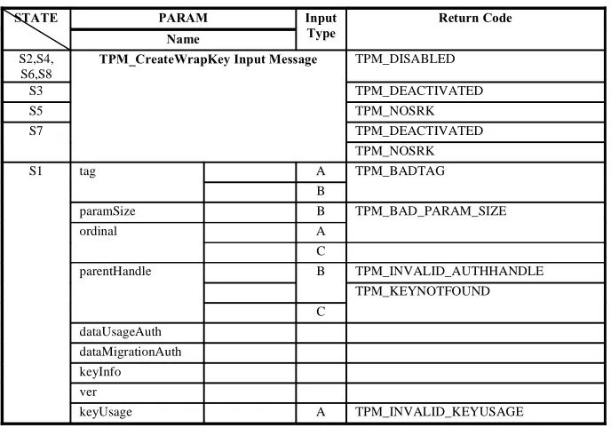
6. Construct a table/graph showing all the command parameters after manipula-tion and the related return codes. Table 1 shows TPM_CreateWrapKey as an example.
7. Execute all the commands required, indicated by the action graph, for the suc-cessful command execution.
8. Send the command input message with only one manipulated parameter to the TPM.
9. Compare the return code from the TPM with the expected one as stated in the table/graph.
10. Repeat step 9 and 10 for each manipulated parameter.
11. If all the return codes from the TPM match the expected ones then the imple-mentation of the command under test is complaint with TPM specification, based on integrity test only.
12. Repeat step 2 up to step 11 for TPM commands, stated on the TPM specifica-tions.
Researchers [1], [17] are considered as the founder of TPM compliance testing and has contributed valuable knowledge and experience significantly in TPM testing. From their past works we know that some TPM implementations which are from
(Infineon, Atmel, and ST STM 19 WP 18) were found to be incompliant with TCG specification and have security related bugs. However, the method used in
determining the compliance was still informal [16] and, furthermore its generation of test cases was not automatic and the test method needs to be reviewed and improved so that it becomes more systematic [2].
It is generally known that manual generation of test cases is an expensive, error-prone and time consuming process. Nowadays, with the improvement of TPM implementations, the informal method and manual generation of test cases might not be so effective in dealing with greater number of cases of incompliance of TPM implementations.
Mealy machines and Moore machines are two types of finite state machines or finite automata. These are widely used to model finite state systems in different areas such as communication protocols and sequential circuits.
Definition 1: a deterministic finite state machine (FSM) D is a six-tuple:
init ) where S, I , and O are finite and non-empty sets of states, in-put alphabet and outin-put alphabet, sinit is the initial state,
the functions of state transition and output, respectively.
The conformance of system implementation to the system specification can be tested by using FSM. This problem is called conformance testing or fault detection problem [18]; at which two FSMs are given: a specification machine SPEC and im-plementation machine IMP. We can only observe the behavior of IMP that is a black box.
To test the conformance of an implementation under test IUT to its specification, it is needed to generate test cases from the SPEC model and then apply these test cases to the IUT. Test cases can be generated automatically from SPEC. A test case contains input and expected output. Therefore IUT conforms to its specification if it passes all the test cases.
Table 1. Return codes for TPM_CreateWrapKey after manipulating its Input-Parameters
STATE PARAM Input
Type
Return Code Name
S2,S4, S6,S8
TPM_CreateWrapKey Input Message TPM_DISABLED
S3 TPM_DEACTIVATED
S5 TPM_NOSRK
S7 TPM_DEACTIVATED
TPM_NOSRK
S1 tag A TPM_BADTAG
B
paramSize B TPM_BAD_PARAM_SIZE
ordinal A
C
parentHandle B TPM_INVALID_AUTHHANDLE
TPM_KEYNOTFOUND
C
dataUsageAuth
dataMigrationAuth
keyInfo
ver
C
keyFlags A TPM_BAD_PARAMETER
C
authDataUsage A TPM_BAD_PARAMETER
C
algorithmParms A TPM_BAD_KEY_PROPERTY
C
TPM_NOTFIPS
algorithmID
authHandle B TPM_AUTHFAIL
C TPM_INVALID_AUTHHANDLE
authLastNonceEven
nonceOdd
continueAuthSession
pubAuth B TPM_AUTHFAIL
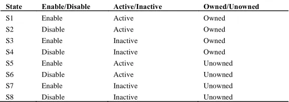
Researchers in [4], [5] modelled the TPM operational states, as shown in Table 2, and the commands of TPM based on deterministic finite state machine. There are four FSM models have been constructed which include the TPM operational states, TPM disabled-command suite, TPM deactivated-command suite and TPM un-owned-command suite.
Table 2. TPM Operational States
State Enable/Disable Active/Inactive Owned/Unowned
S1 Enable Active Owned
S2 Disable Active Owned
S3 Enable Inactive Owned
S4 Disable Inactive Owned
S5 Enable Active Unowned
S6 Disable Active Unowned
S7 Enable Inactive Unowned
S8 Disable Inactive Unowned
We give an explanatory example for modelling TPM specifications based on FSM; Figure 3 shows the FSM model of the eight TPM operational states. This example is based on the methodology employed in [4], [5]. The parameters of the FSM model are as follow:
D0 = (S0, I0, O0 0 0, sinit0 )
I0={ TPM_OwnerSetDisable, TPM_PhysicalDisable, TPM_PhysicalSetDeactivated, TPM_SetTempDeactivated, TPM_OwnerClear, TPM_ForceClear,
TPM_PhysicalEnable, TPM_TakeOwnership}
O0= {S } where S means that the TPM successfully has executed the related com-mand. sinit0= s5
Bread-First Search has been used to generate test cases from D0.
Figure 3. FSM Model for the TPM Operational States
Basically, FSM is used to model the control portions of system specification. This could be the main weakness of FSM as system specification normally contains data dependencies between the specification parts; which means that FSM is not power-ful enough to model concrete systems in a concise way [18]. Consequently, FSM model may have issues such as state explosion as the number of states increases rap-idly [19] and FSM is not realistic in most practical situations [20]. According to the
data from each other and a successful command execution may need other command(s) that have been successfully executed. Therefore, modeling the TPM specification using FSM, taking into account control and data dependencies between the commands, could re-sult in impractically huge model and consequently having state explosion problem.
e-termine the behaviors of the TPM implementation.
2.3 EFSM Modelling
Definition 2: An EFSM is a six-tuple [16, 19] (S, s0, I, O, T, V) where S is a non-empty finite set of states, s0 S is the initial state, I and O are non-empty finite sets of input and output interactions, T is a non-empty finite set of transitions and V is a non-empty finite set of variables. t T is a six-tuple (si, se, x, c, y) where si, se S denote the initial and terminating states of t, respectively, x I is the input interac-tion of t, c is a logical expression representing a condiinterac-tion of t and expressed in terms of the variable of V, y O is the output interaction of t.
EFSM-Based specification modelling was used in trusted computing by [16], where the authors modelled the specifications of the Trusted Cryptography Module (TCM) by EFSM. Firstly, the dependencies between the TCM commands were de-fined and, consequently, a dependency graph was drawn. Secondly, an EFSM model was constructed and test cases were generated for the EFSM model. The authors mentioned that the test case generation was not fully automatic. Finally, the TCM compliance testing was conducted in two layers, namely: command-level and func-tion level. The former was used to test the TCM reliability, i.e. its behaviour when receive legal-manipulated command message, as well as testing the TCM robustness where the behaviour of the TCM was tested by sending illegal-manipulated com-mand message. In the latter, functionality test was conducted for testing the TCM functions.
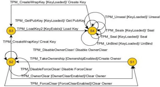
To give an illustrative example of the EFSM modelling of the TPM specifica-tions, Figure 4 shows EFSM model for a portion of the TPM specification, storage functions module and some commands of the admin ownership module sub-module. This example adopts the methodology used in [16]. The EFSM model was constructed based on the research work of and the TPM specification version 1.2, level 2 revision 116. As can be seen from Figure 4, the parameters of the EFSM model are as following:
S= {S1, S2, S3, S4}; s0= S1;
I= { TPM_TakeOwnership, TPM_OwnerClear, TPM_ForceClear,
TPM_DisableOwnerClear, TPM_DisableForceClear, TPM_Seal, TPM_Unseal, TPM_Unbind, TPM_CreateWrapKey, TPM_LoadKey2, TPM_GetPubKey, TPM_Sealx}
O= {Create Owner, Clear Owner, Create Key, Disable ForceClear, Disable Owner-Clear, Load Key, Unseal, Seal, UnBind, Get PubKey}
V= {Ownership Enabled, KeyLoaded, KeyExists, OwnerClearEnabled, ForceClearEnabled}
Figure 4. EFSM Model for Storage Functions and Admin Ownership sub-modules
The EFSM-Based specification modelling in [16] has made some improvement to the model proposed in [4, 5] in modelling and generating test cases. However, it needs lacks the automatic generation of test cases. Furthermore, in order to use this method in TPM compliance testing it needs to involve the internal TPM data, such as flags, as variables to represent the relationship among the TPM commands.
3. Conclusion
Trusted computing (TC) is a promising technology for enhancing the security of computer systems and networks. TCG issued specifications for TC technology which is called TCG specifications. We emphasize on the TPM specifications. Based on past works it is discovered that there is a gap between some TPM imple-mentations and the TPM specifications. This gap may cause the TPM component to fail in performing its security functionality and consequently may result in failing the security of its mounted system. Therefore, there is an urgent need to test the compliance of TPM implementation with reference to its specifications. In this pa-per, we report on some progress of the research works in the field of TPM testing have been achieved. The two major contributions of our work are on TPM compli-ance testing and security analysis on TPM specifications. In complicompli-ance testing of TPM, we presented the three modelling methods, namely, informal, FSM and EFSM. The main problem of these three methods is that there is a high possibility that it might cause state space explosion. Furthermore, the existing TPM compliance testing framework that we have referred to in the literature so far, conducted their tests based on test cases pre-generated earlier. In other words, a complete test suite must first be derived completely before conducting the TPM compliance testing. This approach is referred to as batch-mode testing.
empha-sized as a quality dimension in the exiting Framework for TPM Testing. We have discussed and highlighted the urgent need to enhance the current TPM testing frameworks to achieve higher quality TPM testing.
For future work, we propose a new framework for TPM Testing that has several features. Firstly, it should have capacity to generate random test cases on-the-fly. This helps in alleviating the state space explosion problem and improves the quality of testing. Secondly, it should posse other quality dimensions such as automatic se-curity testing. Furthermore, it should be suitable for the TPM stakeholders such as normal TPM users who have abstract knowledge about TPM.
References
1. Ahmad-Reza, S., Marcel, S., Christian, S., ble, Christian, W., and Marcel, W. "TCG inside?: a note on TPM specification compliance" Proc. of the first ACM workshop on Scalable trusted computing, Alexandria, Virginia, USA2006, pp. 47-56, 2006
2. Zhang, H., Yan, F., Fu, J., Xu, M., Yang, Y., He, F., and Zhan, J. "Research on theory and key technology of trusted computing platform security testing and evaluation", SCIENCE CHINA Information Sciences, 2010, 53, (3), pp. 434-453 3. Sadeghi, A.R. "Challenges for trusted computing", Challenges for trusted
computing (Springer Verlag, 2006, edn.), pp. 414, 2006
4. Zhang, H., Luo, J., Yan, F., Xu, M., He, F., and Zhan, J. "A practical solution to trusted computing platform testing", A practical solution to trusted computing
platform testing (Inst. of Elec. and Elec. Eng. Computer Society, 2008, edn.), pp. 79-87, 2008
5. Zhan, J., Zhang, H., Zou, B., and Li, X. "Research on automated testing of the trusted platform model", Research on automated testing of the trusted platform
model (Inst. of Elec. and Elec. Eng. Computer Society, 2008, edn.), pp. 2335-2339, 2008
6. Xu, M.-D., Zhang, H.-G., and Yan, F. "Testing on trust chain of trusted computing platform based on labeled transition system", Jisuanji Xuebao/Chinese Journal of Computers, 32, (4), pp. 635-645, 2009
7. He, F., Zhang, H., Wang, H., Xu, M., and Yan, F. "Chain of trust testing based on model checking",Chain of trust testing based on model checking (2010, edn.), pp. 273-276, 2010
8. Chen, X.F. "Formal analysis and testing of trusted platform module", Jisuanji Xuebao/Chinese Journal of Computers, 32, (4), pp. 646-653, 2009
9. Lin, A.H. Automated Analysis of Security APIs, Massachusetts Institute of Technology, 2005
11. Chen, S., Wen, Y., and Zhao, H. "Formal analysis of secure bootstrap in trusted computing",Formal analysis of secure bootstrap in trusted computing (Springer Verlag, 2007, edn.), pp. 352-360, 2007
12. Delaune, S., Kremer, S., Ryan, M.D., and Steel, G. "Formal Analysis of Protocols Based on TPM State Registers", Formal Analysis of Protocols Based on TPM
State Registers (2011, edn.), pp. 66-80, 2011
13. Degano, P., Etalle, S., Guttman, J., Delaune, S.p., Kremer, S., Ryan, M., and Steel, G. "A Formal Analysis of Authentication in the TPM" Formal Aspects of Security and Trust (Springer Berlin Heidelberg), pp. 111-125, 2011
14. Namiluko, C., and Martin, A. "An abstract model of a trusted platform" Proceedings of the Second international conference on Trusted Systems, Beijing, China, pp. 47-66, 2011
15. Bai, G., Hao, J., Wu, J., Liu, Y., Liang, Z., and Martin, A. "TrustFound: Towards a Formal Foundation for Model Checking Trusted Computing Platforms" FM 2014: Formal Methods (Springer), pp. 110-126, 2014
16. Li, H., Hu, H., and Chen, X.-F. "Research on compliant testing method of trusted cryptography module", Jisuanji Xuebao/Chinese Journal of Computers, 32, (4), pp. 654-663, 2009
17. http://www.trust.rub.de/home/current-projects/tpmct/, accessed October 18 2009 18. Lee, D., and Yannakakis, M. "Principles and methods of testing finite state
machines-a survey", Proceedings of the IEEE, 84, (8), pp. 1090-1123, 1996 19. Bourhfir, C., Dssouli, R., Aboulhamid, E., and Rico, N. "Automatic executable
test case generation for extended finite state machine protocols", Testing of Communicating Systems (Springer), pp. 75-90, 1997
20. Petrenko, A., Boroday, S., and Groz, R. "Confirming configurations in EFSM testing", Software Engineering, IEEE Transactions on, 30, (1), pp. 29-42, 2004 21. Bochmann, G.V., and Gecsei, J. "A unified method for the specification and