ABSTRACT
GROVER, SABINA. Using Multicore to Accelerate Network Routing Protocols. (Under the direction of Dr. Gregory T Byrd.)
The number of Internet users and connected devices has grown considerably over the past decade with approximately one in every three people on the globe an Internet user. The number of websites and web servers has also grown into the millions. With mobile computing becoming more pervasive, we will soon be exhausting all the available IPv4 addresses and moving into the IPv6 era. The Internet backbone is under tremendous performance pressure to keep up with this exponentially increasing usage. Network Processors form the heart of the physical Internet infrastructure, and improving their performance can go a great deal toward providing better connectivity, bandwidth and an overall better Internet user experience.
In the past, BGP routers have benefited from the increasing single thread performance of processors to keep up with its growing performance requirements. However, the microprocessor industry has now shifted its focus to multicore processors to maintain their performance growth according to Moore’s law. Thus, it is imperative to change the BGP software architecture to reap the benefits provided by multicore processors.
Using Multicore to Accelerate Network Routing Protocols
by Sabina Grover
A dissertation submitted to the Graduate Faculty of North Carolina State University
in partial fulfillment of the requirements for the Degree of
Doctor of Philosophy
Computer Engineering
Raleigh, North Carolina 2013
APPROVED BY:
_______________________________ ______________________________
Dr. Gregory Byrd Dr. Yan Solihin
Committee Chair
________________________________ ________________________________
DEDICATION
To
My Parents, for showing me the path
And to my loving husband,
BIOGRAPHY
Sabina Grover was born in 1984 in the city of Ludhiana in Punjab, India to Rashmi and Dinesh Grover. She lived there throughout her schooling after which she moved to New Delhi for four years to pursue her B.E. in Instrumentation and Control Engineering at Netaji Subhas Institute of Technology (NSIT), Delhi in 2002.
ACKNOWLEDGEMENTS
Graduate school is a long journey with many ups and downs, through which a number of people have had tremendous impact on my life and the outcome of this dissertation. My first words of gratitude go to my loving husband, Abhishek who has been a great friend and soul mate through a good part of my life in graduate school. He not only helped me stay focused on the single most important goal of every graduate student, which is to graduate timely, but was also always around to discuss ideas, or to simply cheer me up. This thesis would simply not have been as much fun if things had been any different. He has been the ideal companion through the crucial last few months, never complaining when I was working at odd hours and always finding ways to make it easier for me. How will I ever make it up to him!
My advisor, Dr. Greg Byrd, provided me with invaluable guidance at each step throughout my Ph.D. His insights and critical reasoning have gone a long way in shaping this work. He has made himself very approachable to his students and I have been able to just walk in to his office and find him willing to discuss. He is not only a good advisor, but also a very fine person. He really cares for his students. I have learnt a lot from him, not only in research, and am hoping that I am able to inculcate his work ethics, honesty, and fairness in my life. He has constantly been a source of inspiration throughout school and will be a role model for life.
Ms. Elaine Hardin at the ECE graduate office deserves a special mention for her tireless efforts in making the paper work a breeze throughout these years.
My cousin, Ankush and his wife, Brinda went to great lengths to ensure that my move to the US was as smooth as possible. Ankush flew down to NC to receive me at the airport and made sure I had everything I would need before he left. I inherited my first car from Brinda, after which I realized how much I was missing one in the first place.
continued to stay close to the university campus for four years after they started working so that we could still stay together, and this is something I’ll forever be grateful for.
I also found a wonderful friend in Poulomi Pal, and I used to look forward to spending time with her both inside and outside our lab. When she graduated, being in the lab was suddenly not so much fun any more.
TABLE OF CONTENTS
List of Tables ... ix
List of Figures ... x
Chapter 1: Introduction ... 1
1.1 Multicore for Routing Protocol Processing ... 3
1.2 Analyzing BGP from a Computer Architecture Perspective ... 5
1.3 Canonical Multicore Architecture for Routing Protocols ... 7
1.4 Contributions of our work ... 8
Chapter 2: Background and Related Work ... 9
2.1 Internet Trends ... 9
2.2 BGP Performance and Moore’s Law ... 12
2.3 BGP traffic surge and worm attacks ... 13
2.4 Convergence, Stability and Scalability ... 14
2.5 Related Work ... 16
2.5.1 Benchmarking Network Processors ... 16
2.5.2 Evaluating BGP performance on different hardware systems ... 17
2.5.3 Multicore for BGP ... 19
Chapter 3: BGP Implementations ... 21
3.1 Quagga BGP ... 22
3.1.1 BGP State Machine ... 22
3.1.2 Connection Establishment ... 24
3.1.3 Routing and Lookup Tables ... 25
3.1.4 TCP communication and Stream Processing ... 27
3.1.5 Task Scheduling ... 27
3.1.6 Packet Flow in Quagga BGP ... 29
3.2 Peer Based Task Scheduling ... 30
3.2.2 Synchronization ... 36
3.2.3 PBTS performance considerations ... 39
3.3 Dynamic Task Scheduling (DTS) ... 40
Chapter 4: Performance Analysis ... 43
4.1 Simulation Environment ... 43
4.1.1 Generating BGP Traces ... 44
4.1.2 Multicore Simulation Environment ... 47
4.2 BGP Performance Analysis ... 51
4.2.1 Code modifications for Performance Analysis ... 52
4.2.2 Parallel Application Speedup ... 54
4.2.3 Profiling Sequential and Parallel Implementations ... 55
4.2.4 Traffic Behavior ... 61
4.2.5 Larger Traces and Routing Tables ... 63
4.2.6 PBTS vs. DTS ... 64
Chapter 5: Multicore Architecture for BGP ... 66
5.1 Memory Analysis ... 67
5.2 Hardware Assist for Fast Stream Access ... 70
5.3 Improving TCP Read performance ... 74
5.3.1 TCP Bottlenecks in Parallel BGP Implementation ... 74
5.3.2 Reducing TCP Read latency ... 75
5.3.3 TCP for Multithreaded Applications ... 78
5.3.4 Alternate NIC implementations ... 79
5.4 Canonical Multicore Architecture ... 81
Chapter 6: Summary ... 85
LIST OF TABLES
Table 2.1: BGP Performance without Cross-Traffic (transactions per second) ... 18 Table 4.1: Multicore Parameters ... 51 Table 4.2: Average number of ruby cycles and speedup achieved per packet for different
LIST OF FIGURES
Figure 1.1: Inter-AS and Intra-AS Routing Protocols ... 2
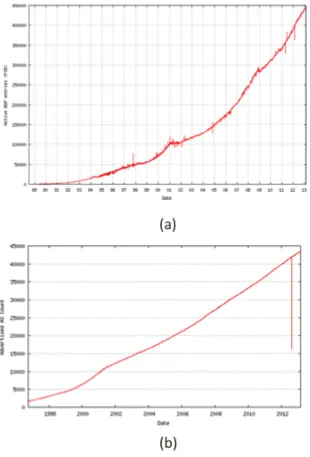
Figure 2.1: a) Number of Active BGP entries and b) Advertised AS assignments over the last decade. (Source: [24]) ... 11
Figure 2.2: Trends in Processor Technology [1] ... 13
Figure 3.1: BGP FSM (Source: Wikipedia [59]) ... 24
Figure 3.3: Task Scheduling in Quagga ... 28
Figure 3.4: Packet Processing in Quagga ... 29
Figure 3.5: Hotspot in BGP Sequential Code ... 32
Figure 3.6: PBTS Master Thread ... 33
Figure 3.7 PBTS Peer Threads ... 34
Figure 3.8: Task Assignment flow in PBTS ... 36
Figure 3.9: Packet flow in PBTS ... 37
Figure 3.10: Eliminating common select logic ... 39
Figure 3.11: Dynamic Task Scheduling ... 41
Figure 3.12: Code for DTS Threads ... 42
Figure 4.1: Network Simulation Setup for generating BGP packet trace. ... 46
Figure 4.2: BGP Simulation Environment ... 49
Figure 4.3: Speedup on different number of cores for PBTS ... 53
Figure 4.4: Time taken in different functions for Sequential Implementation ... 57
Figure 4.5: Speedup achieved for different functions using PBTS ... 58
Figure 4.6: Parallelization overhead in single thread performance of PBTS ... 60
Figure 4.8: Execution Times for 500 consecutive updates on 16 cores ... 64 Figure 4.9: Comparison between execution times for Peer Based Task Scheduling and
Dynamic Task Scheduling Schemes ... 65 Figure 5.1: Execution time with varying L1 and L2 cache sizes for sequential implementation
Chapter 1:
Introduction
Routers are the primary constituent of the Internet backbone and perform most of the intelligent functionality of the network. The functionality of routers can be broadly classified into two categories: Control Plane and Data Plane. While the data plane is concerned with switching and forwarding packets from one interface to another, the control plane has the responsibility of identifying the correct interface to forward those packets on based on their destination address. The control plane achieves this by maintaining a map of the Internet called the routing table, which is pieced together by the connectivity information it receives from its neighbors. Each router runs Routing Protocols to assimilate this information and build a database of the routes available in the Internet, which it in turn advertises to its neighbors to keep each router’s routing table coherent.
Internet size. Physical Internet infrastructure is made up of Autonomous Systems, which is an aggregation of one or more routing prefixes that are maintained by an Internet Service Provider (ISP). Routing protocols that operate within an Autonomous System (AS) and maintain routing information for network prefixes inside a single AS are classified as Intra-domain routing protocols. Most commonly used Intra-Intra-domain routing protocols are Routing Information Protocol (RIP) [27] and Open Shortest Path First (OSPF) [39]. Inter-domain routing protocols are run between different Autonomous systems. Border Gateway Protocol (BGP) [52] is the de facto standard for inter-domain routing protocol that is used on the Internet core. Figure 1.1 represents a very generic view of different routing protocols in a network (‘R’ represents a router and ‘ASn’ represents an Autonomous System).
Figure 1.1: Inter-AS and Intra-AS Routing Protocols
As the routers on the Internet backbone perform a major chunk of data forwarding based on routing decisions made by the BGP protocol, it makes studying BGP all the more important. Over the years, researchers and industry practitioners working in the networking domain have made several efforts to study BGP deployment on the Internet, including traffic trends and BGP packet surges [30, 37], and to improve traffic engineering [21, 50, 51] by configuring the routers efficiently to control and improve routers performance. With the increasing number of BGP routers and Autonomous systems, efforts have also been made to change the protocol itself to make it more scalable, like adding support for confederations [57], route reflectors [4] and flap damping [58]. However, limited effort has been made to optimize the underlying router hardware itself so that it is able to run the BGP protocol more efficiently and scales well with the network size. In our work, we try to fill this gap by doing a detailed study of BGP from the computer architecture perspective with the ultimate goal to contribute towards development of scalable BGP software implementations and efficient network processor hardware.
1.1
Multicore for Routing Protocol Processing
topology and how to reach a particular IP address on the network. Each router can have multiple network interfaces and can potentially receive packets from several neighboring routers simultaneously. For each incoming packet, the router applies different filters based on the configured policies, and subsequently performs a routing table update if the packet passes all the filters. Packets received from different interfaces are independent of each other and can be processed in any order, even in parallel with each other.
1.2
Analyzing BGP from a Computer Architecture
Perspective
While there have been numerous efforts to improve BGP performance from a network protocol perspective, there has not been much work on understanding the BGP performance issues from a computer architecture and system perspective. In this work, we try to address this by undertaking a two-pronged approach of understanding the performance bottlenecks that exist in BGP software implementations, as well as understanding issues in generic CPUs when they run BGP applications.
As a first step towards analyzing BGP, we realized that there are not many tools or simulation software available in academia or industry that enable running BGP on a configurable multicore machine. To enable our work, we have devised a novel methodology to simulate BGP from a computer architecture standpoint. The BGP simulation environment we developed uses a two staged approach, where the first step involves generating BGP packet traces from a realistic network topology and subsequently performing detailed architectural simulations with these packet traces. More details on the simulation environment are discussed in Chapter 3.
execution. The scale and complexity of control plane applications makes porting them to multicore a challenging task. As most routing protocol suites carry over legacy code and only incremental development is done when new features are introduced in the protocol, there is a lot of inertia in changing their software architecture to add support for multithreading. Hence, programmability of routing protocols for multicore processors is another important area where research needs to be done. Coming up with schemes for multithreading the router software which require minimal changes to the software architecture would greatly help in speeding up the process of migrating the routing applications to multicore processors.
1.3
Canonical Multicore Architecture for Routing
Protocols
The data plane of the network processors have used customized hardware implementations to improve their packet processing capability for a long time. Popular network processors like Cisco Quantum Flow and Intel IXP provide customized chip designs which can handle more than 100+ Gb/s packet processing bandwidth inside a single chip which is embedded with several application-specific cores. As an example, the Cisco ASR 1000 [13] consolidates 40 application-specific processing cores on a single piece of silicon to deliver wire-speed data path forwarding features and services. However, for the network control plane, most network processors still rely on general purpose processor architectures. This trend cannot continue in the future, with more and more processing requirements on the control plane. The scale and sheer number of network processors on the Internet backbone justifies having customized control plane hardware, too, which is capable of scaling with the data plane.
throughput. Finally, we propose a canonical multicore architecture suitable for routing protocols that mitigates or eliminates the performance bottlenecks. The changes we propose can be combined with customizations that are required for network control plane applications other than routing protocols, in order to develop efficient Network Processor designs for the future. Further details about the hardware optimizations and canonical architecture are discussed in Chapter 5.
1.4
Contributions of our work
This research makes the following contributions.
• We develop a realistic BGP simulation environment that enables performance analysis at
both the hardware and software architecture levels.
• We give a comprehensive analysis of the generic software architecture for BGP and
propose avenues where parallelism could be extracted by multicore machines [15, 25].
• We propose a task partitioning scheme for BGP called Peer-Based Task Scheduling
(PBTS) [25], show that it achieves significant performance speedup over the sequential implementation, and compare it with another task partitioning scheme developed as a parallel effort in our group [14].
• Based on performance studies, we propose and evaluate architectural mechanisms to improve routing protocol performance.
Chapter 2:
Background and Related Work
2.1
Internet Trends
The number of Internet users has grown more than five times in the last decade (2001-2011) [31], and now spans about one-third of world’s population. The number of connected devices on the Internet is even larger and crossed the number of humans for the first time in 2012 [22]. Interestingly, the amount of data traffic on the Internet will reach more than a Zettabyte/year by 2016, which is of the same order of magnitude as the amount of data transferred by the eyes to the brain of the entire human race in a month [32]. To support these ever growing bandwidth and throughput requirements, the Internet backbone infrastructure has grown considerably.
Providers (ISPs) need to add more Autonomous systems to keep up with this growing trend of connected devices.
2.2
BGP Performance and Moore’s Law
With the increasing BGP processing requirements, one might argue that it matches with the compute power of the latest processors, which is growing at the rate predicted by Moore’s law (i.e. 2x every 1.5-2 years). However, the performance improvements in the latest generation of processors are being made possible by increasing the number of processing cores and not by improving the single-thread performance. In fact, over the last few years, there has been only marginal improvement in the single-thread performance as well as processor frequencies, primarily due to power constraints when running at high frequencies. (See Figure 2.2.) Multicore processors have a much better performance/power ratio, and hence they are able to keep up with the compute power as projected by Moore’s law.
Figure 2.2: Trends in Processor Technology [1]
(Original data collected and plotted by M. Horowitz, F. Labonte, O. Shacham, K. Olukotun, L. Hammond and C. Batten)
2.3
BGP traffic surge and worm attacks
the traffic load was really low at all times, and then there will be bad days when the traffic surges have lasted for few hours with traffic load being many times the average.
There have also been several cases in recent years when dedicated worm attacks have caused a sudden surge in the BGP update traffic, leading to the network routers becoming unresponsive. One instance of that was the slammer worm attack [37], when there was a 24x increase in update traffic between two small edge Autonomous Systems. BGP flap damping [58] is a scheme to prevent such attacks by filtering out changes on a particular network link/route if the changes happen at more than a certain frequency.
Due to this erratic traffic load behavior, it is important to note that when considering the compute power required by BGP, we should take the peak rates into account and not just go by the daily or monthly average rates. With the current compute resources available for BGP packet processing, this may lead to scalability issues for BGP in the near future when there will be cases where the router is not able to handle the peak traffic rates [30].
2.4
Convergence, Stability and Scalability
router, parsing the packet for path vectors, applying filtering policies, performing a routing table lookup for the network prefix and finally updating the corresponding entry in the routing table with this path vector information.
As each BGP router only shares network information with only its peers, which subsequently forward this information to their peers and so on, it might take a long time before a network change propagates through the Internet and every router has the updated network information. The BGP steady state convergence time is measured as the time from a network change to the time when all routes are accepted, entries are made in the routing table and the ingress and egress queues of each router are empty with respect to that change. Higher convergence time means that if the link changes happen very frequently, and the BGP network is not able to propagate them fast enough, the network might not reach a steady state, leading to stability issues and reducing the real time responsiveness of the network.
2.5
Related Work
While there has been a plethora of work [18, 20, 28, 49] to speed up the network data plane using various parallelization techniques, the control plane has lacked such attention. Although the control plane has been evolving in terms of functionality and complexity, routing continues to be the most fundamental task of the control plane. Most research on routing protocols has been done on speeding up BGP, as it is the most important application with high computation requirements, taking over 60% of CPU utilization on routers in certain cases [3]. Most research on BGP in the last decade has been done to improve the protocol specification and configuration to achieve better scalability and reliability, as well as implementing better traffic engineering schemes to improve performance and packet throughput. Only very recently has the focus started shifting towards optimizing the network processor hardware itself to run routing protocols more efficiently. In this section, we discuss some recent efforts that focus on the characterizing and improving network processor hardware performance for networking applications and, more specifically, routing protocols.
2.5.1
Benchmarking Network Processors
CommBench consists of eight different applications, which are classified as either header processing or packet processing applications. NetBench has a different way of classifying applications according to their applicability in the networking stack. They define three types of applications – IP-level, Application level and lower-level micro-workloads. Both Netbench and Commbench mostly focus on the data plane functionality of network processors and do not specifically deal with control plane. Network Processors Benchmark Frame work (NpBench) was the first benchmarking suite that clearly identified control plane as a separate set of applications in addition to the data plane. NpBench includes traffic management, QoS, and security related protocols as part of their control plane benchmark suite. Intel’s benchmarking methodology defines workloads at the hardware level, micro level, function level and system level. It clearly identifies workloads that can be used to characterize different processor and memory performance features for both data and control plane functionality. As we can see, the benchmarking suites have started identifying the control plane applications as a critical component that determines the overall performance of a network processor.
2.5.2
Evaluating BGP performance on different hardware
systems
2400) and a commercial router (Cisco 3620). To evaluate the performance of these systems, they develop a benchmark that exercises different workload scenarios that represent different routing information exchanges that occur in a network.
Table 2.1: BGP Performance without Cross-Traffic (transactions per second) Pentium III Xeon IXP2400 Cisco
Scenario 1 185.2 2105.3 24.1 10.7
Scenario 2 312.5 2247.2 36.4 2492.9
Scenario 3 204.1 2898.6 26.7 10.4
Scenario 4 344.8 1941.7 43.5 2927.5
Scenario 5 1111.1 3389.8 85.7 10.9
Scenario 6 3636.4 10000.0 230.8 3332.3
Scenario 7 116.6 784.3 11.6 10.7
Scenario 8 118.7 673.4 14.9 2445.2
evaluated because of having two cores and support for 2x hyperthreading, giving a total of 4 logical cores. This finding makes a strong case for using multicore machines in the control plane.
2.5.3
Multicore for BGP
Several techniques have been applied to extract parallelism in BGP on multiprocessor systems. Klockar et al. [36] developed a distributed router based on modularized BGP. Zhang et al. [62] propose another BGP model where route computations are done on multiple agents. A major drawback of these multiprocessor implementations is that they do not exploit shared memory (which is commonly available in multicore processors), and hence they incur a lot of communication overhead and provide only limited speedup.
Mittal [48] proposes optimizing the multicore architecture for networking applications. He proposes using hardware offload engines for packet classification and security features which do not come in the actual packet stream flow. He further proposes using a queue at the network interface, and then doing per-processing-element traffic management to utilize the several cores available in a multicore machine. He also proposes modifying the memory architecture to manage separate queues for different data paths.
Chapter 3:
BGP Implementations
BGP is a variant of distance vector routing protocols, which exchanges routing information in the form of path vectors with all its peer routers. Each entry in the routing table consists of destination network, next router and the overall path to reach the destination network. There are several policies that a network operator may choose to configure, based on which networks routes can be added or filtered out. Each BGP router receives update packets with path information from its neighbor, which it adds to its routing table, and then modifies the packet before sending it out to other neighbors. The modified message is essentially appended with its own AS number as the next hop in the path vector. Unlike other network protocols, BGP uses TCP as the underlying transport protocol to ensure reliable communication with its neighbors. This eliminates the need for additional reliability and flow control features in the BGP protocol itself.
the BGP protocol related optimizations and features they implement. For all our BGP analysis, we choose the Quagga BGP implementation, as it is an easily available open source application and that can be compiled and run on Linux/Unix and it implements most of the BGP protocol features. Quagga routing software also implements other popular routing protocols such as RIP and OSPF, and uses some common libraries across the different protocols. Thus some of the improvements that we propose in the Quagga common libraries should also help speed up the other routing protocols. Similarly, although we use Quagga BGP implementation for all our performance analysis, we believe the improvements we propose are applicable to other BGP implementations as well including XORP and Cisco IOS, as they have similar software architectures.
3.1
Quagga BGP
Quagga [33] is a routing protocol suite that is a fork from the GNU Zebra project [34]. It is designed as a collection of separate processes (called daemons) for each routing protocol in the suite. There is a common Zebra daemon, which provides the configuration utility for all protocols in the suite. The following subsections describe further details about the Quagga BGP software architecture and implementation.
3.1.1
BGP State Machine
maintained with each active peer, and packets are exchanged by implementing the standard BGP state machine as specified in the RFC [52]. The state machines are run for each peer and are independent of each other. The state transitions for one peer session do not affect those in other sessions. Figure 3.1 shows the different stages in the BGP FSM.
Figure 3.1: BGP FSM (Source: Wikipedia [59])
3.1.2
Connection Establishment
reaches a steady state where it only gets update messages for any network changes that are happening.
3.1.3
Routing and Lookup Tables
The routers exchange update messages with path vectors to share the routing information of different network addresses stored in their routing tables. The path vectors are called Network Layer Reachability Information (NLRI), and a router can receive and advertise multiple NLRI’s simultaneously. On receiving an NLRI message, the router makes appropriate entries in the routing tables and advertises routes to its peers based on the policies it exchanged with the peer during the initialization phase.
There are a few different conceptual routing/lookup tables maintained inside each router. Each routing table entry consists of a destination network prefix, a path vector (a list of AS numbers), and the next hop AS information.
• Local Routing Information Base (RIB) – This is the master routing table that is
maintained by the BGP router. It stores NLRI’s for all known network prefixes.
• Adjacent Routing Information base – This is further broken down into Adj-RIB-In,
• Forwarding Information Base - Holds the best routes that should be used for reaching
a particular network prefix. If a new entry is added in RIB that has a better route to the same prefix, then FIB is updated appropriately. This table is common across the Quagga routing suite. It is updated by other routing protocols, as well, and is also used by the data plane for actual data forwarding.
When we mention conceptual lookup tables, it means that, in Quagga, there is only one physical entry maintained for each NLRI. The Local and ADJ RIB’s store NLRI pointers that point to the same physical entry in the NLRI database. Figure 3.2 depicts the Quagga software architecture and shows the critical data structures.
3.1.4
TCP communication and Stream Processing
Streams are byte buffers that are maintained for each peer session and hold the incoming and outgoing packets. In the BGP implementation, two streams buffers are maintained for each peer connection, one for the incoming packets from a peer session and the other for outgoing packets. Each buffer is sized to hold one maximum-sized BGP packet. When a new packet arrives from a neighbor on the corresponding TCP socket, it is read into the incoming stream buffer using TCP read. Subsequently, all packet parsing functionality is performed by reading data from this buffer. Similarly, any outgoing BGP packet is first composed in the outgoing stream buffer by appending different header and payload fields before it is pushed out using TCP write. Quagga routing suite provides a separate stream library API to handle these byte buffers, which are used by all the protocols in the routing suite. As we will see later, we propose some improvements to the stream buffering and processing functionality, which is done by making changes to the stream API.
3.1.5
Task Scheduling
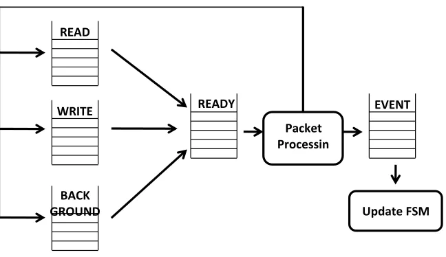
The implementation maintains five task queues: event, ready, read, write and background. Tasks to be performed by BGP router are segregated into these queues. Read queue holds tasks scheduled to read data from the incoming TCP buffer. When there is data to be read, the task is moved from the read queue to the ready queue. Similar is the case for write queue.
Figure 3.3: Task Scheduling in Quagga
All BGP timers are held in the background queue and moved to ready queue when they expire. Event queue holds all the events generated by the state machine. Tasks are picked up from the event and ready queues and are executed one at a time. Event queue has priority over the ready queue. Figure 3.3 shows the flow of tasks between different queues in Quagga.
WRITE
BACK GROUND
READY EVENT
Packet Processin
g
3.1.6
Packet Flow in Quagga BGP
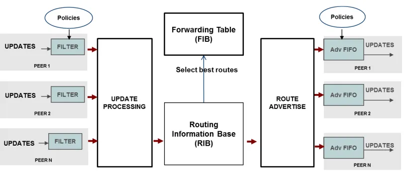
After booting and completing the connection establishment with each of the configured peers (as described in section 3.1.3), the BGP router receives and sends route updates and withdraw messages. On receiving a route update, it is first moved to the Adj-in-RIB, from where each packet is filtered based on different BGP policies that are configured by the service provider. A packet that passes the filters goes through the processing phase, where its network prefix is looked up in the loc-RIB, and the NLRI entries are updated. Subsequently, the route advertisement functionality is performed, which determines which NLRI updates or withdraws need to be sent out to different peers. These packets are moved to the Adj-out-RIB. When the route advertisement timer for a particular peer connection expires, the corresponding ADJ-out-RIB is looked up and update/withdraw packets are composed and sent out. Figure 3.4 shows the overall packet flow through the software pipeline.
3.2
Peer Based Task Scheduling
Once the router has booted and established TCP connections with each neighboring node, each neighbor transfers a huge number of route updates, transferring all the relevant routing table information. On a real network, this would mean a router receiving updates corresponding to almost all the AS prefixes on the internet, which is around 10 MB of TCP data received within a few seconds at the router’s ingress queue. Similarly, during packet surges, there are many update packets queued up at the incoming interface.
An interesting behavior of the BGP protocol is that data from all incoming peers is independent of each other. A separate TCP connection is maintained for each peer and the state transitions for one connection are independent from another. The first BGP parallelization scheme that we develop exploits this peer connection independence property to divide the work done by the router into multiple threads. As each thread operates on incoming data from a particular peer, we call this scheme Peer Based Task Scheduling (PBTS) [25].
3.2.1
Parallelization Approach
processing it is classified as a _READ task, a state machine transition is identified as a _EVENT task, and all timers including housekeeping, route advertisements, and so forth, are identified as _TIMER tasks. Each task has an associated validating condition, which when true enables the task to be marked as _READY for execution. As an example, the validating condition for any timer is when the current wall time is greater than the timer expiry time. The validating condition for a _READ task is when the data becomes available at the network interface.
Figure 3.5: Hotspot in BGP Sequential Code
run on their dedicated cores. Figure 3.6 shows the code executed by the master thread and 3.7 shows the code executed by the peer threads.
Figure 3.7 PBTS Peer Threads
The thread definitions for PBTS implementation are as follows:
• Master-Thread - Common among all peers and handles
o Clearing routing tables,
o Checking socket buffers for new data and notifying peer threads, as well as maintaining file descriptor sets.
o Keep a TCP socket open in passive mode and listen for any new BGP connection requests. Whenever the router receives a connection request from a peer router, the master thread spawns a new peer thread.
• Peer-Thread - This thread maintains a TCP connection with the peer and runs its
Figure 3.8: Task Assignment flow in PBTS
3.2.2
Synchronization
Routing Table Locks
Routing tables in Quagga are maintained as trees, with each prefix represented as a node in the tree. Two lock variables are defined per routing node: one for traversal when a thread just wants to read the tree without modifying any node, and the other for node modification when a new node needs to be added to the tree or contents of a node need to be modified. These two node specific lock variables enable maintaining a fine grain locking in the routing tables, allowing multiple threads to modify the tree as long as they are accessing different locations in the tree and do not interfere with each other.
File Descriptor Set lock
In order to read data from the underlying TCP buffer, independent sockets are maintained for each peering router. Select() function is used to wait for new data on the TCP buffer, and common read and write file descriptor sets are maintained to track new incoming packets. As the file descriptor sets are shared among different peers, the use of select logic necessitates modification of FD sets serially, to ensure that when select logic is called, no other threads is accessing the FD set. Hence a lock variable has to be acquired before accessing the FD set to know if there is new data for the particular peer on the TCP buffer.
Figure 3.10: Eliminating common select logic
3.2.3
PBTS performance considerations
However, a disadvantage of this scheme arises in cases when all the peer nodes do not communicate the same number of packets, and the incoming data flow is skewed towards only a few threads instead of being evenly distributed across all threads in the multicore processor. In these cases, the hardware is not efficiently utilized for packet processing. This disadvantage is mitigated by an alternate task scheduling mechanism called Dynamic Task Scheduling (DTS), which we discuss in the next section (3.3).
3.3
Dynamic Task Scheduling (DTS)
While the PBTS scheme spawns threads on each new connection request, DTS follows a different approach and spawns a fixed number of threads when the router boots up. The number of threads started is proportional to the number of cores on the multicore machine. This approach allows all the CPU cores to be utilized evenly for packet processing. In DTS, the master thread does the job of maintaining the _READ and _TIMER and _READY task queues for all peers. The actual functionality of executing the _READY tasks is moved to the other threads. Each thread has a separate _READY queue from where it picks up valid tasks and executes them. The master thread scans for new packets on the TCP buffer and performs timer management for all peer connections. When any _READ or _TIMER task becomes ready, it copies the ready task to _READY queue of a thread in a round robin fashion. This ensures load balancing on each thread.
operating on packets for the same peer, another level of synchronization needs to be maintained in order to keep the data coherent for a particular peer. As mentioned earlier, two streams are maintained for each peer to store the incoming and outgoing packets. When multiple threads operate on packets from the same peer, these streams could potentially get corrupted and hence need to be accessed in a critical section. A peer lock is maintained inside the peer structure, which limits the peer data structures to be modified by a single thread at a time. Figure 3.11 shows packet flow in DTS and 3.12 shows the code being executed in the main loop of DTS. More details on several optimizations as well as detailed performance results for DTS are part of a separate work [14].
Chapter 4:
Performance Analysis
4.1
Simulation Environment
BGP workloads, based on a two-step approach of generating functional traces and then using trace driven methodology to run detailed multicore simulations.
1. Generate a BGP packet trace at every autonomous system by running high-level network simulations with a sufficiently large number of nodes and a representative Internet topology. These simulations are functionally accurate but do not model any performance related issues.
2. Choose an arbitrary system from the above network simulation and run detailed architectural simulations (with appropriate CPU and Memory modeling) driven by packets from the trace generated in step 1.
Section 4.1.1 elaborates the packet trace generation methodology using network simulator, and section 4.1.2 details the GEMS [45] and Simics [44] based evaluation environment that we use for detailed multicore architecture simulations and analysis.
4.1.1
Generating BGP Traces
Network Topology
convenient GUI-based interface for configuration. We generate a network with each node connected to 10-15 neighboring nodes.
Network Simulations
Once we have a representative network topology, the next step is to generate functionally accurate network simulations. We use Network Simulator (NS2) [54] for simulating the BGP network. NS2 requires a script that defines all the components in the network along with the connectivity information. It uses BGP++ as an agent for BGP simulations.
• BGP agent – NS2 does not have a built-in protocol simulator for BGP. BGP++ [17]is
used as an NS2 agent that performs BGP simulation based on the given configuration. It is based on the same code used in Quagga routing software with modifications done in order to use the TCP/IP stack of NS2 for packet transmission and reception. BGP++ takes a configuration file as input, which contains the peer information and the prefixes to be advertised by a particular node, and generates a log for all the state machine and path information. It also generates a dump (in MRT format [6]) for all the packets exchanged. This tool was used to perform network simulation for several BGP nodes and generate corresponding packet dump files.
• BGP++ Configurator - BGP++ configurator [16] takes the network topology as an
Figure 4.1 shows steps involved in generating BGP packet trace using network simulation.
Figure 4.1: Network Simulation Setup for generating BGP packet trace.
Topology
BGP++ Conf
4.1.2
Multicore Simulation Environment
Once BGP traces are generated, we choose a center node from the network that has 12 peer connections, and use the MRT-based packet trace collected at the ingress of this node. This packet trace file will be used to feed packets into the multicore model of the BGP processor. A Simics-based simulation environment is used to run the multicore network simulations. We initiate two virtual hardware systems in Simics, and connect them using a single Ethernet link. The first virtual machine runs the sequential or parallel version of the Quagga BGP daemon. The second virtual machine runs the BGP Simulation Client. This simulation client is a program we developed that reads BGP packets from the trace file and feeds it to the Quagga BGP daemon.
BGP Simulation Client
with BGP Daemon. We have designed three different variants for this simulation client to run different types of experiments.
• The first version reads the packets from the packet trace MRT file in-order and sends
them to the BGP daemon. This leads to a random order of packet dispatch on the different peer connections. In this case the BGP daemon receives packets in exactly the same order as what was generated using the network simulator.
• Second version of the client does a round robin read of the packets, picking one
packet for each peer connection and then moving on to the next connection. This scheme allows a balanced packet load for each thread in the parallel BGP implementation. We further configure this version to allow sending N packets to each peer, instead of one, before moving onto the next connection.
• The third version of the simulation client is multi-threaded, where we spawn one
Figure 4.2: BGP Simulation Environment
BGP Daemon
4.2
BGP Performance Analysis
In this section, we provide a detailed performance analysis of the sequential and multithreaded BGP implementations. We evaluate the performance under different multicore configurations and BGP network scenarios. All the simulations are performed on a system with MOSI coherence protocol and a private L2 cache. Processing times are measured in terms of Ruby cycles (Ruby is the memory and interconnect component of GEMS and a Ruby cycle corresponds to one cycle of the cache controller). Table 4.1 shows the generic configuration of the multicore processor used for all simulations unless specified otherwise. We use a generic compute server architecture for the processor model, since BGP routers still mostly run on general purpose architectures with little customization for control plane processing.
Table 4.1: Multicore Parameters
Processor Ultrasparc III running Solaris 10
L1 Cache Split I&D, 64 KB 4-way set associative, 1 cycle access latency, 64-byte line
L2 Cache Private L2 cache per processor, (1 MB), 6 cycle access latency, 64-byte line
Interconnect Hierarchical switch, 13 cycle link latency, 4 virtual channels, 4 buffers per virtual channel
Coherence MOSI Protocol
4.2.1
Code modifications for Performance Analysis
In order to do detailed performance analysis and understand the performance impact of our parallel implementation under different scenarios, we make the following changes in the sequential and parallel implementations.
• Disable Timers – There are several timers that are run in the BGP protocol, such as
KeepAlive timer that is triggered when there has been no communication with a peer for some amount of time. Since these timers are not performance critical and do not require much processing, we disable all such timers when running the performance simulations.
• Feeding packets as fast as possible – The primary metric to determine the
effectiveness of the parallel BGP implementations is the throughput when processing route updates. Hence, we feed route update messages to the BGP daemon as fast as possible. To enable this, we ignore the timestamp values when reading packets from the MRT packet trace in the BGP simulation client, and allow the client to send the packets as fast as it can.
• Disabling Route Advertisements - Route advertisements to the peers happen
critical path which is the time from receiving an update at the ingress port of the router to the time is accesses or modifies the routing table.
• Trigger detailed architecture analysis after connection establishment – The
connection establishment phase completes when the BGP simulation client has initiated connection requests for all the peering connections and the BGP daemon has responded with appropriate response messages. The detailed architectural simulator and performance stats collection is triggered only after all BGP connection establishment messages are complete.
4.2.2
Parallel Application Speedup
4.2.3
Profiling Sequential and Parallel Implementations
To analyze performance, we divide the basic functionality of a BGP router into the following:
• Connection Establishment: This happens during the initialization phase when a router
establishes connection with its peers. Since this happens only once when the router boots up, we don’t analyze the time taken by the router in the initialization phase.
• TCP Polling: Time it takes for the router to probe the underlying TCP Buffer for new
packets.
• Task Queue Handling: This involves moving tasks from Read and Write queue to ready
queues when the router receive update messages and when it needs to advertise routers to peers.
• Packet Processing: This is the main part that involves the entire packet processing
functionality of the router. This could be further divided into six functions:
1, 2) Header Read and Header Parse for processing the header of the BGP packet. The read part involves reading the packet from TCP buffer.
3, 4) Payload Read and Payload Parse involve reading and parsing the variable length payload of the packet. This part also includes applying different BGP policies to the packet before any changes are made to the routing table.
6) Housekeeping covers other miscellaneous functionality including checking the peer status and validity of the packet before starting to process it.
Packet processing for BGP involves processing incoming packets and generating BGP route advertisement messages for peer routers. Since the route advertisements are done periodically when a timer expires, they do not form the critical path of packet processing. Hence, we provide a detailed analysis of only the incoming packet processing part. Figure 4.4 shows the time taken by different parts of the packet processing functionality for the sequential BGP implementation. Approximately 70% of the time is spent on the packet parsing and routing table updates. The TCP buffers reads (Header and Packet read) add up to 26% of the total time taken. Housekeeping overhead for the packet is almost negligible at 3%.
Figure 4.4: Time taken in different functions for Sequential Implementation
Figure 4.5: Speedup achieved for different functions using PBTS
Table 4.2: Average number of ruby cycles and speedup achieved per packet for different functions
Function Sequential PBTS PBTS Speedup
Table Update 272.8 26.2 10.4
Packet Parse 1123.1 139.7 8.0
Header Parse 58.9 5.1 11.6
Packet Read 1087.2 135.3 8.0
Header Read 4176.6 397.7 10.5
House-keeping 1857.0 198.5 9.4
It is important to note that PBTS is designed to speed up the update processing in BGP, which is in the critical path towards improving packet throughput and convergence time. The update processing functionality is sped up by 9.5 times in PBTS. However, this speedup is not reflected in the overall execution cycles for PBTS, mainly due to the following reasons:
1. The Quagga BGP code collects stats and timestamps for each packet, which internally does a system call, causing the application thread to context switch and consuming significant number of CPU cycles.
times for each thread don’t match, causing a higher total run time. This is a simulation artifact and has nothing to do with any threading overhead in PBTS.
Figure 4.6 shows the parallelization overhead when single thread performance is considered. The overhead in header and packet read functions is due to accessing the TCP buffer. In the parsing and table update functions, overhead is due to the lock instructions.
4.2.4
Traffic Behavior
PBTS performance depends on the activity factor from different peers. In this section, we provide an analysis of PBTS performance under different peer burstiness levels. What we mean by level of burstiness is the number of update messages received from a particular peer before the next set of messages is received from another peer. It can also be defined as the number of peers that are sending messages simultaneously. Higher burstiness level means, the higher the load on a particular core. Table 4.3 shows the different traffic mixes generated by the BGP simulation client.
Table 4.3 Different packet mixes generated by the BGP simulation client
Mix Description
Best All peers sending packets, 1 packet at a time.
Mix1 All peers sending packets, in a realistic order (generate from Network Simulation). Also called normal mix.
Figure 4.7 shows the performance of PBTS under these different traffic mixes. As can be seen, the performance of PBTS degrades from best-case scenario when there is perfect load balance, to worst-case scenario when there is only one thread active at a time, thereby underutilizing the multicore system. As observed through our 1000 node BGP network simulations using NS2, the incoming packet traffic is a good mix of packets from different peers. Therefore, the worst-case scenario would be rarely observed and the performance does not need to be optimized for different burstiness levels. The speedup that we calculate for the parallel application is with Mix1, which is a realistic packet trace at an NS2 node.
4.2.5
Larger Traces and Routing Tables
Figure 4.8: Execution Times for 500 consecutive updates on 16 cores
4.2.6
PBTS vs. DTS
overheads for maintaining thread based streams and dedicated task queues per thread, which result in execution overhead. Due to the pros and cons of each scheme, we see that the performance numbers of PBTS and DTS only differ marginally on 8 or 16 cores.
Chapter 5:
Multicore Architecture for BGP
Section 5.1 evaluates impact of different memory configurations on sequential and parallel BGP performance. We propose adding a new feature in the architecture for improving the header and packet parsing functionality, which was identified as the biggest hotspot during the performance analysis in the previous chapter. The implementation details and evaluation of this new feature that we call ‘Steam Hardware Assist’ is discussed in Section 5.2. Section 5.3 provides a literature survey of several network subsystem and TCP optimization techniques, which can potentially speed up the header and packet read functions that form the second biggest hotspot in PBTS.
5.1
Memory Analysis
DTS. As PBTS and DTS are running on 16 cores, the total L2 size thus amounts to 256K*16 = 4MB. The parallel implementations have a little larger working set, as expected, because of the additional data structures that were introduced in the PBTS and DTS for achieving performance speedup.
5.2
Hardware Assist for Fast Stream Access
Packet and Header parsing forms a major part of the BGP execution time, taking as much as 47% of the execution time of the PBTS implementation. Inside packet parsing, most of the cycles are spent in reading data from the stream and processing it. In order to remove this bottleneck, we perform a limit study and propose a mechanism to speedup stream accesses called Stream Hardware Assist (SHA).
During the Header/Packet read and parse functions, the streams are written to and read from only once. In a processor with conventional memory hierarchy, when a thread tries to access stream data, it would cause a cache miss and request data from the memory. Subsequently, the data would be used once and evicted, leading to suboptimal performance of the L1 and L2 caches. On the other hand, if a dedicated hardware memory (working in parallel to an L1 cache) is assigned to each thread for exclusively storing the streams, the total number of stream access cycles can be significantly reduced. The latter scheme is the rationale behind SHA.
prefetching, data is usually accessed from memory, whereas in case of stream hardware, the data can be directly accessed from the network interface card as discussed in the next subsection.
In the BGP implementations, the data structure used for storing ingress and egress packets are 1KB in size (to hold the maximum BGP packet size). Hence, the size for the dedicated stream buffer per thread should be 4KB. For such a small memory, we can safely assume single cycle access latency. We analyze the impact of stream buffers on PBTS and DTS performance by assigning single cycle latency for all stream accesses that happen from the packet parsing function. The simulations are run with normal latency for all other memory access instructions.
We analyze the impact of stream buffers on PBTS and DTS performance by assigning single cycle latency for all stream accesses that happen from the packet parsing function. The simulations are run with normal latency for all other memory access instructions. Stream accesses are 37.2% of the total packet parsing instructions and 17.4% of the overall instructions in the sequential implementation. (Packet parsing is 47% of the overall execution cycles.) Thus, speeding up stream access has a significant impact on overall execution time, as can be seen in table 5.1, which shows the speedup achieved by using hardware assist for fast stream accesses on PBTS and DTS. Stream hardware assist gives up to 5.85% speedup on PBTS and 6.67% on DTS.
To enable stream hardware assists in the real processors, support is required at the compiler and instruction set levels. The stream access instructions in the stream library need to be replaced with special instructions for accesses data from a different memory. As the stream accesses are made from a single stream library in the Quagga protocol suite, this requires minimal effort from the software perspective.
Table 5.1: Potential speedups using Stream Hardware Assist Function Speedup (PBTS) Speedup (DTS)
Stream accesses 31% 38.5%
Packet parsing 13% 14.21%
Hardware modeling of this technique involves two steps:
• Adding a cache-like data structure close to the core in parallel to the L1 cache, to
which all the accesses to stream addresses are redirected.
• Modifying the TCP/IP stack to redirect all the incoming packets to the stream buffer.
This can be achieved either by a) modifying the TCP functionality to copy data from the TCP buffer to Stream buffer when a read function is called from the BGP application, or b) Implementing a NIC with the capability to DMA the data directly into the stream buffers (discussed in the next section). The latter approach has less overhead and better performance compared to the former. Further discussion on placing the Stream Hardware Assist in hardware is done in Section 5.4.
5.3
Improving TCP Read performance
Almost 26% of execution cycles in PBTS and DTS are spent in TCP read that copies the data from TCP buffer to the stream data structure of each thread. The data is first copied from the network interface card to the TCP buffer and then from the TCP buffer to the input stream data structure. (To clarify, the stream data structure that we refer here pertains to the buffer that is allocated by the BGP software to store packets, and is different from the stream hardware assist that we proposed in the last section.). In this section, we dive deeper into this problem and discuss mechanisms to improve the header and packet read performance.
5.3.1
TCP Bottlenecks in Parallel BGP Implementation
The TCP bottlenecks in the PBTS scheme are twofold,
• The first issue is the high latency for transferring a packet from the NIC interface to
the application buffer. The high latency comes from the fact that there are two sets of memory copies happening for the same data before it is used by the application. When an execution thread completes processing one packet, it wastes CPU cycles waiting for another packet to arrive, thus causing inefficiency.
• The second issue arises because only a single thread can access the TCP/IP stack at a
peers, so they can have incoming data from multiple interfaces at the same time requiring the TCP stack to be more efficient to handle multiple threads.
There has been a lot of research on optimizing TCP performance at the system level. Most research can be broadly classified in the following categories:
1) Reducing or completely eliminating the memory copy operations that cause high latency in the TCP stack. This also includes work on forwarding the data directly from the NIC to the application buffers.
2) Optimizing the TCP stack for multithreaded applications thereby removing any serialization when each OS thread/process is communicating with a different socket. 3) Alternate NIC implementations that address both of the above issues but with a
different hardware implementation or moving the packet handling part of the NIC to software.
The following subsections discuss contemporary research work in each of these three areas and discuss how parallel BGP implementations can benefit from them to remove TCP related performance bottlenecks and improve overall performance.
5.3.2
Reducing TCP Read latency
application generates the data, and this necessitates a need for introducing an intermediate buffer for rate matching. On the receiving side, two levels of copy allow OS to place the incoming data at a virtual address that is specified by the application. This situation has motivated development of techniques to reduce or eliminate data copying, making the TCP stack more efficient. Much work has been done to eliminate the double copies in the TCP/IP stack of different operating systems including Solaris [11] and Linux [56], as well as evaluation on OpenBSD [55]. To avoid the requirement of additional buffering in the kernel space, most zero-copy schemes involve complex interactions between the networking hardware, operating system and application software, including designing dedicated OS buffering schemes and application programming interfaces.
Chase et al. [10] do a detailed investigation of various schemes available in literature that improve TCP latency on sending and receiving hosts. They provide quantitative analysis of the potential improvements with these schemes on an experimental network setup. In addition to zero-copy, checksum offloading is another popular technique that helps reduce the TCP send and receive latencies. Since checksum is calculated on the entire TCP packet, including the header and payload, to detect packet corruption and is calculated on both sending and receiving sides. It requires all packet data to be loaded through the memory hierarchy to perform the checksum add operations. This introduces a high latency before the memory copy operation. Combining the checksum operation with another operation that touches all bytes of the packet can eliminate this cost. Since the packet passes through the DMA interface when being transferred between the NIC and host memory, checksum computation can be added to the DMA interface with minimal extra cost.
5.3.3
TCP for Multithreaded Applications
Another TCP bottleneck that we encounter in PBTS is when multiple threads try to perform TCP reads at the same time. This issue arises because there is only a single TCP stack that each thread tries to access, and hence it becomes a serialization point. As shown in Figure 4.5, processor cycles spent performing the header read function increased by 90% in PBTS compared to the sequential implementation. Similarly, cycles spent in packet read function increased by almost 45%. This poses a big scalability issue when the number of threads is increased. There has been some work done on improving the performance of TCP for multi-threaded applications by instantiating multiple TCP stacks and adding packet classification features in the NIC. These schemes tend to give performance improvements when each TCP connection is assigned to only one thread. Since PBTS complies with this requirement, it can potentially benefit from these TCP optimizations.

![Figure 2.2: Trends in Processor Technology [1]](https://thumb-us.123doks.com/thumbv2/123dok_us/1774596.1228545/27.612.102.531.87.355/figure-trends-in-processor-technology.webp)

![Figure 3.1: BGP FSM (Source: Wikipedia [59])](https://thumb-us.123doks.com/thumbv2/123dok_us/1774596.1228545/38.612.90.525.72.342/figure-bgp-fsm-source-wikipedia.webp)