ABSTRACT
HAMPAPUR VENKATNARAYAN, RAGHAV. Using Ambient Signal Modalities for Ubiquitous Sensing. (Under the direction of Dr. Muhammad Shahzad.)
Fast and accurate perception of human presence and interaction is a challenging problem for realizing smart environments, especially at the network edge. While current approaches largely use cameras and depth sensors for sensing human movements, they cannot be deployed in all environments due to a variety of reasons such as limited field-of-view, access restrictions, lighting requirements, and privacy concerns, which limit their ubiquity. However, given the ubiquitous presence of WiFi and lighting fixtures in today’s buildings, it is possible to ameliorate the problems of camera-based approaches by switching to widely available signals such as ambient WiFi or ambient light. This is because these pervasive signals are also affected by human movements, which can be exploited to achieve seamless, low-cost human sensing applications at the network edge.
Therefore, in this work, we study the use of ambient signals for realizing ubiquitous sensing applications with commodity devices. Specifically, we explore four novel and challenging problems of ubiquitous sensing, using only ambient WiFi and light signals. The first three problems involve ubiquitous sensing with ambient WiFi signals that are unresolved in the literature: (i) accurately measuring distance moved by humans (or robots) in indoor environments, (ii) accurately tracking indoor location of multiple human targets, and (iii) accurately recognizing simultaneous gestures of multiple persons. Meanwhile, the fourth problem explores the use of ambient light signals for the first time, to perform human gesture recognition.
The first problem of accurately measuring the distance traversed by a subject,i.e.odometry, is of fundamental importance in many applications such as position tracking for virtual reality, indoor navigation, and robot route guidance. While theoretically, odometry can be performed with accelerometers, practically, it is well-known that distances measured using accelerometers suffer from large drift errors. To solve this problem, we propose WIO, a WiFi-assisted Inertial Odometry technique that uses ambient WiFi signals as an auxiliary source of information to correct drift errors. The key idea behind WIO is that, because multiple copies of a transmitted WiFi signal arrive along different paths to a WiFi receiver, WIO can first isolate one reflection path and then measure the change in its path length during subject motion to derive the traversed distance. To demonstrate the idea, we implement WIO using commodity devices, and evaluate it extensively in a variety of complex indoor scenarios on both human and robotic subjects. Our results demonstrate an average error of just 6.28% in estimating the distances traversed by the subjects.
polarization diversity of WiFi signals. The key insight of WiPolar is that the human targets in a track-ing environment possess varied horizontal and vertical radar cross-sections due to their physical dimensions and reflection characteristics. This consequently allows for more accurate resolution of multiple human reflections in the polarization domain. Thus, WiPolar introduces polarization diversity in the transmitted WiFi signal to first jointly measure a polarization parameter of multiple human reflection paths along with their Angle-of-Arrival, Time-of-Flight and Doppler-Frequency Shift and then continuously derive their locations. To demonstrate this idea, we implement WiPolar using commodity WiFi devices and evaluate it extensively in multiple environments. Our results show that WiPolar achieves a median tracking error of just 56cm for up to five humans, with over 73% reduction in the median tracking error due to the use of polarization-diversity.
The third problem of multiple-person gesture recognition has applications in Virtual Reality, such as group interaction. Similar to human tracking, existing ambient WiFi signal based gesture recognition approaches are also limited to recognizing gestures of only a single human target. To address this limitation, we propose WiMU, a WiFi based Multi-User gesture recognition system. The key idea behind WiMU is that it develops theoretical models of multiple-person limb movements. This allows it to identify features from patterns of multiple-user reflections in the received WiFi signal and then recognize them using machine learning techniques. To illustrate our idea, we implement and extensively evaluate WiMU with commodity WiFi devices. Our results show that WiMU recognizes 2, 3, 4, 5, and 6 simultaneously performed gestures with accuracies of 95.0%, 94.6%, 93.6%, 92.6%, and 90.9%, respectively.
© Copyright 2019 by Raghav Hampapur Venkatnarayan
Using Ambient Signal Modalities for Ubiquitous Sensing
by
Raghav Hampapur Venkatnarayan
A dissertation submitted to the Graduate Faculty of North Carolina State University
in partial fulfillment of the requirements for the Degree of
Doctor of Philosophy
Computer Science
Raleigh, North Carolina
2019
APPROVED BY:
Dr. Ismail Guvenc Dr. Harry Perros
Dr. Khaled Harfoush Dr. Muhammad Shahzad
DEDICATION
BIOGRAPHY
Raghav H. Venkatnarayan was born in Mudis, Tamil Nadu, India. He received his primary and secondary education in Mysore, Karnataka, India and went on to receive his Bachelor of Engineering degree in Computer Science and Engineering from Visvesvaraya Technological University, Belgaum, India in 2012. Raghav also holds a Master of Technology degree from the International Institute of Information Technology, Hyderabad, India in Computer Science and Engineering. His research interests include design, modeling, and implementation of data driven applications in human sensing, wireless communications and mobile computing.
ACKNOWLEDGEMENTS
I would like to thank Dr.Shahzad for his unflagging encouragement, support and faith in my work. He has been a pillar of strength throughout the time it took me to complete this research and write the dissertation. I am very grateful to him for persevering with me through challenging times, and for championing my work that has made a significant impact on my research career.
The members of my dissertation committee, Dr.Harry Perros, Dr.Khaled Harfoush, and Dr.Ismail Guvenc have generously given their time and expertise to better this work. I thank them for their inputs and kind support.
I am grateful to many colleagues who shared their memories and experiences, especially my former lab member, Aditya Virmani who generously shared his background knowledge that helped expand my own work.
Many thanks to my wife, Surabhi Shouche who has stood by me through all my travails and my absences. She has supported me throughout most of my graduate study here at NC-State, helped discuss ideas and also prevented several wrong turns. I also want to thank my immediate family, Rashmi and Kirthi Narasimhan, Venkatnarayan Hampapur, Manisha Narayan, Rohit and Thara and Nadipuram Narasimhan for their constant support, inspiration and encouragement.
I must also acknowledge all the many friends, colleagues, graduate students, volunteers, admin-istrative staff and librarians who assisted, participated and supported my research efforts over the past four years.
TABLE OF CONTENTS
LIST OF TABLES . . . .viii
LIST OF FIGURES. . . ix
Chapter 1 Introduction. . . 1
1.1 Motivation . . . 1
1.2 Key Contributions . . . 3
1.3 Thesis Outline and Organization . . . 4
Chapter 2 Enhancing Indoor Inertial Odometry with WiFi . . . 6
2.1 Introduction . . . 6
2.1.1 Motivation: . . . 6
2.1.2 Limitations of Prior Art: . . . 7
2.1.3 Problem Statement: . . . 9
2.1.4 Proposed Approach: . . . 9
2.2 Related Work . . . 10
2.2.1 WiFi Assisted Inertial Odometry . . . 10
2.2.2 WiFi-based Localization . . . 12
2.2.3 Other Auxiliary Information Sources . . . 12
2.3 Distance Estimation Using WiFi . . . 13
2.3.1 Approximation∆θk≈0 . . . 14
2.3.2 Estimating∆lk . . . 15
2.3.3 Estimatingθk{t}. . . 18
2.3.4 Eliminating Disturbances due to Humans/Mobile Objects . . . 19
2.3.5 Summary of Steps . . . 21
2.4 Augmenting IMU with WiFi . . . 22
2.4.1 Distance Estimation Using IMU . . . 22
2.4.2 Drift Correction for Accurate Distance Estimation . . . 22
2.5 Implementation . . . 24
2.5.1 Collecting CSI Measurements . . . 25
2.5.2 Collecting IMU Measurements . . . 25
2.5.3 Feasibility of Implementation on Smart Phones . . . 26
2.6 Evaluation . . . 26
2.6.1 Evaluation on Human Subjects . . . 26
2.6.2 Evaluation using a Drone . . . 38
2.6.3 Exploring the Use of WIO in Localization . . . 41
2.7 Conclusion . . . 42
Chapter 3 Leveraging Polarization of WiFi Signals to Simultaneously Track Multiple Peo-ple . . . 43
3.1 Introduction . . . 43
3.2 Related Work . . . 47
3.3 Estimating Path Parameters . . . 48
3.3.1 CFR Model . . . 48
3.3.2 Parameter Estimation . . . 49
3.5 Localization and Tracking . . . 55
3.6 Preconditioning the CFR . . . 59
3.7 Performance Evaluation . . . 60
3.7.1 Evaluation Setup . . . 60
3.7.2 Tracking Performance . . . 62
3.8 Conclusion . . . 66
Chapter 4 Multi-User Gesture Recognition Using WiFi . . . 67
4.1 Introduction . . . 67
4.1.1 Motivation: . . . 67
4.1.2 Problem Statement: . . . 68
4.1.3 Proposed Approach: . . . 68
4.2 Related Work . . . 69
4.2.1 CD-based Human Sensing Systems . . . 70
4.2.2 SH-based Human Sensing Systems . . . 70
4.3 Multi-User Movement Model . . . 71
4.3.1 CFR Power Model . . . 71
4.3.2 Insights . . . 72
4.4 WiMU – Overview . . . 73
4.5 Frequency Extraction . . . 75
4.5.1 Primary/Secondary Frequency Separation . . . 76
4.5.2 Coarse Frequency-Models of Gestures . . . 77
4.5.3 Setting the Baseline Threshold . . . 77
4.6 Gesture Segmentation . . . 78
4.6.1 Detecting a Set of Simultaneous Gestures . . . 78
4.6.2 Detecting the Gesture Start & End Times . . . 78
4.6.3 Pairing the Gesture Start & End Times . . . 80
4.7 Gesture Combination Selection . . . 81
4.8 Virtual Sample Generation . . . 81
4.8.1 Matching Sample Durations . . . 81
4.8.2 Generating a Virtual Sample . . . 82
4.9 Gesture Recognition . . . 82
4.10 Implementation & Evaluation . . . 83
4.10.1 Data Collection . . . 84
4.10.2 Comparison of Real vs. Virtual Samples . . . 85
4.10.3 Gesture Segmentation Accuracy . . . 85
4.10.4 Combination Selection Performance . . . 86
4.10.5 Gesture Recognition Accuracy . . . 87
4.10.6 Comparison with Prior Art . . . 88
4.10.7 Impact of Height and Weight . . . 88
4.10.8 Impact of Distance Between Users . . . 89
4.10.9 Impact of Environmental Changes . . . 90
4.10.10 Processing Latency . . . 91
4.11 Conclusion . . . 91
Chapter 5 Gesture Recognition Using Ambient Light. . . 92
5.1 Introduction . . . 92
5.1.2 Problem Statement . . . 93
5.1.3 Relationship with the State of the Art . . . 93
5.1.4 Proposed Approach . . . 94
5.1.5 Technical Challenges . . . 95
5.2 Related Work . . . 96
5.3 Sensing Platform . . . 98
5.4 Overview . . . 100
5.4.1 Preprocessing . . . 100
5.4.2 Position, Orientation, Lighting, and User Agnostic Feature Extraction . . . 101
5.4.3 Classifier Training . . . 101
5.5 Preprocessing . . . 102
5.5.1 Denoising . . . 102
5.5.2 Gesture Detection . . . 104
5.5.3 Standardization . . . 104
5.6 Position, Orientation, Lighting & User Agnostic Feature Extraction . . . 105
5.6.1 Wavelet Transformation . . . 106
5.6.2 Rasterization . . . 106
5.6.3 Principal Component Analysis . . . 109
5.7 Classifier Training . . . 110
5.8 Performance Evaluation . . . 111
5.8.1 Data Collection . . . 111
5.8.2 Gesture Recognition Accuracy . . . 114
5.8.3 Effect of Internal Operations on Accuracy . . . 120
5.8.4 Limitation Analysis . . . 121
5.9 Conclusion . . . 125
Chapter 6 Conclusion. . . .126
LIST OF TABLES
Table 4.1 Combinations of gestures in our data set . . . 84
LIST OF FIGURES
Figure 2.1 Steps performed by WIO to measure distance traversed . . . 10
Figure 2.2 Estimating the change in the length of the path from an anchork (i.e.the AP or a reflector) while the subject moves a distance∆d during a time interval [t,t+∆t]) in (a) LoS; (b) NLoS with initial path lengthlk{t}at timet and initial angle of arrivalθk{t}at timet; (c) approximatingθk{t+∆t} ≈θk{t} to estimate path length change∆lk; (d) selecting the anchor that leads to the smallest change in the angleθk{.}as that anchor whose path to the subject is the most parallel to the direction of motion of the subject. . . 13
Figure 2.3 Using SG-filter to remove noise from PC-streams leftover after PCA . . . 18
Figure 2.4 Percentage of variance contributed by the firstk(k+1)principal components 21 Figure 2.5 Deployment on a small car . . . 23
Figure 2.6 WiFi Speed Distribution . . . 23
Figure 2.7 IMU Speed Distribution . . . 23
Figure 2.8 Testing platform used to evaluate WIO . . . 26
Figure 2.9 Deployment on human subjects . . . 27
Figure 2.10 Deployment Environments . . . 28
Figure 2.11 Motion along a straight line . . . 28
Figure 2.12 RO error over time . . . 29
Figure 2.13 Motion with changing directions . . . 30
Figure 2.14 Observed speeds of the subjects . . . 30
Figure 2.15 Motion with changing speeds . . . 31
Figure 2.16 Motion with disturbances . . . 32
Figure 2.17 ObservedNk and RSS . . . 32
Figure 2.18 Impact of AP placement . . . 33
Figure 2.19 Additional placements on the body . . . 34
Figure 2.20 Impact of device placement . . . 34
Figure 2.21 Simultaneously tracking 2 subjs. . . 35
Figure 2.22 Simultaneously tracking 3 subjs. . . 35
Figure 2.23 Paths followed in each environment . . . 36
Figure 2.24 RO errors across four environments . . . 37
Figure 2.25 Deployment on the drone . . . 38
Figure 2.26 Drone flown along a straight line . . . 39
Figure 2.27 Drone flown along a circular arc . . . 39
Figure 2.28 Drone with changing speeds . . . 40
Figure 2.29 Diff. AP placements for drone . . . 40
Figure 2.30 Localization performance . . . 41
Figure 2.31 Example localization trace . . . 42
Figure 3.1 Top view of human multipaths in WiPolar’s setup . . . 44
Figure 3.2 An estimated set of AoAs and PAs atR x1. . . 53
Figure 3.3 Corresponding estimated set of AoAs and PAs atR x2 . . . 53
Figure 3.4 Visual representation of the notations used in equations . . . 54
Figure 3.5 Sorted likelihood scores show a sharp knee . . . 55
Figure 3.6 Experimental setup . . . 61
Figure 3.8 Impact of number of people . . . 63
Figure 3.9 Impact of number of antennas . . . 63
Figure 3.10 Impact of distance from link . . . 64
Figure 3.11 Impact of tracking environment . . . 64
Figure 3.12 Impact of trajectory shape . . . 64
Figure 3.13 Examples of estimated trajectories . . . 65
Figure 3.14 Improvement in tracking error due to polarization . . . 66
Figure 3.15 Tracking error of WiPolar for stationary targets . . . 66
Figure 4.1 Block diagram of WiMU . . . 74
Figure 4.2 CDFs of Jaccard coefficients between real and virtual samples . . . 85
Figure 4.3 Percentage of samples with correctly detectedNa . . . 86
Figure 4.4 Difference in detected & ground truth start & end times . . . 86
Figure 4.5 Ratio of 6Na with the number of selected combinations . . . 87
Figure 4.6 WiMU’s average accuracy for parallel overlapping gestures . . . 87
Figure 4.7 WiMU’s average accuracy for sequential overlapping gestures . . . 87
Figure 4.8 Average accuracies of WiMU in recognizing at leastk gestures correctly, where 1≤k≤Na . . . 88
Figure 4.9 Confusion matrix for individually performed gestures . . . 89
Figure 4.10 Impact of users’ heights and weights on WiMU’s accuracy . . . 89
Figure 4.11 WiMU’s avg. accuracy for distances btw. users . . . 90
Figure 4.12 WiMU’s avg. accuracy in different scenarios . . . 90
Figure 4.13 Difference in CFR powers of subcarriers across scenarios 1 & 3 . . . 91
Figure 5.1 Prototype sensing platform . . . 99
Figure 5.2 Schematics for connecting a pair of sensors to the server . . . 100
Figure 5.3 Power spectrum of the 36 sensors . . . 103
Figure 5.4 Original and denoiseddS-streams . . . 103
Figure 5.5 DenoiseddS-streams . . . 105
Figure 5.6 StandardizeddS-streams . . . 105
Figure 5.7 3D plot ofGψfor clap gesture . . . 107
Figure 5.8 Raster of gesture in Figure 5.7 . . . 107
Figure 5.9 Impact of the number of principal components on accuracy . . . 110
Figure 5.10 Data collection setup: Lab . . . 112
Figure 5.11 Data collection setup: Living room . . . 112
Figure 5.12 Layout of sensing platform in lab, not drawn to scale . . . 112
Figure 5.13 Layout of sensing platform in lab, drawn to scale . . . 112
Figure 5.14 Layout of the living room environment . . . 113
Figure 5.15 CDFs of gesture durations . . . 113
Figure 5.16 Confusion matrix for dataset-1 . . . 115
Figure 5.17 Accuracy of LiGest at unseen positions . . . 115
Figure 5.18 Accuracy in unseen orientations . . . 116
Figure 5.19 Accuracy in unseen lighting conditions . . . 117
Figure 5.20 Accuracy on unseen users . . . 117
Figure 5.21 Accuracy with unscripted positions . . . 118
Figure 5.22 Accuracy with unscripted orientations . . . 118
Figure 5.23 Accuracy: changing surroundings . . . 118
Figure 5.25 Confusion matrix of GestureLite for dataset-1 . . . 120
Figure 5.26 Effect of operations on accuracy . . . 120
Figure 5.27 Setup for creating obstructions using a chair . . . 121
Figure 5.28 Impact of obstructions on LiGest’s accuracy . . . 122
Figure 5.29 Impact of the no. of light sources with obstructions . . . 122
Figure 5.30 Accuracy vs. distance/illuminance . . . 123
CHAPTER
1
INTRODUCTION
1.1
Motivation
With the advent of the Internet of Things, we are witnessing the infusion of computing into our every-day environments in various forms such as intelligent thermostats, smart appliances, and remotely controllable household equipment such as smart lights at the network edge. Such environments require newubiquitous sensingmethods to seamlessly sense their occupants and provide ubiqui-tous interfaces for them to interact with such always-available computing and always-connected devices. In recent years, several new developments have focused on developing ubiquitous sensing technologies through a variety of sensing modalities, such as imagers, microphones, ultrasound sensors, infrared sensors, RFIDs and wireless networks such as LTE and WiFi.
The key advantage of most of these sensing applications is that they can be readily implemented on popular commodity devices that use WiFi, such as Access Points and laptops, which are also ubiquitous in indoor environments.
However, this new generation of ambient WiFi-based sensing techniques still faces significant limitations that hinder their widespread adoption. First, a common thread that runs through these techniques is the inability to sense more than one occupant, which is insufficient for today’s build-ings as they are typically occupied by multiple persons. For example, when used to monitor the activity and locations of elderly people, the existing techniques cannot achieve their goal if more than two people are in the same area, which is often the case in reality. Second, although some current ambient WiFi based localization techniques show decimeter-level accuracy, they are still insufficient for continuous, accurate tracking of occupant movement as their accuracy is neither consistent due to varying channel conditions nor is their resolution sufficient due to fundamental limitations of narrow bandwidth of WiFi channels (e.g.only 3.75m for a 80Mhz channel). Therefore, these limitations can significantly limit the practical usability of utilizing ambient WiFi signals for ubiquitous sensing. Further, there are also exist other ambient signal modalities, such as ambient light generated from both natural and artificial sources, that have nearly the same aforementioned advantages of WiFi signals for ubiquitous sensing, but have not yet received enough attention from the research community. Such modalities also need to be explored as each modality has its own unique limitations and cannot enable seamless sensing in every practical scenario.
1.2
Key Contributions
In this thesis, we address the current challenges that hinder widespread adoption of existing ubiqui-tous sensing techniques using ambient signals in domains of distance tracking, location tracking and gesture recognition. Towards this goal, we propose four new approaches that make the following key contributions.
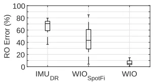
1. First, we proposeWIO, a novel approach to estimate the distance traversed by a subject using WiFi Channel State Information(CSI) measurements collected during decoding of WiFi packets and later fusing them with measurements from inertial sensors. Notably, we propose a method in WIO to also eliminate the impact of undesirable disturbances to the WiFi signals by surrounding moving objects such as humans: an aspect that has never been addressed in prior work. We demonstrate that the design of WIO addresses multiple limitations of prior art,i.e., it : i) does not require fingerprinting or site surveys, ii) is resilient against changes in environment including human movements, iii) works on commodity WiFi devices, iv) requires only a single access point with no modifications, and v) is able to measure distance traversed by humans as well as non-human subjects. Further, we present our implementation of WIO using commodity Inertial Measurement Units(IMUs), WiFi Network Interface Cards(NICs), and Access Points(APs) and extensively evaluate it in a variety of scenarios using both human and robotic subjects. We demonstrate that, on average, WIO measures both long and short distances with an error of<6.28% of the actual distance traversed over time, which is an order of magnitude smaller compared to pure inertial odometry.
2. Second, we proposeWiPolar, a passive multi-person tracking system for commodity WiFi devices that proposes the use of polarimetry (i.e.measuring the polarization of WiFi signals) along with conventional interferometry (i.e.finding Angle of Arrival) to accurately separate and track multiple human reflection signals at a given receiver and derive their locations. We demonstrate for the first time, the feasibility of using polarization diversity for WiFi signals as an additional sensor for separating human reflections. We propose a new CSI denoising technique for multiple-person tracking that removes noise, but unlike prior approaches, preservesboth, amplitude and phase changes in the ambient WiFi signals caused by human movements. Further, we demonstrate for the first time, passive tracking of multiple human targets on commodity WiFi devices without any prior knowledge of the number of human targets. We present our implementation of WiPolar using only commodity WiFi NICs and antennas and extensively evaluate it in a variety of environments with up to 5 human subjects and just 3 to 5 receive antennas. We demonstrate an average tracking error of only 56cm, which is just 9cm greater than the state-of-the-art Wi-Fi based single-person tracking ap-proach. Most importantly, we demonstrate over 73% reduction in overall tracking error due to our technique of polarization-based reflection path matching that highlights the feasibility of using signal polarization for human-tracking with WiFi.
rec-ognizes the gestures of multiple users when the users perform them simultaneously. We demonstrate a novel method to generate virtual samples that enables WiFi based multi-user gesture recognition without requiring multi-users to provide training samples for all possible combinations of gestures and without requiring to separate the contribution of each user’s movements from the net measurements of wireless channel metrics. In addition, we pro-pose a method to automatically identify the number of gestures as well as the start and end times of different gestures when multiple users perform them simultaneously. We present our implementation and extensive evaluation of WiMU on commodity WiFi devices. Our evaluations show that WiMU recognizes 2, 3, 4, 5, and 6 simultaneously performed gestures with average accuracies of 95.0, 94.6, 93.6, 92.6, and 90.9 percent, respectively, which is as accurate as other WiFi-based gesture recognition approaches that support only a single user. 4. Fourth, we proposeLiGest, an ambient light based gesture recognition system, that works
using ambient light generated from any type of light sources, including LEDs and fluorescent lamps, and without requiring any control over the light sources. We develop a method that makes such an ambient light based gesture recognition system agnostic to lighting conditions as well as to the position and orientation of user. We demonstrate an implementation of LiGest using inexpensive commodity light sensors. We present an extensive evaluation of LiGest on a comprehensive real world dataset of 15175 samples from 20 users in 9 positions, 4 orientations, 11 lighting conditions, and 2 different environments, which has since been released to the public and the research community. Our evaluations demonstrate that LiGest achieves anaverage accuracy of 96.36%, similar to (and often higher than) the average accuracies achieved by RF based gesture recognition systems, as well as WiMU, which show the potential of other ambient signals such as ambient light for enabling ubiquitous sensing.
1.3
Thesis Outline and Organization
To inform and demonstrate how our work addresses the current challenges that impede exist-ing ubiquitous sensexist-ing techniques in multiple application domains of distance trackexist-ing, location tracking and gesture recognition, we divide the rest of this thesis into the following four chapters.
Chapter 2 introduces inertial odometry, a technique used to measure distance traversed by an object using inertial sensors such as accelerometers. It then provides a background of the ac-celerometer drift problem that significantly affects the accuracy of inertial odometry, along with current solutions that use information from WiFi signals to correct the drift. Finally, it details the limitations of these solutions and how WIO can overcome them to be able to track distance moved by both human and non-human targets, despite the presence of background movements that also introduce undesirable variations to the WiFi signal while correcting the drift.
multiple humans, and then describes WiPolar’s novel technique of introducing polarization diversity in the WiFi signals to track multiple, but unknown number of human targets.
Chapter 4 introduces human gesture recognition with WiFi, a technique used to infer patterns of limb movementsi.e.gestures from WiFi signals. It then motivates why it is not straight-forward for existing WiFi-based gesture recognition approaches to train and recognize simultaneously performed gestures from multiple humans and how WiMU overcomes this challenge.
CHAPTER
2
ENHANCING INDOOR INERTIAL
ODOMETRY WITH WIFI
2.1
Introduction
2.1.1 Motivation:
Odometry is the process of measuring the distance traversed by a subject over a given period of time. Accurate odometry is of fundamental importance in several indoor applications such as in augmented/virtual reality to track user motion, in indoor navigation to improve localization and tracking accuracy of mobile users, in robotics to perform simultaneous localization and mapping, and in gesture recognition to model human movements. While for outdoor scenarios, GPS signals can be used to perform odometry with enough accuracy, for indoor scenarios, accurate odometry is still an unsolved problem.
motion and fitness tracking inside virtual reality. Needless to say that accurate inertial odometry will benefit all other existing indoor applications as well where an IMU can be attached to the subject. Unfortunately, the distance measured through pure inertial odometry faces the well-known problem of large drift errors over time[Jim10]. These errors occur because the acceleration values reported by the commodity IMUs are prone to bias (i.e., a small offset in the average signal output, even when there is no movement), and further contain non-negligible thermal and mechanical noise due to temperature dependencies, mechanical faults, and calibration errors[Fle05]. Consequently, when these acceleration values are integrated to measure the distance moved by the subject over the given period of time, the error in each value also gets integrated and continues to grow during subsequent integrations, resulting in the large drift errors. Due to these drift errors, pure inertial odometry is widely considered unusable in most real-world applications[Abd13; Tia17; Cho11].
A common approach to addressing the problem of large drift errors in pure inertial odometry is to augment it with an auxiliary source of information, such as a camera, and use that information to correct the drift[Kel11]. In this chapter, we focus on using WiFi signals as the source of auxiliary information. Our motivation behind using the WiFi signals is the same as behind focusing on inertial odometry: just like IMUs, WiFi communication has become very power efficient and is available on most modern hand-held and wearable computing devices. Even in the majority of the other indoor applications, such as those that we mentioned at the start of this section, WiFi communication is either already being used, or can be enabled at negligible cost. This, coupled with the observation that most modern indoor environments these days already have one or more WiFi access points (APs) with which these WiFi enabled devices communicate, makes WiFi our preferred source of auxiliary information.
2.1.2 Limitations of Prior Art:
Researchers have indeed previously explored the use of WiFi signals as the source of auxiliary information. Prior work that leverages WiFi signals for this purpose can be divided into two broad categories: received signal strength (RSS) based schemes[Wan12; Mal13; Pan14; Zam15]and channel state information (CSI) based schemes[Li16a; Li16e; Mah17]. Next, we describe the limitations of prior schemes belonging to these categories.
2.1.2.1 Limitations of Prior RSS-based Schemes
and matched with the fingerprinted RSS values to get the auxiliary position estimates, which are then used to correct the drift. This fingerprinting-based approach has two key limitations. First, manual collection of RSS fingerprints is a strenuous and unscalable task. Second, fingerprinting-based approach works only if the indoor environment stays perfectly static; a small change, such as moving a piece of furniture or a human moving around, drastically changes the fingerprints of the environment.
2.1.2.2 Limitations of Prior CSI-based Schemes
The CSI-based schemes have also adopted two approaches. The first approach is to use CSI mea-surements to frequently calculate the angle of arrival (AoA) of each direct-path signal arriving at the WiFi receiver from each of the several APs deployed in an outdoor environment, and use the changes in the AoA values of those direct-path signals as the auxiliary source of information to correct the drift. This AoA-based approach has two key limitations. First, it does not work well in indoor environments, especially on commodity WiFi devices, because indoor environments have large number of multipaths that cannot be easily resolved to identify the direct-path signal using the limited number of antennas (usually no more than three) that come with commodity devices. Second, it requires multiple APs. While the use of multiple APs is theoretically possible, practically, it gives rise to three problems: 1) a WiFi device cannot switch between APs very fast due to the several hundred milliseconds (up to 600ms[Giu09; Ban06]) that it takes for a WiFi device to handshake with an AP to connect with it, making real-time tracking of changes in position impractical; 2) even if the WiFi device could somehow switch between APs instantaneously, it would no longer be able to perform its primary function: sending and receiving data; 3) many environments, such as homes, contain only a single AP. While a WiFi device mightseesignals from the APs of neighbors, to collect CSI measurements, it needs to receive packets from the AP and for that, it must first connect to the AP. This is problematic because most APs these days are password protected. The second approach is to use CSI measurements to first calculate the power delay profile (PDP) and then estimate the velocity of the subject, and use this estimate to correct the drift. The key limitation of this approach is that as the maximum bandwidth that a WiFi channel can have is 80MHz, the distance resolution achievable using PDP is limited to(3×10⁸)/(80×106) =3.75m, which is too coarse.
2.1.2.3 Limitations of PDR-based Schemes
2.1.2.4 A Common Limitation of All Prior Schemes
As reflections from the objects moving in the vicinity of the subject significantly impact WiFi signals, all prior WiFi-assisted schemes assume that no other objects or humans other than the subject move in the environment while WiFi signals are used for odometry. This is an important practical limitation because in most real-world indoor environments where odometry finds applications, there will almost always be objects, especially humans, moving in the vicinity of the subject.
2.1.3 Problem Statement:
In this work, our objective is to develop a scheme that uses the ubiquitously present WiFi signals as the auxiliary source of information to correct the drift errors in inertial odometry, and thus enable accurate measurement of distance traversed. The scheme should further address all the limitations of prior art,i.e., it should: 1) work indoors, 2) not require fingerprinting, 3) be resilient against changes in environment including human movements, 4) work on commodity WiFi devices, 5) require only a single access point with no modifications, and 6) be able to measure distance traversed by humans as well as non-human subject.
2.1.4 Proposed Approach:
We propose WIO, a WiFi-assisted Inertial Odometry technique that accurately estimates the distance traversed by the subject in any given indoor environment while satisfying all six requirements. WIO requires the subject to be equipped with an IMU and a WiFi NIC connected with an AP. Examples of such a subject are: a human carrying a smart phone; a robot or a drone with on-board IMU and WiFi NIC. To measure the distance traversed by the subject, as the subject moves, WIO continu-ously collects acceleration measurements from the IMU and channel state information (CSI) from the WiFi NIC and periodically (every second) estimates the distance traversed by the subject. To estimate the distance traversed, in each one-second measurement period, WIO first obtains two estimates of the distance traversed by the subject during that measurement period: one estimate from the acceleration measurements and the other from the CSI measurements. It then employs a Kalman filter[Mei83]to correct the drift in the distance estimate obtained from the acceleration measurements using the distance estimate obtained from the CSI measurements, and returns an accurate estimate of the distance traversed by the subject until that measurement period.
AP
1. Device moves 2.WiFi path length changes
NIC NIC
IMU IMU
i. Path length change estimation of all multipaths in Frequency Domain
ii. Path selection (most parallel to direction of motion) iii. Direction/angle approximation of selected path iv. Distance computation from selected path
i. Bias removal ii. Velocity estimation iii. Distance computation CSI
(Δd)
3. Distance estimation using WiFi
4. Distance estimation using IMU Accln.
IMU Dist. WiFi Dist.
Total Distance 5. Fusion
Kalman Filtering
Figure 2.1 Steps performed by WIO to measure distance traversed
distance moved by the subject) changes. As a transmitted WiFi signal arrives at the WiFi NIC from multiple paths due to the reflections in the indoor environment, and the length of all these paths change as the subject moves, multiple frequencies appear in the CSI measurements. To estimate the distance traversed by the subject during any given measurement period, WIO first identifies and isolates the most suitable signal propagation path among all the paths. Next, it measures the change in the length of this path by looking at the frequency that this path introduces in the CSI measurements. Finally, it uses this value of the change in the length of this path along with the direction of motion of the subject with respect to this path, and applies appropriate trigonometric operations to obtain the estimate of the distance moved by the subject during the given measurement period. Note that all these three steps (i.e., identifying and isolating a suitable path, identifying the frequency that this path introduces in the CSI measurements, and estimating the direction of motion of the subject with respect to this path) are very challenging, and we will present solutions to these challenging problems in this chapter.
2.2
Related Work
In this section, we first describe the prior schemes that use WiFi signals as the auxiliary source of information to correct drift errors. After that, we give a brief overview of the WiFi-based localization schemes and describe their limitations if used for odometry. Finally, we give an overview of auxiliary sources of information other than WiFi that researchers have proposed to use.
2.2.1 WiFi Assisted Inertial Odometry
As mentioned in Sec. 2.1, prior work that leverages WiFi signals can be divided into two broad categories: RSS-based and CSI-based. We already described the limitations of the prior RSS-based and CSI-based schemes in Sec. 2.1. Here, we briefly describe the methods used inside these schemes.
2.2.1.1 RSS-based Schemes
performing odometry, it compares the observed RSS value of the signal from each AP with the RSS value in the fingerprint database and estimates the distance from each AP. Next, it uses multilat-eration to get the absolute coordinates of the subject to which the WiFi receiver is attached and uses this absolute location to correct the drift. It further uses PDR as another source of auxiliary information. Using this approach, Unloc achieves a resolution of 1-2m. Zee[Rai12], WILL[Wu13], and LiFS[Yan12]also use multiple APs and employ approaches that are very similar to Unloc, except that they propose crowdsourcing-based methods to generate the fingerprint database. Zee achieves a resolution of 2.3m, while WILL and LiFS both achieve only room-level resolution. Researchers have proposed several other schemes that follow similar approaches of generating RSS fingerprints, estimating position related properties of the subject, and using those estimates to correct the drift
[Kot12; Pan14; Che14b; Mir13].
WAP uses an RSS-distance model and plugs the relative changes in the observed RSS values into that model to estimate the distance moved by the subject, and uses this estimate to correct the drift[Hon14]. Among all RSS-based methods, it achieves the highest resolution of 71cm, but with using 15 APs. Other approaches that employ some sort of RSS-distance model to obtain the auxiliary information include WiBEST[Hu13a]and those proposed by Kemppiet al.[Kem10]and Malyavejet al.[Mal13], which achieve a resolution of 42cm, 1.2m, and 1m respectively. Finally Schatzberget al.
[Sch14]proposed a method to use the time-of-flight (ToF) of the signal between the WiFi device and the AP to estimate distance between them and use that estimate along with the distance estimates obtained using PDR and RSS-distance model to correct the drift. Unfortunately, their scheme works only when there is line-of-sight (LoS) between the WiFi device and the AP, and achieves a resolution of 2.5m. In comparison with prior RSS-based schemes, WIO neither uses RSS-based distance models nor requires multiple APs or fingerprinting, works on both human and non-human subjects, and achieves an order of magnitude finer resolution.
2.2.1.2 CSI-based Schemes
Note that while SAIL uses only a single AP, its key limitation is that it is designed only for pedestrians and thus further requires prior training to associate a user’s step length with distance, which can vary across activities such as running and walking. In comparison with all prior CSI-based schemes, WIO only requires a single AP, works using commodity devices, performs odometry for both human and non-human subjects, is resilient to environmental disturbances, achieves an order of magnitude better resolution, and is agnostic to the direction of motion of the subject and the path it follows.
2.2.2 WiFi-based Localization
Researchers have done a significant amount of work on WiFi-based localization, with the best schemes that do not require fingerprinting achieving a positioning error of as low as 23cm[Xio13a]. Some of the prominent localization schemes include ArrayTrack[Xio13a], SpotFi[Kot15], CUPID
[Sen13], CUPID 2[Sen15], UbiCarse[Kum14], SpinLoc[Sen12a], and several more. One might argue that by doing periodic and frequent rounds of localization, one can actually estimate the distance through which a subject moves. There are five limitations of such an approach. First, the smallest localization error that any scheme achieves is 23cm. This 23cm error is seen in each of the multiple localization rounds that are done to measure the distance. Consequently, the net error in the estimated distance is far larger than 23cm. Second, several localization schemes, such as UbiCarse, and SpinLoc, require the antennas of the WiFi device to be manually rotated every time a localization is desired. This makes localization-based odometry infeasible on devices that are not carried by humans and/or have unmovable antennas. Third, several localization schemes, such as CUPID and SAIL employ PDR, which again limits them to only humans carrying the WiFi device. Fourth, all localization schemes require multiple APs, which leads to the same three problems mentioned in Sec. 2.1 underLimitations of Prior CSI-based Schemes. Fifth, several existing schemes, such as Chronos[Vas16], ToneTrack[Xio15], and Splicer[Xie15], require the WiFi device and the APs to hop across multiple channels. Such channel hopping is infeasible in practice because channel hopping requires both WiFi receiver and WiFi AP to hop across all WiFi channels in sync with each other and also multiple times a second. Such hopping requires explicit coordination among the WiFi receiver and the WiFi AP, which is not supported by any IEEE 802.11 standard. Furthermore, all other WiFi devices associated with such an AP will also have to switch channels at a very high speed in sync with the AP, which will make it difficult for them to achieve any useful data transfer.
2.2.3 Other Auxiliary Information Sources
Researchers have also proposed methods that use several other sources of auxiliary information such as cameras[Sca11], barometer[Zha12], polarized light[Tia17], PDR[Fox05; Jay13], ultrasonics
a robot can use camera as the auxiliary source of information when there is enough light, and switch to our WiFi-based auxiliary source of information when it passes through dimly lit or unlit surroundings.
2.3
Distance Estimation Using WiFi
In this section, we describe how WIO uses WiFi signals to estimate the distance traversed by a subject. Consider a subject, such as a human or a robot, that wants to estimate the distance it traverses in an indoor environment. The subject is equipped with a WiFi NIC and the indoor environment has a WiFi AP. Let this subject (and thus the WiFi NIC) move by a small distance∆d over a time interval
[t,t+∆t]. Fig. 2.2a shows an example where the gray and black squares represent the positions of a
Δd AP
k
(a) LoS
Δd AP
k
(b) NLoS
Δd θ {t}k
≈ θ {t}k θ {t+Δt}k
(c)θk{.}as the subject moves
d k
k k
19.6° 13.2°
2.6°
(d)∆θk
Figure 2.2 Estimating the change in the length of the path from an anchork(i.e.the AP or a reflector) while
the subject moves a distance∆d during a time interval[t,t+∆t]) in (a) LoS; (b) NLoS with initial path length
lk{t}at timetand initial angle of arrivalθk{t}at timet; (c) approximatingθk{t+∆t} ≈θk{t}to estimate
path length change∆lk; (d) selecting the anchor that leads to the smallest change in the angleθk{.}as that
anchor whose path to the subject is the most parallel to the direction of motion of the subject.
per the triangle law of cosines[Nel93],∆θk approaches zero,i.e.∆θk≈0, and the two paths with lengthslk{t}andlk{t+∆t}can be treated as approximately parallel. With this approximation and representing|lk{t+∆t} −lk{t}|with∆lk, it is straightforward to see from Fig. 2.2c that
∆d≈ ∆lk
|c o s(θk{t})| (2.1)
The reason behind using the absolute values in the equation above is that we are measuring distance, not displacement. WIO uses this equation to estimate the distance traversed by the subject during any given measurement period of duration∆t. To estimate the distance traversed by the subject over any desired duration of time using solely the WiFi signals, WIO can simply aggregate the estimated values of distance from multiple consecutive measurement periods spanning that duration of time. However, as our objective is to use WiFi signals to correct drift based errors in pure IMU-based odometry, we use these estimated values of distance from each measurement period to minimize that drift. We will now describe how to estimate the values of∆dusing WiFi signals and then describe the process of using these estimates to minimize the drift shortly, in the next section.
To accurately estimate the values of the distance,∆d, moved in any given measurement period, WIO needs to
1. ensure that the approximation∆θk≈0 is valid,i.e., the path at the start of a measurement period is approximately parallel to the path at the end of that measurement period;
2. estimate the change,∆lk, in the length of the path from the anchork to the subject between consecutive measurement periods;
3. estimate the angleθk{t}made by the path from the anchork with the subject at timet; and 4. eliminate the impact of any moving objects.
In the next four subsections, we describe how WIO performs these four tasks.
2.3.1 Approximation∆θk≈0
The approximation∆θk ≈0 has been widely used in literature in both MIMO radar[Zha10; Ben10] and localization[Kot15; Xio13a; Kum14]to estimate the change in path length across twoantennas. We are using it to estimate the change in path length across twopositions. To ensure that this approximation holds, we make two design choices. First, WIO keeps∆t small so that the distance ∆dtraversed by the subject during∆tis very small compared to the path lengthslk{t}andlk{t+∆t}. Second, in any given measurement period, WIO selects the signal coming from that anchor whose path to the subject is the most parallel to the direction of motion of the subject because such an anchor inherently makes the smallest∆θk compared to any other anchor. For example, Fig. 2.2d shows three anchorsk,k0, andk00, and their corresponding∆θ. The path from anchork to the
subject is the most parallel to subject’s direction of motion, and we see in Fig. 2.2d that∆θk is smaller compared to both∆θk0and∆θk00.
the first design choice is easy, implementing the second design choice is very challenging due to the lack of any prior information about the existence and the spatial distribution of the anchors in the environment. As the selection of the anchor directly impacts the value of∆lk, the anchor selection process is intertwined with the estimation of∆lk. Thus, we discuss the technical details of anchor selection process in the next subsection along with the technical details of estimating∆lk.
2.3.2 Estimating∆lk
To estimate the value of∆lk,i.e., the change in the length of the path from the anchorkto the subject between any given pair of consecutive measurement periods, we leverage the channel frequency response (CFR)-power model presented in[Wan15]that quantifies the impact of the movement of objects in the environment on the CFR observed at a stationary receiver. Next, we first briefly describe the CFR-power model for a stationary receiver and moving objects, and then explain how we repurpose it for use on a mobile subject to estimate∆lk.
2.3.2.1 CFR-power Model[Wan15]
Consider a transmitted signal with carrier frequencyf that arrives at the receiver fromN paths. LetH(f,t)represent the CFR at timet,ak(f,t)represent the complex valued attenuation and initial phase of thekthpath, andτk(t)represent the propagation delay of thekthpath. Consider a pathk that is reflected from an object that moves by a small distance from time 0 tot causing a change in the length of pathk fromlk{0}tolk{t}. The propagation delay of this path at timet isτk{t}=lk{t}/c, wherec is signal speed. The phase shift experienced by signal on this path is 2πlk{t}/λ, whereλ=c/f is carrier wavelength.
Let us express the total CFR as the sum of dynamic CFR,Hd(f,t), and static CFR,Hs(f). Dynamic CFR is the sum of the CFRs for the paths in a setPd whose lengths change due to the movements of the object in the environment, and is given byHd(f,t) =
P
k∈Pdak(f,t)e−j2πlk{t}/λ. Static CFR is the sum of CFRs for all remaining paths whose lengths do not change. Letvk represent the rate at which the length of thekthpath changes as the object moves by a small distance from time 0 to time t,i.e.,vk=∆l/t. Thus,lk{t}=lk{0}+vkt. Wanget al.showed in[Wan15]that the instantaneous total CFR power at timet can be expressed as:
|H(f,t)|2=Xk
∈Pd2|Hs(f)ak(f,t)|cos
2πv
kt
λ +2πlλk{0}+φs k
+Xk
∈Pd|ak(f,t)|
2+
|Hs(f)|2
+Xk,l
∈Pd;k6=l2|ak(f,t)al(f,t)|cos
2π(vk−vl)t
λ +2π(lk{0λ}−ll{0})+φk l
(2.2)
where 2πlk{0}/λ+φs kand 2π(lk{0} −ll{0})/λ+φk lare constants representing initial phase offsets.
2.3.2.2 Using CFR-power Model to Estimate∆lk
fourier transform (STFT) and discrete wavelet transform (DWT), we can identify the frequencies present in the CFR power and use them to estimate the rates at which the lengths of different paths are changing.
Now instead of the WiFi receiver being stationary and the objects in the environment moving, if the WiFi receiver moves (and some anchors are stationary and some may be mobile) during a measurement period∆t, then the net effect is similar: the length of the path from any given anchor
k to the receiver changes at the ratevk=∆lk/∆t. Recall from Sec. 2.3.1 that we select only a single anchor whose path to the subject is the most parallel to the direction of motion of the subject, and thus have to handle only a single path whose length changes. Thus, Eq. 2.2 reduces to a single sinusoid of frequencyFk =vk/λHz. If WIO could automatically estimate the value ofFk while selecting such an anchor, then it can calculate∆lkas∆lk=vk∆t =Fkλ∆t. Thus, Eq. (2.1) becomes
∆d≈ Fkλ∆t |c o s(θk{t})|
(2.3)
In this equation,λand∆t are constants and already known. Next, we describe how WIO estimates the value ofFk while selecting a single appropriate anchor.
2.3.2.3 EstimatingFk
Commodity devices report CFR values in the form of CSI measurements. LetNT x andNR xrepresent the number ofT x andR xantennas, respectively, and letSrepresent the number of subcarriers between eachT x-R xpair. Each CSI measurement is essentially comprised ofS×NT x×NR xCFR values, one for each subcarrier between eachT x-R xpair. As WiFi network interface cards (NICs) generate CSI measurements repeatedly, we essentially obtainS×NT x×NR xtime-series of CFR values. As our approach is based on the CFR-power model, we multiply each value in each time-series with its complex conjugate to obtain CFR power values. Onward, we will call each time-series of CFR power values aCFR-stream. Next, we first describe how WIO removes noise from the CFR-streams. After that, we present the method that WIO uses to estimate the value ofFkfrom these denoised CFR-streams while selecting an appropriate anchor.
2.3.2.3.1 Noise Removal
PC-stream and applies the second denoising step on the remaining PC-streams. The PCA based noise removal is a well-studied topic and we refer interested readers to[Wan15; Vir17a; Ven18]for more details.
In the second denoising step, WIO removes any left over noise from each of the remaining PC-streams using Savitzky-Golay (SG) filter. We chose SG-filter because it smooths out high frequency noise while preserving the heights of the peaks in the original signal caused by the movements of the subject. The SG-filter slides anm-point window over the entire signal and smooths each
m-point interval by fitting annthorder polynomial that minimizes mean squared error. The key challenge in effectively applying SG-filter is to automatically determine the appropriate value form. To address this challenge, we leverage the fact that the frequencies introduced by the noise have much smaller power compared to the frequencies due to the changes in path lengths as the subject moves. Thus, to set the value ofmfor any given PC-stream, WIO first identifies the highest frequency that significantly contributes to the overall signal power in that PC-stream. We call this frequency a knee-frequency fk n e e. It then setsm=1/fk n e e, and applies the SG-filter to smooth out all the frequencies greater thanfk n e e.
To identify fk n e e, WIO traverses the cumulative sum of the power spectrum (CSPS) of the given PC-stream from the highest frequency in the spectrum to the lowest and maintains a running average and standard deviation. While traversing, as soon as it encounters a value that is one standard deviation below the running average, it declares the frequency at that value asfk n e e. To illustrate this, Fig. 2.3a shows a PC-stream and Fig. 2.3b shows its CSPS. We observe from Fig. 2.3b that there is a long tail from 90Hz down to 17Hz due to noise frequencies. At 17Hz, there is a sharp drop showing that the majority of the power in the PC-stream is contributed by frequencies less than 17Hz. These are the frequencies introduced by the movements of the subject. As there is a large deviation at 17Hz, WIO automatically identifies 17Hz asfk n e e using this standard-deviation based method.
Regarding the value ofn, WIO simply setsn=1 because the signal variations within anym-point interval are all due to noise, which after smoothing will generate a straight line anyway. For example, a noise frequency of 50Hz added on top of a signal frequency of 17Hz will result in a straight line segment of the 17Hz signal every time it is smoothed in a time window greater than 1/50 sec such as whenm=1/17 sec. We call the PC-streams obtained after applying SG-filter ‘denoised-streams’ and represent theithdenoised-stream withDi. Note thati6=1 becauseD1would correspond to the first PC-stream, which we discarded during the first denoising step. Fig. 2.3c shows the denoised-stream obtained after applying SG-filter on the PC-stream in Fig. 2.3a.
2.3.2.3.2 Frequency Estimation Along with Anchor Selection
0 0.33 0.66 1 Time(s) 0 0.2 0.4 0.6 0.8 1 Norm. Power
(a) Left-over noise in PC-stream
0 17 40 65 90
Frequency(hz) 0 0.2 0.4 0.6 0.8 1 CSPS
(b) CSPS of PC-stream in Fig. 2.3a
0 0.33 0.66 1
Time(s) 0 0.2 0.4 0.6 0.8 1 Norm. Power
(c) Denoised PC-stream with SG-filter
Figure 2.3 Using SG-filter to remove noise from PC-streams leftover after PCA
∆dbetween timet andt+∆t, as shown in Figs. 2.2b and 2.2c. Let the lengths of the paths from the anchor to the subject at timest andt+∆t belk{t}=L1andlk{t +∆t}=L2, respectively, and the
angle changes by∆θk. Then,L1,∆d, andL2form a triangle with∆θkbeing the angle opposite to the side∆d. As per the law of cosines,∆d2=L21+L22−2L1L2c o s∆θk. Through simple algebraic manipulations, we get|L2−L1|=p
∆d2+2L
1L2(c o s(∆θk)−1).
This expression states that the change in the length of the path,i.e.,|L2−L1|, from an anchor
is maximum when∆θk =0. It further states that|L2−L1|reduces with increase in∆θk. Recall that ideally, our desired anchor is the one whose path to the subject is parallel to the direction of motion of the subject,i.e.,θk{t}=0,θk{t+∆t}=0, and thus,∆θk{t}=0. Thus, the best anchor among all the anchors is the one for which the change in path length|L2−L1|is the highest because
this anchor will have the smallest value of∆θk{t}(and thus the most parallel path) among all the anchors.
Let us represent|L2−L1|with∆lk. Recall from Sec. 2.3.2.2 that∆lk=Fkλ∆t. Asλand∆t are constant,∆lk∝Fk. As the best anchor has the highest value of∆lk among all anchors, the change in the length of the path from this anchor to the subject introduces the highest frequency in the CFR power.Therefore, given any denoised-streamDi, WIO selects the anchork whose path to the subject is the most parallel to the direction of motion of the subject by identifying the highest frequency
with non-negligible magnitude and using that frequency asFki.
To identify the highest frequency in each measurement period in any given denoised-stream, WIO first applies FFT on the denoised-stream in that measurement period. Next, it normalizes all FFT magnitudes using max-min normalization to bring them in the range of 0 and 1. Finally, it selects the highest frequency with non-negligible normalized FFT magnitude (i.e., magnitude greater than 0.25) as the desired frequencyFki. It is possible that this method will sometimes lead to over- or under-estimation errors. To address this problem, WIO selects the median of allFki calculated from multiple denoised-streams as the final value forFk because median values are less affected by over- and under-estimation errors.
2.3.3 Estimatingθk{t}
A seemingly straightforward approach to estimate the angleθk{t}made by the path from anchor
algorithm and calculate the AoA of the path from each anchor to the subject. MUSIC algorithm correctly resolves the AoAs of paths only when the CFR values are captured using at least as many antennas as the number of dominant multipaths. In typical indoor environments, there are 4 or more dominant multipaths[Xio13a]while typical commodity devices have only up to 3 antennas. Thus, the MUSIC algorithm yields errors as large as 50◦[Kot15]when used on commodity devices. SpotFi proposed a super resolution method to estimate AoAs using commodity WiFi NICs but only with 2◦to 5◦smaller error[Kot15]. Unfortunately, this error is still too large to be usable for accurate odometry.
To address the challenge of the inability to accurately estimateθk{t}on commodity devices, we take an unconventional approach. Instead of trying to estimateθk{t}accurately, we simply use |cos(θk{t})|=1,i.e.,θk{t}=0 orπ. The motivation behind this choice is that when WIO selects the highest frequency with non-negligible magnitude asFk(as described in Sec. 2.3.2.3), it is essentially selecting the anchork whose path to the subject is the most parallel to the direction of motion of the subject. Thus,θk{t} ≈0 orθk{t} ≈π. In practice, however, as the number of anchors are finite, the path to the subject from the anchor corresponding to the highest frequency may not be exactly parallel to the direction of motion of the subject. To cater for this, we allow for a±18◦variation in this angle (180◦divided by about 5 multipaths≈36◦, which is the total range covered by±18◦) and correct
the distance estimate with anexpectederror due to this±18◦variation. As each measurement period spans a very small duration∆t, to move through practically observable distances, the subject takes a large number of measurement periods, and thus, the error that manifests in the distance estimates indeed equals the expected error, which makes this expectation based correction feasible. Next, we derive the expected error.
Let the ground truth value ofθk{t}beΘ∈[−18◦,+18◦]. If we use the ground truth value ofθk{t}, then as per Eq. (2.3),Fkλ∆t =∆d|cos(Θ)|. However, as we use|cos(θk{t})|=1, thenFkλ∆t =∆d+ε, where epsilon is the error due to the use of|cos(θk{t})|=1. Equating the right hand sides of these two equations, we getε=∆d|cos(Θ)| −∆d. The expected error can now be calculated by averaging it over the range ofΘ. Thus, the expected error is derived asE[ε] = 2π/∆d10R−+π/π/1010(|cos(Θ)| −1)dΘ
≈ −0.01637∆d. Consequently, we getFkλ∆t =∆d+ε=∆d(1−0.01637). Thus, we get the following equation, which WIO uses to estimate∆d in each measurement period.
∆d≈1.0166Fkλ∆t (2.4)
2.3.4 Eliminating Disturbances due to Humans/Mobile Objects
2.3.4.1 Intuition
We saw from Eq. 2.2 that the CFR power has two sets of sinusoids. Lets call the frequencies of the first set of sinusoids (i.e., those with argument 2πvkt/λ) asprimaryfrequencies and the frequencies of the second set of sinusoids (i.e., those with argument 2π(vk−vl)t/λ) assecondaryfrequencies. The secondary frequencies are essentially the pairwise combination of all primary frequencies. Thus, if there arek primary frequencies in the CFR power, then there will be k2secondary frequencies in it. As we have discussed before, when the subject moves, the length of the path from each anchor to the subject changes. Thus each anchor introduces a primary frequency to the CFR power that is proportional to the extent by which the length of its path to the subject changes. If the number of anchors isk, then they introducekprimary frequencies and k2secondary frequencies, making the total number of frequencies in the CFR power equal tok+ k2.
Note that the sinusoids in Eq. 2.2 are of the form cos(ω{t}+φ), which can be written as cos(ω{t})cos(φ)−sin(ω{t})sin(φ), whereω{t}is time varying whileφis a constant offset. The underlined terms in this expression are time varying while the others are constant. This shows that each sinusoid in Eq. 2.2 has a cosine component and an orthogonal sine component. Consequently, when we apply PCA, any given sinusoid is essentially projected along two orthogonal basis vectors. Thus, PCA projects each sinusoid along a unique pair of orthogonal basis vectors. This leads to an importantinsight:thek+ k2sinusoids introduced by thekanchors in the CFR power should appear alongNk=2×(k+ k2
) =k(k+1)orthogonal basis vectors after applying PCA.
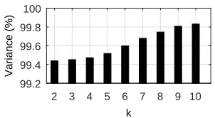
To demonstrate this, we conducted a simulation using values ofk in the range of 1 to 10. For any given value ofk, we randomly selectedk frequency values under 100Hz and calculated their pairwise differences to get another k2frequency values. The motivation behind keeping frequency values under 100Hz is that in indoor environments, the typical movement speeds of both human and non-human objects do not give rise to frequencies above 100Hz in the CFR power[Wan15; Wan16]. Next, we generated sinusoids corresponding to each of thesek+ k2frequency values with randomly selected amplitude and initial phase offset, and added allk+ k2sinusoids to get a hypothetical timeseries of CFR power. We generated 270 such hypothetical timeseries of CFR power using same
k+ k2frequency values but different random amplitudes and initial phase offsets in each of the 270 timeseries. We generated 270 timeseries because in a typical setting whereNT x =3,NR x=3, and number of subcarriers=30, we get 270 CFR-streams. Next, we applied PCA on these 270 timeseries and calculated the amount of variance represented by the firstNk=k(k+1)principal components. Fig. 2.4 shows the value of this variance fork=2 to 10. We see that for eachk,Nk=k(k+1)principal components accounted for over 99.4% of all the variance in the 270 timeseries. This empirically validates our insight.
2 3 4 5 6 7 8 9 10 k
99.2 99.4 99.6 99.8 100
Variance (%)
Figure 2.4 Percentage of variance contributed by the firstk(k+1)principal components
containing the variations due to the sinusoids introduced by the human anchors to appear after the principal components containing the variations due to the stationary highly reflecting anchors. Thus, by only keeping the top few principal components and discarding the remaining, WIO can eliminate the impact of movements of any objects in the environment.
2.3.4.2 Filtering Disturbances due to Moving Objects
Several prior studies, such as[Xio13a; Kot15], have shown that in typical indoor environments, the number of dominant multipaths (and thus the number of anchors) is 4 or more. Thus, in the absence of any moving objects, there should be more thanNk =4(4+1) =20 frequencies in the CFR power. If a human or any other object is present in the indoor environment, then there will be an even larger number of dominant frequencies in the CFR power. Thus, we can safely assume that the variations seen in the first 20 PC-streams are due to the changes in the path lengths between the stationary anchors and the subject. Therefore, to remove the impact of disturbances due to movements of any objects other than the subject, WIO uses only PC-stream numbers 2 through 20 and discards the rest, and performs all its operations described in Sec. 2.3.2.3 under “Frequency Estimation Along with Anchor Selection” on these 19 streams.
2.3.4.3 Discussion
Prior work on WiFi based activity and gesture recognition, such as[Wan15; Vir17a; Yu18; Ven18], proposed to use principal components 2 and 3 (and sometimes 4) to recognize human movements. Yet, here we are saying that the human movements manifest beyond the 20thprincipal component.
This is because there is an important difference between our work and prior schemes: in our work, the WiFi receiver is moving, while in prior works, WiFi receiver was always stationary. Consequently, unlike in our setting, in prior works, the lengths of the paths from the strong reflecting surfaces (such as walls) to the WiFi receiver did not change and thus did not introduce any frequencies. The only frequencies were introduced by the human movements and thus, in prior works, human movements dominantly appeared immediately in principal components 2 and onward.
2.3.5 Summary of Steps