SUMMARY OF COMMANDS AND EXECUTION TIMES
Word Micro- Word
Micro-Command Times seconds Command Times seconds
-Load A 2 266 Shift AD Left Arithmetic! Logical 28* 3724*
Load B 2 266 Shift AB Right Arithmetic / Logical 28 3724*
Load C 2 266 Float Shift A Left Arith metic 28 3724
Load D 2 266 Float Shift A Ldt Logical 28 3724
Load Index 2 266 Float Shift A Left Logical CJo::icd 28 3724
Load X 2 266 Float Shift AB Left Arithrn dic 28 3724
Store A 2 266 Float Shift AJ3 Left Arithmetic/Logical 28 3724
Store A Repeat l(X+Z) 133 Jump Unconditionally (OPS- (OPS -CIS)
(X+2) CIS) U3
Store B 2 266 Jump A Zero 2 266
Store D 2 266 Jump A Negative 2 26(,
Exc hange A and B 2 266 Jump A Low Bit 2 266
Exchange A and C 2 266 Jump Inde ~ 2 266
Ext: h~mge A and D 2 266 Jump Overflow 2 266
Exchange A and I 2 266 Jump Parity Error 2 266
Replace A With I 2 266 Stop--Jump Resume * :'
..
Replace I With A 2 266 Jump Record Address 0 (OPS- (OPS-CIS)
Exchange A and X 2 266 CIS) 133
Exchange A and X Low Bits 2 266 Jump Record Address (OPS- (OPS.-CIS)
Replace A With X 2 266 CIS) 133
RL'place A With X Low Bits 2 266 Jump Hecord Address C (OPS- (OPS -CIS)
Replace X With A 2 266 CIS) 133
Exchange A and M 2 266 Block Transfer *
*
~vfask~d Exchange A and M 2 266 Scan Tabll.~ Greater Than * *
Replace A With M 2 266 Scan Table Less Than * *
Replace M With A 2 266 Scan Table Equal *
*
Exchange A and Q 2 266 Scan Tabh.: Not Eq,lal * ::<
Replace A With Q 2 266 Scan Analog
*
*
i{('place Q With A 2 266 Scan Digital Input
*
*
Clear A and B 2 266 Inhibit Inkrl'upt On 2 266
Complement A 2 266 Inhibit Interrupt Off 2 266
Merge 2 266 Set Analog Sequence 2 266
Extract 2 266 Activate Control Signal 2 266
R('duce Index 2 266 Digital Input: Flexowriter 2 266
Add 2 266 Digital Input: Toggle Switches 2 266
Subtract 2 266 Digital Input: Teletype Reader 2 266
?1ultlply 27 30 3990 Digital Input: High-Speed Tape Reader 2 266
Multiply 21 24 3192 Digital Input: Console SWltches 2 266
Multiply 14 21 2793 Digital Input: Digitran Switches S26-21 2 266
~ll1ltiply 7 10 1330 Digital Input: Digitran Switches 536-31 2 266
Divide 27 31 4123 Digital Input: Digital Clock 2 266
Djvide 21 25 3325 Digital Input: Group Inputs 2 266
Divide 14 18 2394 Digital Output: FIe xowriter 2 266
Divide 7 11 1463 Digital Output: Output Buffer 2 266
Square Root 16 2128 Digital Output: Single-Bit Outputs On 2 266
Shift A L<:·ft Arithmetic 28>'~ 3724* Digital Output: Single-Bit Outputs Off 2 266
Shift A Right Arithmetic 28>;' 3724* Digital Output: High-Speed Tape Punch 2 266
Shift A Left Logical 28 3724 Digital Output: Multibit Output 2 266
Shift A IZight Logical 28 3724 Digital Output: Logging Typ('write r 2 266
Shift A Left Logical Closed 28':' 3724':' Shift AB Left Arithmetic 28>'~ 3n4~'
~,
TRW -330 Digital Control Computer
VOLUME I
PROGRAMMING MANUAL
(Preliminary)
May 4, 1962
This manual is the property of TRW Computers Company.
It
is made available to customers, prospective customers,
and others, with the express understanding that its contents
shall not be released to any third party.
J\.
Thompson Ramo Wooldridge Inc.
~
TRW Computers Company
(division)SECTION
1
2
3
4
5
6
7
8
TABLE OF CONTENTS
TITLE
Introduction
TRW -330 Characteristics and
Capabilitie s
Memory Organization
Arithmetic and Control Unit
Word Structure and Machine Operation
Computer Control and Maintenance
Panel
Programming Particulars
Commands
PAGE
1-1
2-1
3-1
4-1
5-1
6-1
7-1
SECTION 1
INTRODUCTION
SCOPE OF THIS MANUAL
This manual provides information essential to a general understanding of the
pro-gramming characteristics of the TRW -330 digital control computer, particularly
those characteristic s that are relevant to industrial control applications, for
which the TRW -330 has been designed.
In order that this manual may be used as a basic programming handbook for the
TRW - 330 computer, a detailed breakdown has been included on the computer's
flexible instruction repertoire and its various modes of operationo
In. some cases, where more detailed information is available in separate manuals,
the reader is referred to the place where the detailed information is available.
NOTE
It is the intent of this manual to describe every feature available with the
TRW -330 computer. Therefore some of the material presented here will
probably not be applicable to any given TRW -330 control installation.
SECTION 2
·TRW=330 CHARACTERISTICS AND CAPABILITIES
GENERAL
The TRW - 330 is a
stored~program,digital control computer designed specifically
for real-time industrial control applications.
It
is a 2' s complement bi nary
machine.
The computer is assembled in two or more vertical
rack~and-panelcabinets
bolted together to form a convenient package. Each cabinet is 84 inches high,
23 inches wide, and 24 inches deep.
The general design features of the TRW
=330 computer include the following:
(a)
The circulating registers are completely solid state.
(b)
No vacuum tubes are used in the machine.
(c)
The motor that turns the magnetic drum is an induction type, with
excellent starting characteristics and no tendency to "drop out" during
line fluctuations.
(d)
The time-of-day clock uses mercury-wetted-contact relays.
(e)
The guarded sections of memory are protected by toggle switches or,
where program control of the guard feature is required, by
mercury-wetted-contact relays.
(f)
The analog input system can sample sixty points per second using a
single amplifier, so that only one amplifier is required for each TRW
~330system. Furthermore, the amplifier used is a solid state type, including
the choppers.
MEMORY
The memory of the TRW = 330 computer is a magnetic drum that rotates at
approximately 3540 revolutions per minute.
The drum contains from 64 to
1024 tracks of 128 sectors, or words, per track.
Word time for the TRW -330 computer is approximately 133 microseconds.
Each drum revolution takes approximately 17 milliseconds.
DATA AND INSTRUCTION WORDS
Each word in the TRW =330 consists of 28 binary digits, or bits.
The binary information contained in a TRW =330 word may represent numbers,
alphabetic codes, control patterns, etc. Such words are called data words.
The binary contents of a word may represent
a
computer instruction such as
adds subtract, jump, etc.
These words are called instruction words.
The 28-bit data word consists of a sign bit and 27 magnitude bits.
The 28-bit instruction
~2~dcontains two
fields~a 10=bit command field and a
11,.Y6
=bit operand field;
tyrt>"
Sf
the bits are not used in an instruction word.
The
operand field may contain either an operand address
(ZJJti,leJlbSJ
7. , ... )
or the
operand itself
'1°
1
1
I]LdLbMI,.Jn~~1!.. ,
The long word length provides certain inherent advantages:
it allows direct
addressing of the largest memory the machine can contain; by allowing an
operand to be contained within the instruction, memory storage requirements
are reduced and the need for accessing such constants is eliminated.
This
long word also allows rapid manipulation of messages and coded data.
PARITY CHECKING
Parity is checked on all operations involving memoryaccesso
Each time a word (data or instruction) is stored in memory, a parity bit is
generated and stored with the word.
When,ever the word is read from memory,
another parity bit is generated and co'mparedwith the previously stored parity
bit.
If
the parity bits do not agree, a parity error signal is generated.
DIGITAL INPUT-OUTPUT
The TRW-330 computer can accept on-off signals from external sources,
per-mitting digital inputs from such devices as switches,
relays~paper-tape readers,
time-of=day clocks, contact closures, etc.
Digital output signals can be applied to external equipment such as electric
typewriters, paper-tape punches, relays, solenoids, controllers, etc.
ANALOG INPUT-OUTPUT
Variable voltage s from measuring instruments and transducers can be
auto-matically sampled and converted to digital form by the TRW -330.
Up to 1024
of these analog input signals can be converted to their binary equivalents with
a full=scale accuracy of O.
10/0,
and stored on the memory drum automatically.
The results of control calculations, expressed as binary numbers, can be
automatically converted into voltages or currents to be applied to transducers
or othe r contr
01 device s.
REGISTERS AND COMMANDS
Several registers, numerous command options, and a number of special commands
have been included in the TRW =330 computer to aid programming, increase the
effective speed of the machine, and to solve certain problems frequently encountered
, in industrial control.
The standard computer has five registers (B, C, D, I, and X)
(in addition 'to,. the accumulator A register) that are under the control of the pro=
grammer. All of these registers are switchable with the accumulator.
Three
of these registers (B, C, and D) are addressable, so that their contents can be
used as operands
0Two of these registers and the accumulator
'(A,
B, and D)
are directly storable in the rr
0.
memory. Some of the registers have special
features: one is an
i~x(I) register that can be incremented or decremented
by any amount up to 2
=1.
The X register functions in a float, or shift and
count, command and in s can commands
0A repeat command permits a single word to be re<:orded in sequential sectors
of any track.
Multiply and divide instructions can be performed.in quarter=, half=, and
three-quarter -length increments, as well as full=length; this makes it possible to
match the command length to the word length for these commands, and thus
substantially reduce program running time.
An automatic computer stop command is standard.
The ability to mark the current place in the pr,ogram, branch to a subroutine,
execute the subroutine, and subsequently return to the marked place, is standard
on the TRW
~330.The block transfer feature is standard on the TRW -330; the block may be any
length up to 128 words
~Analog and digital input scan commands and a table search command provide
capabilities that are unusual in a drum computer.
The analog scan, specially
designed for industrial control, allows the program to compare 128 converted
analog inputs against upper and lower limits in 34 milliseconds. Digital in,..
puts can be scanned to detect a change from a previously stored image at the
rate of one line every ten microsecondso
The table search command permits words recorded on the sectors of one track
(comparison track) to be compared with the contents of corresponding sectors
of a specified reference track.
The search can be made for equality between
the comparison word and the reference word, for inequality, for less than, and
for greater than.
The search is masked by a word loaded into one of the working
registers; thus any single bit position, or any combination of bit positions, or
entire words may be compared.
During execution of the table search command, the computer s;equentially
compares each comparison word (results of calculations, inputs, etc.) with
its corresponding reference word.· When the condition sought for is found,
the computer identifies the word, and its location, that satisfies the condition.
For systems entailing heavy logging or tape punching duties, a 512-character
output buffer is available to drive logging typewriters
sFlexowriters, and/or
paper tape punches
0The contents of all computer registers used by the programmer can be
dis-played on the computer, control panel during program execution.
Under
program control, the contents of any register or memory cell may be typed
out on the Flexowriter
9or displayed on the operator
fSconsole display in
modified formo
INTERRUPT
An interrupt feature of the TRW -330 allows the computer program to be
inter-rupted by a switch closure occurring in circuits external to the computer.
Upon receipt of an interrupt
signal~the computer automatically stores the
address of the next instruction as a re-entry address, and then transfers
to the interrupt program. After determining the source and nature of the
interrupt and taking responsive action, the computer returns to the master
control program and continues at that point where it was int errupted. As
many as 112 priority interrupts are available.
PROGRAMMING SOFTWARE AND MAINTENANCE CHECKING
A library of subroutines and interpretive routines is available to extend the
capabilities of the TRW -330 computer to scientific and general-purpose
ap~plications.
Generally speaking, anything that helps the programtner also assists the
maintenance man. Numerous features built into the TRW - 330 for the
benefit of the programmer will aid speedy localization of failures. For
instance, the block transfer comtnand and the table comparison command
(one mode of the scan command), coupled with the parity check, make it
possible to quickly localize a metnory fault. A toggle switch allows the maintenance
engineer to cause the machine to stop at any point, rather than merely record a
parity error.
The flexible command structure and tnetnory organization tnakes it easy to keep
certain tnaintenance progratns, such as the utility package, permanently stored
in the tnachine.
Features that reduce hu:man fatigue and assist in checking programs include:
(a) the ability to retnain seated while stepping through a progratn; (b) easily
read neon bulb displays; (c) only one button need be depressed to step through
an instruction; (d) the stop-on-jutnp SWitch makes it possible to stop at
pre-determined points in the progratn.
TYPICAL TRW.,.330 INSTALLATION
A process control installation by TRW Cotnputers Cotnpany consists typically
of the TRW -330 digital control cotnputer, its analog input-output subsystem,
and one or tnore opt ional subsystems depending upon the requiretnents of the
specific installation. These subsystems may include expanded interrupts,
priority interrupts, selective analog updating, progratnmed computer operations
checks, digital output buffering to logging typewriters, and paper tape
chroma-tograph peak integrators, etc.
SECTION 3
MEMORY ORGANIZATION
GENERAL
The TRW -330 can address directly as many as 1024 tracks and anyone of 128
sectors of each track.
Tracks and sectors are numbered in octal notation. The first track on the
memory drum is numbered 000. The last track on the memory drum is
numbered 177 for a 128 track drum, 377 for a 256 track drum, 777 for a 512
track drum, and 1777 for a 1024 track drum. Sectors are numbered 000 through
177.
In the following paragraphs, the track numbers reserved for special purposes
are listed. In a specific installation, all of these track reservations may not
be required. In those cases, the remaining
special~purposetracks may be
used for general storage.
GENERAL STORAGE
General storage is divided into tracks which are writable under program control,
and tracks which are non-writable
0Non-writable tracks can be written into by
manually throwing a switch during program loading. In general, the control
programs are entered into the non-writable tracks to preclude any possibility
of these
progr~msbecoming inadvertently destroyed during normal operation ..
Writable tracks provide storage for intermediate solution of programmed
com-putations. The ratio of writable to non-writable tracks will vary from one
installation to another, depending upon special requirements. Normally,
writable and non-writable tracks are arranged in groups
of~16.
/J
if;' .1 .
iJ
J(/\f:,,(,~
.•
~(llUl:(i /kOJ~.
~~I,~"H,MEXIC"",R}!;GISTERS
Track numbers 075, 076, and 077 are used to address the B, C, and D
arith-metic registers, respectively. Therefore no tracks on the drum correspond
to these track
addresse~.If these track add;resses are used, the corresponding
arithmetic r'egisters will be addressed.
LOADER- VERIFIER
if
Tracks 000 and 001 contain a permanent Loader-yerifier routine. The programmer
cannot write into this track. The Loader - Verifier is used for entering programs
into other tracks, for verifying their accuracy, for entering scaled dec.imal
infor-mation into the computer to obviate operator conversions, for entering routines at
points designated by the computer control panel breakpoint switches, and for other
utility purposes.
The use of these tracks is described in Section 13.
FAST-ACCESS TRACKS
Track addresses 060, 061, 062, and 06.3 are reserved for temporary storage of
fast-access data. Data may be read from or written into these tracks under program
control. This information can be accessed in one-fourth the time that data can
be accessed on other tracks.
This set of fast-acces s tracks is actually a single track, of 128 words, with
four heads mounted 90 degrees apart. Thus every word on the track can be
accessed from any of the four heads, and thus from any of the four track addresses.
Installations requiring 256 words of fast-access data will also have track addresses
054, 055, 056, and 057 reserved for this purpose.
Since each fast-access track uses four track addresses for 128 words, each set
reduces the total addressable general storage by three tracks, or 384 words.
DIGITAL OUTPUT TRACK
Track 072 is reserved for digital output buffering. The use of this track is
described in Section 8.
ANALOG INPUT TRACKS
Tracks 024 and 025 are reserved for analog input data.
Tracks 064 and 065
are reserved for analog input control. The use of the se tracks is described
in Section
9.
ANALOG OUTPUT TRACK
Track 074 is reserved for analog output buffering. The use of this track is
described in Section 10.
INTERRUPT SYSTEM TRACKS
Tracks 037 and 073 are reserved for entry into and exit from priority interrupt
subroutines. Track 037 contains the response routine entry address for each
interrupt used in the system. When the computer responds to an interrupt, the
address for re ... entry into the main program is stored in track 073.
The sectors on these two tracks used for interrupts is equal to the number of
interrupt lines designed into the specific system. The remaining sectors on
both these tracks may be used for general storage.
The use of the interrupt tracks is described in Section 11.
SECTION 4
ARITHMETIC AND CONTROL UNIT
GENERAL
The TRW -330 has nine arithmetic and control registers. Six of the registers
are available to the programmer; three registers are used for control purposes
and are not directly accessible to the programmer.
Three of the program accessible registers, (A, B, and D), are full word length,
each containing 28 bits. Two of the registers, (C and I), contain 16 bits each,
and one register, (X), contains 8 bits.
Two of the control registers, (N and Y), are 16 bits in length, and one control
register ,(E), is 8 bits in length ..
Associated with the control unit also are three static registers, two indicator
flip-flops, and two to eight interrupt registers
0A REGISTER
The A register, 28 bits long, is the principal arithmetic register.
The contents of A can be stored into or loaded from memory. A holds
the augend, sum, dividend, quotient, multiplicand, and product of
arithmetic operations. It can be shifted left or right, or its contents
exchanged with other registers. The contents of A can be examined
for zero, less than zero, for odd, or for overflow. Data can be
merged into or extracted from A.
B REGISTER
The B register, with 28 binary digits, acts as a secondary arithmetic
register. It holds the least significant half of the double length product
in multiplications, and the remainder in divisions and s quare roots.
The principal function of the B register is to provide temporary storage
for intermediate program results
0B can be loaded from or stored into
memory, exchanged with A, and its contents can be shifted right or left
in conjunction with the A register.
The B register is addressable. Its track address is 075.
C REGISTER
The C register contains 16 binary digits 0
It
can be used as temporary
storage
0The C register
i~used in multiply and divide commands,
I
which destroy any previous data in this registero It is also used in
jump and search commands.
The contents of A and C may be exchanged.
The C register is addressable
oIts track address is 0760
D REGISTER
The D register is a 28-bit register used principally for temporary
storage during calculation. D can be loaded from memory, or its
contents exchanged with the contents of A.
The D register is addressable
oIts track address is 0770
I REGISTER
The
L
or index register
~holds 16 binary digits
0Its principal
purpose is to modify the operand addres s during the execution of
indexed instructions 0 The I register can be loaded from memory
or switched with Ao
Its contents can be decremented or incremented
by any magnitude.
X REGISTER
The X register is an 8-bit register., It can be loaded from memory
or its contents exchanged with the 8 least significant bits of Ao
The
X register is used in shift, scan, and store A repeat commands
0CONTROL REGISTERS
N REGISTER
The 16-bit N register is the principal control register of the TRW
-3300
It is not available to the programmer
oIn the RESUME-STEP mode of
operation, the N register contains the address of the next instructiono
Y REGISTER
The 16-bit Y register is used for intermediate storage of the operand
address, and in the RESUME-STEP mode of operation contains the
non-indexed operand address in non-indexed instructions, or the
modi-fied operand address in indexed instructions, except in multiply and
divide commands
0It
is not available to the programmer
0E REGISTER
The 8-bit E register controls the time required to perform comrrlands
which take more than one word time to execute.
STATIC REGISTERS
The three static control registers are those for track address, for command,
and for com.puter state. These registers are not available to the programmer
oINDICATOR FLIP-FLOPS
The two indicator flip-flops associated with the control register are those for
overflow and for parity error.
INTERRUPT REGISTERS
For those installations of the TRW - 330 that include a priority interrupt system,
registers for priority determination (masking) and for holding interrupts are
included in the arithmetic and control unit. The masking registers are M
registers; the holding registers are
Q
registers. The interrupt registers
may be 8-bit, or 16-bit, or 24-bit, or 28-bit registers, as necessary. The
minimum priority interrupt system may include only an 8-bit
Q
register and
an 8-bit M register; the maximum interrupt system, to handle 112 interrupt
lines, may.include four 28-bit
Q
registers and four 28-bit M registers.
The interrupt registers are described in more detail in Section 11.
SECTION 5
WORD STRUCTURE AND MACHINE OPERATION
GENERAL
The binary contents of a TRW -330 word may represent numbers, alphabetic
code s, control patterns, etc.; the se are called data words.
The binary contents of a word may represent a computer instruction such as
add, subtract, jump, etc.; these words are called instruction words.
DATA WORDS
A data word consists of 28 binary digits, or bits. The first 27 bits represent
the magnitude of the number contained in the word.
The 28th bit represents
the sign of the magnitude. A binary zero in the sign position indicates that
the magnitude is positive. A binary one in the sign position indicates that the
magnitude is negative.
B it Po s itions
Binary Word
Octal
Equivalent
Sign
.1 ...
I
---1
-, -
MAGNITUDE
- - - 1
...
s
2
6
12S!24!23122i21\2o! 191
1817116!1·~114113i ~2:
..
28
27..
0
1
iFororoTo\ oforofo
~\otol~I;lo-!
.
•
0
6
I
o
I
o
I
o
I
o
l
The relationship between the binary and octal number systems makes it
co·n-venient to group the binlfcontents of a data word into groups of three, starting
at the least significant
jIof the word. In this manner it is possible to express
the number octally. The binary and octal equivalents from zero through seven
are tabulated as follows.
BINARY
OCTAL
000
0
001
1
010
2
011
3
100
4
101
5
110
6
111
7
From this tabulation the binary contents of the word illustrated above can be
converted to the octal
equivalent~0600000003.
Negative quantities are expressed in 2's complement in the TRW-330 computer.
To change the sign of any magnitude (positive to negative, or negative to' positive),
it is necessary merely to change, all ones to zeros and all zeros to ones, (including
the sign bit), and add one to the result. Thus, the magnitude of the binary number
in the above example can be expressed as a negative binary number as:
,
,
,
,
S
2423 22\21 20 19!18\17 16 15\14 13\12111110191817 6\514 3 2 1
28
2726~
1 0 0 1
111111\11111111ilri\i!i\il\i\11o-i
,
, . ,
I
1
I
j
.
1
1
7
7
7
7
7
7
7
5
The octal equivalent of this number is 1177777775.
The two numbers, 0600000003 and 1177777775, have equal magriitudes although
their signs are opposite. Each is expressed as the complement of the other.
INSTRUCTION WORDS
An instruction word is made up of 28 binary digits divided into two general fields;
the operation code (command) field, and the operand address field.
~.
Operation COde--1
Operand Address----...J
I
.
I
I
I
Track
"1
4Sector--l
!~f~~~~~~~~~~~9~\-~~r~~i~'~i~I~!~~'~
.
I
I
1
I
,
,
I
>6
t
l
vf
The operation code is contained in the ten high-order bits of the instruction
word. The operand address is contained in the 16 low-order bits of the
instruc-tion word. The operand address consists of two subfields; the sector address
and the track address. Bit position 1S is a spare bit and has no significance in
the instruction word. Bit position 17 is used in TRW-330 computers having a
memory capacity greater than 64 thousand words to expand the track addresses
above 777 S.
I t is convenient to indicate the contents of an instruction word in octal notation.
The operation code, the operand track address, and the operand sector address
should be converted from binary to octal separately according to their fields.
The following example illustrates the binary contents of an instruction word and
its octal equivalent.
BINARY
0
000
111
010
00
000
100
101
1
100
001
\ v v I l
v J
OP CODE
OPT
OPS
;v
OPA
OCTAL
0
0
7
2
0
4
5
1
4
1
In some instructions the contents of the operand address field can be the operand
itself rather than the address location of the operand. In this case the octal
representation of the operand address is not divided into the sector and track
groups as in the example, above, but all 16 bits of the operand address field
are converted directly. The following example illustrates the binary and octal
equivalent of this type of instruction.
BINARY
o
1 00
111
0 1 0
00
0
00 1
00 1
0 11
1 00
00 1
OCTAL
o
4
7
2
o
1
1
3
4
1
The octal number 011341, in this case, is the actual operand rather than the
address of the operand. The largest octal number which can be contained in
the operand address field is 177777. This is equivalent to the decimal number
65,535. Operands which are included in the instruction word are treated as
positive numbers by the computer.
OPERATION CODES
The TRW
~330computer reads instructions
frommemo~yand, execute,s 'them in
proper sequence. An instruction consists of an operation code and ari operand
address. ,The data in the
16
bit operand address field may be the address of
the operand, or, in certain cases,
it
may be the actual operand. In cases
where the command does not require an operand, (shifts, switches, and digital
commands), the data in the operand field, can modify the command.
The operation code is made up of the ten high-order bits of the instruction word.
Bits 20 through 24 make up the basic operation code and the remaining bits act
as command modifiers, or tag bits.
L
BaslC
r
MOdified OP
~o~e1
,
lop
Code
o
=
Normal
1
=
Delayed
1
=
Operand---..
Execution Code - - - '
1
=
Index _ _ _ _ _ _ _ _ _ _ _ _ _ _
_
INDEX TAG
Bit
19
is the index tag bit which modifies the operand address of those commands
requiring operands or the transfer address of jump commands. The basic
operation code together with the index tag bit make up the two least significant
octal digits of the operation c,ode. For example, the basic add command is
XX70. To index this command it is necessary only to add one to the basic
command (XX70
+
1
=
XX71).
All even numb'ered operation codes are un-indexed.
All odd numb'ered operation codes are indexed.
The true ope'rand address of -indexed instructions is the address located in the
operand address field less the magnitude present in the index register: OPA-I.
Since the index register contains
16
bits, it is capable of modifying either the
track address, the sector address, or both. For example, if the apparent
address is 042-036,
and the contents of I correspond t6
001-002,
the true
operand address of an indexed instruction would be
041-034.
Note, however,
how the contents of the index register would appear in binary.
Apparent operand address
Less contents of I
True address of operand
Binary
0001000100011110
0000000010000010
0001000010011100
Octal
042-036
001-002
041-034
Because all 16 bits of I are subtracted from the apparent operand address of
an indexed instruction, any number in the sector field of the index register
can cause the apparent operand track address to be modified. For example:
Apparent operand address
Less contents of I
True address of operand
NORMAL OR DELAYED TAG
Binary
01000100011010
00000001110000
01000010101010
Octal
042-032
000-160
041-052
Tag bit 28 determines the address of the next instruction in relation to either
the current instruction or the operand address of the current instruction. A
zero in tag bit 28 designates that the instruction operates in the normal mode
and that the next instruction addre s s is a function of the current instruction
location. A one in tag bit 28 designates that the instruction operates in the
delayed mode and that the next instruction address is a function of the operand
address. Instructions with the most significant octal digit of the operation
code a zero
(OXXX),
are referred to as normal instructions. Instructions
with the most significant octal digit of the operation code a one
(1XXX),
are
referred to as delayed instructions.
NORMAL MODE OPERATION
The next instruction addre s s (NIA) of a normal mode instruction is always
two greater than the current instruction sector (NIA
=
CIS
+
2). If the operand
address (OPA) is one greater than the current instruction address, maximum
opt~mization
is achieved. The following figure illustrate s how normal mode
instructions operate. The time required to read and execute any normal mode
instruction where the OPA is one gteater than CIA, is two word times, or
266 microseconds.
5·- 5
001 = CIA
The CIA is 001; therefore, the NIA is 003. If the OPA is located in 002, then
. at the end of word 002, the computer is re.ady to read the next instruction in 003.
The following figure illustrates the condition where OPAis not one -greater than
CIA.
001
=
CIA
004
=
OPA for CIA
003
=
NIA
After reading the CIA in 001, the computer must wait until sector 004 (OPA)
comes under the read head before executing the instruction •. Sector 003 (NIA)
has already passed under the head and the computer must wait for almost one
drum revolution before it will be able to read the next instruction.
The
interim between the time the instruction in 001 is read and the time the
instruc-tion in .003 is read is one drum revoluinstruc-tion plus two word times.
In this case, use of a delayed mode instruction would save operating time.
DELAYED MODE OPERATION
The next instruction address (NIA) of a delayed mode instruction is always one
greater than the operand address (NIA
=
OPA
+
11"
Thus, the use of a delayed
instruction in the last example given under Normal Mode Operation would prevent
the computer from waiting for almost one drum revolution before reading the
next instruction.
T~efollowing figure illustrates the manner in which a delayed
instruction locates the next instruction address.
Read Head
001
=
CIA
004
=
OPA
005
=
NIA
The next instruction is, immediately available to the computer as soon as the
cur,rent instruction has been'
executed~
Note that. whenever the interval between
CIA 'and NIA in
~itherthe normal or delayed, mode of operation includes the
regre\~sion
of sector 177 to sector 000, the track address of NIA does not change.
NIT is always ,equal-to CIT except when the programmer purposely includes a
jump instruction.
OPERAND MODE OPERATION
Instructions which require ope rands may be modified by tag bit 27
0A one bit in
bit position 27 uses the data in the operand address field as the operand itself
rather than the address of the operand. For example, the instruction "Add,
ope rand mode" appears as
BIN
OCT
a
100 110 000
XX
a
000 000 000 000 011
a
4
6
o
o
0
o
a
o
3
This instruction adds 000003 to the contents of the A register.
It does not add
, ,tl1.e content,isi of
tr~c~",:_,.",-20P
sector 003.
:/'/
(/), i l " l
~~§L.;;~,;~-:;;:~
:t,r
ive instructions which"can be execr#ted iry.; !he
9Ji8:ra~Q:~~~?e ~fLoad
A, Load
B,
Load D, Merge, and Extract) 1@>a:n:
be/tagg~withbi1$- 26,of 'the operation code.
This permits the 14 least-significant bits of the
instru~tion
word to operate on
the 14 most-significant bits of the affected registers.
The
thi~~~et 5iglIiffe~~M~'~T'~d~~st~e-~-trollS
iilliS [~.,~ ... 't~q5, 6, wzt')'r'+.t',,~
The largest
i,~~~~]g;!~l t4,~:aa~pb~j~Sed
as an operand is
65, 035 10, or 1777778·
operand/\instrultions cannot be indexed, nor is parity checked.
l
EXECUTION CODE TAG
Tag bits 25 and 26 are used as modifiers in multiply, divide; scan, shift,
store A repeat, and digital commands, and are referred to as execution code
bits. Refer, to these commands for their specific applications.
ADDRESSING B, C, AND D REGISTERS
Any command which directly addresses a memory location may also address the
B, C, and D registers. The track addresses 075, 076, and 077 are reserved
for this purposeo Thus it is possible to use the contents of these three registers
as operands. Track addresses 075, 076, and 077 address the B, C, and D
registers respectively ..
A few examples of the use of these registers are presented below indicating the
contents of the pertinent registers before and after the instruction is carried outo
OF CODE
TTT -SSS
BEFORE
AFTER
LOAD A
07S-XXX.
A =
0770777777
A =
0013000000
B . =
0013000000
B =
0013000000
LOAD B
076-072
B =
0770007777
B =
0000100032
C =
100032
C =
100032
ADD
076-XXX
A =
0770707777
A =
0771010077
C =
100100
C =
100100
LOAD
X
076-XXX
X
=
177
X
=
100
C
=
100100
C
=
100100
. REDUCE I
077-XXX
I
=
100077
I =
100070
D
=
0333000007
D =
0333000007
STORE A
076-xXX
A =
0333366666
A =
0333366666
C =
005701
C =
166666
MERGE
076-XXX
A
=
1776000000
A=
1776000123
C =
000123
C =
000123
Note that when loading full length registers from shorter length registers.? the
remaining bits of the register being loaded are cleared.
The use of a delayed mode instruction, when addressing the B, C, or D register,
permits the programmer to arbitrarily determine the location of the next
instruc-tion..
The location of the next instruction is one· greater ·than the operand sector
address" For example, in the Load B instruction.above, the next instruction
. sector address will be
073~:(072
+
001
=
073).
SECTION
6
COMPUTER CONTROL AND MAINTENANCE PANEL
GENERAL
Operc~ting
controls and neon indicator lamps are mounted on the TRW -330
com-puter control panel. These controls and indicators are used primarily by the
prograrnrner for entering and debugging programs, and by the maintenance
engineer for periodic maintenance tests.
TRW'-330 computer control switches are used as an aid to the programmer in
loading programs into the computer, and for checking programs for errors.
RUN-STOP SWITCH
The RUN -STOP switch is located at the bottom of the computer control panel.
During normal computer operation this switch must be in the "RUN" position.
When the switch is thrown to the "STOpl! position, the computer completes the
present instruction and stops its operation before locating the next instruction.
When the computer is stopped, the programmer may inspect the contents of the
reginters and of the control flip-flops.
).'he Gl'-)eration of the R1LN-STOP s'\vitch
is linlced with the RESUME -STEP button operation"
RESUME-STEP BUTTON
The RESUl\t1E-STEP button is used whenever the computer has stopped"
Depressing the RESUME-STEP switch causes the computer to locate and
per-form the next instruction.
JUN RUN-STOP SWITCH
During normal computer operation, the JUN'
RU1\~-STOP switch m.ust be in the
JUN RUN position. When the switch is thrown to the "STOP" position, the
com-puter stops whenever it encounters an unconditional jump instruction. Pushing
the RESUME-STEP button will then permit the computer to continue its program
until the next unconditional jump is encountered0
The programmer \\rill find the
use of this switch a convenience in debugging large areas of control programs
I'BREAKPOINT SWITCHES
The 18 toggle switches located in the center of the computer control panel are
breakpoint switches. Each switch represents a binary one or zero. A switch
in the "up" position represents a binary one. A switch in the "down" position
represents a binary zero. Thus, any number from zero to 2 18 _1 may be
represented by the breakpoint switches.
The switches are grouped into threes to allow the switches to be set or read
in octal notation conveniently. They are also grouped into track and sector
fields when addresses are to be formed by the breakpoint switches.
The contents of the breakpoint switches can be entered into the 18 least
significant bits of the A register with a digital-input instruction having a track
address of 001.
START SWITCH
When the START button is depres sed, the computer is immediately forced to
take its next instruction from track 000, sector 000. This location is called
the "origin"
0The permanently recorded jump instruction contained in the
origin takes the computer into a short routine to inspect the contents of the
breakpoint switches'. The configuration of the breakpoint switches then
deter-mines the ultimate destination of the computer, whether it is to the load or
verify routines, to one of the several utility routines, to the executive program,
etc.
INTERRUPT BUTTON
The INTERRUPT button is an alternative interrupt source for test and
mainte-nance purposes, or for program checkout. '
INDICATORS
TRW -330 indicators are neon lamps located in the control panel and indicate
the binary contents of the registers, or the on or off conditions of control
flip-flops.
FLIP-FLOPS REGISTERS SWITCH
The FLIP-FLOPS REGISTERS switch is used to select the source of the
infor-mation to be displayed by the 28 neon indicators at the top of the computer
control panel.
When the switch is in the REGISTERS position, the binary contents of the
y,
N,
A, B, C, D, I, or X registers may be determined by throwing the REGISTERS
switch to the corresponding register position. Binary ones are indicated by
the corresponding neon lamp being on. Binary zeros are indicated by the
corre-sponding neon lamp being off.
When the switch is in the FLIP-FLOPS position, each neon indicator corresponds
to the state of the flip-flop with which it is as sociated. Not all indicators are of
interest to the programmer, however. The STATE flip-flop indicators (FS1,
FS2, and FS3) will be set to State 1 when the computer is stopped. State 1 is
indicated by FS3 and FS2 neons off, and FS1 neon on.
The TRACK ADDRESS neons, FT1 through FT10, represent the Track Address
of the next instruction when the computer is stopped in State 1. The sector
address of the next instruction can be read in the first seven neon indicators
marked Sector Addre s s.
The operation code is indicated by the nine neon lamps marked Operation Code.
In the STOP condition of State 1, the operation code will be that of the previous
ins truction.
The FOF neon lamp indicate s whether or not an overflow has occurred in the
A register, and FP2 neon lamp indicates a parity error has occurred.
The MASTER neon indicator is off during normal computer operation. It is
on. only when loading programs into those tracks which are othe.rwise protected.
The WRITE indicators 1, 2, 3, and 4, when lighted, indicate those track groups
which are peing protected.
SECTION 7,"
PROGRAMMING PARTICULARS
GENERAL
The general procedure when writing a program for a digital computer such
as the TRW -330 is to consider the program as consisting of three parts:
the statement of the problem, the flowgr,am'" and the program listing.
The statement of the problem should detail briefly the problem to be
solved or the function to be performed.
The flowgram is a simple outline illustrating the functional steps the
computer will follow in solving the problem. The flowgram may be general
or detailed, but should provide enough of a transition between the statement
of the problem and the actual listing of in structibns to make clear the
re-lations hip of the one to the othe r.
A listing of the instructions in detail is made from the flowgram.
The
listing must be written in a format which is acceptable to the computer,
and is usually written in a sequential manner,one instruction following
the next in the same way the computer will perform the instructions.
The sample flow conversion program that follows demonstrates the procedure
in writing a program as outlined above.
SAMPLE FLOW CONVERSION PROGRAM
STATEMENT OF PROBLEM
Solve flow calculation F '" P
+
R1E;
where:
FLOWGRAM
L,t-N"
M1t~N
E
=
100-1000 at 2
-27
S
=
2-10 at 2
-4
T
=
6.
00-700at2
-12
R
=
1000at2-
1S
P
=
-100 at 2
-18
S~Req.
SE
D27N
SQ
M27N
ADN
LISTING
LOCATION
030-000
030-002
030-023
030-062
030-064
030-104
030-142
030-144
030-001
030-024
030-105
030-143
SE
-
T
-(s~
R1S~
p
+
R-rS~
OP
CODE
L~~~
0070
IM/:"
~··IJ0102
IP?
It-,,. .. "'f "",,-;... )0312
~f17f/\}
I
~
0{V6b'~""
Nf\/i.e"li -",,' tJ
0302
lIcRo,.J
71cf16'N
D
+
2.0
OPERAND
030-001
020-003
030-024
077-000
077-000
030-105
030-143
030 -145
- 04
D
+
400.0 - 12
D
+
1000 - 15
D - 100. 0 - 18
REMARKS
-4
S at 2
~(A)(SHE) at 2-
12
=
SE at 2
-18
=---+(A)
1\
(A) /T at 2-
12
=
(SE)
T
at
2--6
V
~(t»
~-
?{i!:ft<"""
l/fJ-
D
~(A)at 2
-3
-15
n
il
-18
(R at 2
)
(A) --+(A) at 2
1\
P at 2
-15
+
R
rSE
/T at 2
-18
V
~F
at 2-
T8
S at 2
-4
=
2.0
-12
T at 2
=
400.0
-15
Rat 2
=
1000. 0
-18
P at 2
=
-100. 0
TRW -330 MACHINE LANGUA.GE LOADER/VERIFIER
INTRODUCTION
The TRW -330 Machine Language Loader/Verifier is a permanently stored
routine de signed to perform the following functions:
LOAD a LISTABLE TRW -330 tape containing instructions and constants
arranged in the format illustrated.
LOAD a BINARY tape containing 1 to 511 tracks of information.
VERIFY the information punched in either a Listable or Binary tape with the
information stored on the drum.
When two words do not agree, the memory
word and its address are printed. Verifying does not stop when errors are
detected.
Generate a CHECK SUM for either the Listable or Binary tape as it is loaded
and compare this sum check against on'es punched at the end of the Listable
tape program or at end of each track on a Binary tape.
Loading stops if the
two check figure s disagree.
NOTE: Whenever loading: STOPS, whether it is to indicate check sum failure
or simply a normal stop loading, the generated check sum is
transferred into the A.-Register before the STOP occurs.
The UNIVERSAL BREA.KPOINT feature of the Loader /Verifier provides the
programmer with easy access to any track and sector on the drum simply by
setting the console toggle switches and pressing START.
TAPE FORMA,TS
Listed below are the tape formats acceptable to the Loader/Verifier.
Instruction Formats
(a)
Normal or. Delayed Mode
ATTTT-SSS~xxxxITTTT-SSS
C/
R
( 1 )
( 2)
(3 )
Example:
A0005-004 0070 0041-037
A5-004 0070 41-037
Acceptable
Preferred
Note: Leading zeros in track address can be suppressed.
(b)
Operand Mode
:=Octal Operand
ATTTT -sssIxxxxINNNNNN C / R
(1 )
( 2)
( 4)
Example:
Al 3 2 -1 76 0424 205777 C / R
(c)
Operand Mode: Decimal Operand
1
""l
~
C
A TT T T -SSS pJi:CXXX';tpIIIIL
If...,l-
YY
/ R
(1)
.i'(2)
(5)
(6)
Examp1es~
A 1 77 -124 0470 D. 95-16
A3-000 0424 D389.75-25
A41-136 0420 D65535-27
(d)
Upper Fill Mode
ATTTT -sssIxxxxIONNNNN C /
R
(1)
(2)
(7)
A TT TT -sSSIxxXxIDIIIII. F
- YY C / R
(1)
(2)
(8)
Octal Constants
(a)
Positive Number
ATTTT -SSSIONNNNNNNNN C / R
( 1)
Example:
-27
(+147)8 Scaled 2
=
0000000147
A50-37 000147
Octal Ope ran d
Decimal Operand
Note: Up to four leading zeros can be suppressed. Octal
constants must contain at least 6 digits.
(b)
Negative Number
ATTTT
-sSSj~.ONNNNNNNNN
C / R
( 1 )
Example: (-147)8
A50-37 -0000000147
Note:
This format permits listing a negative number as a minus
positive number.
The loader converts it to the 2' s
complement and stores the number.
(c)
Negative Number 2' s Complement Form
ATTTT
-SSS~INNNNNNNNN
C / R
( 1 )
Example:
A50-37 1762000727
Decimal Constants
(a)
Integers
ATTTT-SSS~D~NNNNNNNNN.
-yy
C/
R
( 1)
(9 ) ( 1
0)
Example:
A13 -124 D+57983. - 27
A53 -000 D+O. -00
(b)
Fractions
ATTTT
-sssID+.
FFFFFFFFF
+yy
C / R
(1)
(11)
(12)
(c)
Mixed Numbers
ATTTT -SSS!D+IIIIIII. FFFF- YY C / R
(1)
(13)
(10)
(d)
Flex Constant
T
C
ATTTT
-SSS~FXl
X
2
X
3
X
4
/ R
(1)
(14)
(15)
Example:
A7-007 F132A Mixed Alphanumeric
A65-177 FATSC All Alphabetic
A32-000 F1234 All Numeric
SYMBOLS USED
( 1 )
ATTTT -SSS
=
{Location Address)8
( 2)
XXXX
=
{Operation Code)8
(3)
TTTT-SSS
=
(Operand Address)8
(4)
NNNNNN
=
(Operand)8
Max. NNNNNN
=
(377777)8
( 5)
DIIIII. F
=
(Operand)10
Max. IIIII. F
=
(65535) 10
(6)
-yy
=
(Operand Scale Factor) 10
( 7)
Max.ONNNNN
=
(037777)8
(8)
Max. IIII!. F
=
(16383)10
(9)
D+NNNNNNNNN.
=
Decimal I n t e g e r ,
'''1)!
"l)('"
QMaximum Integer +(268,435,
455}r~
2---( 10)
-yy
=
(Scale Factor) 10
YY Range: 00 to 27
( 11)
D+. FFFFFFF
=
Decimal Fraction
NOTE: Minimum Fraction. 00000001
( 12)
+yy
=
(Scale Factor) 10
(13)
Positive Scale Factors are valid. However, the shift left
occurs after number is converted. Therefore, the fraction
0.00000001
still represents the smallest fractional number
which can be loaded.
(14)
D+IIIII. FFFF
=
Signed Mixed Decimal Number
(15 )
F
=
Flex Constant Flag
( 16)
X
l
X
2
X
3
X
4
=
Any four flex codes
LOADING THE TA,PE
Either Listable or Binary punched tape information can be loaded into the
TRW -330 computer by carrying out the four follo:wing ,steps:
(1)
Insert the punched tape into the Flexowriter reader.
(2)
Turn the Flexowriter power on.
(3)
Set the toggle switche s on the control panel to 000000.
(4)
Push the START button.
VERIFYING THE TAPE
After the tape has been loaded, the information entered into memory can be
verified by repeating the steps used when
loa.4in~,t4etape except that the
toggle switches must beset to 000001. If the information in a word in memory
doe s not compare with the information of the corresponding word on the
punched tape, the address of the memory word,and its contents are printed.
USING THE UNIVERSAL BREAKPOINT
The operator can force the computer to transferto any sector of any track
by setting the toggle switches to the desired acidress less 10
8
, and then
pushing the START button.
For example, to transfer to Track 101 Sector 040,
set the toggles to 101-030 and push the START button.
The computer will
take its next instruction from 101 -040.
The subtraction of 10
8
must be
carried out modulo> 177
8
.
Thus, to transfer ·to 120-000, the toggles must
be set to 11 7 -1 70.
TRW -330 UTILITY PACKAGE
The Utility Package is a set of general utility routines designed to aid the
TRW -330 user in program checkout.
The basic package consists of eight
programs which can be selected and controlled from the TRW -330
Operatort~Control Panel by settings of the
18 toggle switches.
Each of the Utility
Routines is described briefly below.
For a detailed write -up on the Utility
Package refer to TRW - 330 Program Library routine number 0002.
(1)
READ TOGGLE ADDRESS: transfers the contents of the memory
address specified by the
settin~~sof the toggles switches, T
I7
-Tl,
to the D register. The memory address appears in the A register.
(2)
STORE TOGGLE WORD: allows the operator to enter and store
one instruction or constant in any selected memory location
through toggle switch setting s.
(3)
BINARY DUMP: punches a tape in binary format of information
from
1 to 511 consecutively addressed tracks.
Th(~tape so
produced is acceptable to the TRW-330 Loader/Verifier.
(4)
i-=:HECK SUM: ,calculates and prints the octal sum of the' contents
of each of the tracks specified by the toggle switch settings. Each
checksum is preceded by its corresponding track number.
(5)
MEMORY WRITE: stores a tog;;le selected constant into any block
of consecutively addressed sectors.
(6)
OCTAL DUMP:
prints the contents of the toggle selected memory
l~cations
as ten di6it octal numbers.
(7)
INSTRUCTION DUMP: prints in instruction format the contents
of any consecutive group of memory track locations from a partial
track up to
511 complete tracks.
(8)
DECIMAL DUMP: prints as decimal numbers the con1tents of any
consecutive group of memory locations from a single word up to
511
complete tracks.
Each word is output as a signed mixed
number scaled according to the positive or negative scale factor
assigned. Print out of leading zeros is suppressed.
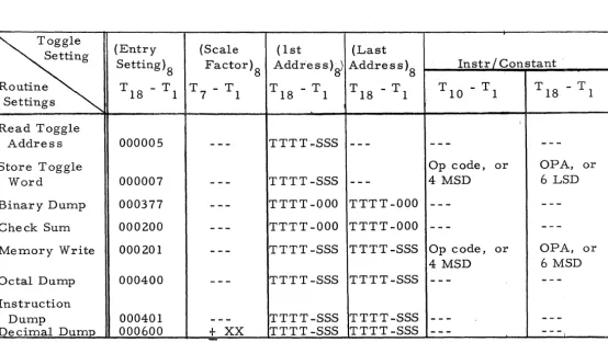
SUMMARY OF BASIC UTILITY ROUTINE ENTRIES
The operator can enter any of the above routines by making the
appropi~iatetoggle setting, then pressing START. In all cases the computer will HALT
and the operator then will make several additional toggle switch settings to
define the various program parameters. The following table summarizes
all the toggle settings necessary to use the Basic Utility Routines. The
individual programs automatically select the necessary Flex punch/print
conditions.
Toggle
(Entry
(Scale
(1 st
(Last
Setting
Setting)8
Factor)8 Address:)g) Address)8
Instr / Constant
Routine
T 18 - T 1 T 7 - T 1
T 18 - T 1
T 18 - T 1
T 10 - T 1
T 18 - T 1
Settings
Read Toggle
Address
Store Toggle
Word
Binary Dump
Check Sum
Memory Write
Octal Dump
Instruction
Dump
Decimal Dump
:
000005
-
--
TTTT .... SSS
-
--
-
--
-
--Op code, or
OPA,
000007
-
--
TTTT-SSS
-
--
4 MSD
6 LSD
000377
-
--
TTTT-OOO TTTT-OOO
-
--
-
--000200
-
--
TTTT-OOO TTTT-OOO
-
--
-
--000201
-
--
TTTT-SSS TTTT-SSS Op code, or
OPA,
4 MSD
6 MSD
000400
-
--
TTTT-SSS TTTT-SSS
-
--
-
--000401
-
--
TTTT-SSS TTTT-SSS
-
--
-
--000600
+
XX
TTTT-SSS TTTT-SSS
---
-
--NOTE:
To use this table, make each toggle setting indicated in the
order listed.
Columns showing dashe s are to be igpored.
Example:
To print out the contents, in decimal format, of the 10 consecutive words
located from 125-000 to 125-011, each word scaled 2-
9
,
the following steps
are required:
( 1 )
( 2)
(3)
(4)
( 5)
( 6)
( 7)
(8)
Set toggles to 000600
Push START button
Set toggles to 000111
Push RESUME button
Set toggles to 125-000
Push RESUME button
Set toggles to 125-011
Push RESUME button
Note that bits 7-1 read, in binary, 1001001. Bit 7 designates "negative";
bits 6-1 designate the decimal number "9".
or
FAST ACCESS TRA.CK CORRESPONDENCE CHART
t
1\060
061
062
063
I~ ;!'
; ' \ I \
TRACKS
i
0~~1062
063
060
I
I \, ; i
I
06~\
I
063
060
i061
I
I
1
063
\
060
'061
i
062
!
I ;
!
000
~
I
I
\
040
100
i
140