I
(
1
(
\"
I
!,
, '
I
I ,
Toe 4100 SERIES
-I 'REFERENCE MANUAL
.' .
(
TOC 4100 SERIES
REFERENCE MANUAL
TANDBERG DATA
AJS
Data Storage Division
P.O. Box 9 Korsvoll
N-0808 OSLO
8,
NORWAY Phone+472189090 Telefox + 472 189550 Telex 74606 tdoto n© Tandberg Data A/S
Port No. 42 21 24 Rev. 01.0 Publ. No. 6ClJ9-1 June 1991
I
i "I
J ! ,!i
i'l
!
i
i'
I:
Related publications available from our Sales Department:
Publ. No. Port No. 5877 426727
5878 426730
Tdle
IDC 3800 SCSI- 1
Interface-Functional Specifications
IDC 3800 SCSI2 Interface
-Functional Specifications
This publication may describe designs for which patents are granted or pending. By publishing this information, Tandberg Data A/S conveys no license under any patent or any other rights.
Every effort has been made to avoid errors in text and diagrams. However, Tandberg Data A/S assumes no responsibility for any errors which may appear In this publication.
It is the policy of Tandberg Data A/S to improve products as new techniques and components become available. Tandberg Data A/S therefore reserves the right to change specifications at any time.
Tandberg Data Table Of Contents
4.
Mounling Specifications4-'
4.1. General Mounting Information 4-7 4.2. Strap Seffing/Selecting Drive Number 4-3.
4.2.1. Selecting Drive Number 4-3 / /
4.2.2. Enable/Disable Bus Parity Checking 4-4 4.2.3. External SCSI-bus Termination 4-4 4.2.4. Serial In/Out Communication 4-5
4.2.5. Test Functions 4-5
4.3. SCSI-Bus Interface Configuration 4-6
4.4. Heat Dissipation 4-7
5. Data Reliability 5-1
5.7. Summary 5-1
5.2. General Introduction 5-1
5.3. WrfteMode 5-2
5.4. Read Mode 5-3
5.5. Cartridge Conditioning 5-5
6. Track, Tape-format and Encoding Speciffcalions 6-1
6.1. Summary 6-1
6.2. Track Specifications 6-2
6.3. Track Format 6-6
6.3.7. Q/C-525 and Q/C-7000 6-6
6.3.2. Q/C-24, Q/C-120and Q/C-150 6-6
6.4. Block Layout 6-7
6.4.7. Q/C-525 and Q/C-700J 6-7
6.4.1.1. Preamble 6-7
6.4.1.2. Block Marker 6-7
6.4.1.3. Data 6-8
6.4.1.4. Control Field 6-8
6.4.1.5. CRC (Cyclic Redundancy Check) 6-10
6.4.1.6. Postamble 6-10
6.4.2. Q/C-24, Q/C-120 and Q/C-150 6-17
6.4.2.1. Preamble 6-17
6.4.2.2. Block Marker 6-12
6.4.2.3. Data 6-12
6.4.2.4. Block Address 6-13
6.4.2.5. CRC (Cyclic Redundancy Check) 6-14
6.4.2.6. Postamble 6-14
6.5. Recording Method 6-15
6.6. Data Encoding 6-15
6.7. Recording Sequence 6-16
6.8. Rewriting of Blocks 6-17
6.9. Filemark and Setmark Blocks 6-18
6.10. Gaps 6-78
6.17. Reference Burst 6-78
6.12. Termination after Underrun 6-78
6.13. Data Append 6-19
6.14. Recording of Even Numbered Tracks 6-19 6.15. Recording of Odd Numbered Tracks 6-79
!
7. Basic Operational Functions 7-1
I,
(
7.1. Reference Tracks 7-7 I:, I:i7.1.7. Write Reference Track
a
7-7if
7.7.2. Read Reference Tracks 7-2
7.2. Write Data and Fl/emarks 7-3
7.2.7. Write From Beginning of Tape 7-3
7.2.2. Write From a Position on the Tape 7-3
7.2.3. Overwrffing Previous Data 7-4
7.2.4. Terminate Write From a Position on the Tape 7-4
7.2.5. Terminate Write at Physical End Of Tape 7-5
7.2.6. Terminate Write at Physical End Of Tape
-Executing the Copy Command 7-5
7.2.7. Recoverable Write E"or (Rewrite) 7-6
7.2.8. Unrecoverable Write E"or 7-7
7.3. Read Data and Filemarks/Setmarks 7-7
7.3.7. Read From Beginning of Tape 7-7
7.3.2. Read From a Position on the Tape 7-7
7.3.3. Read Until Logical End Of Tape 7-7
7.3.4. Read Until Physical End Of Tape 7-8
7.3.5. Read Until Physical End Of Tape
-Executing the Copy Command 7-8
7.3.6. Recoverable Read Error (Reread) 7-8
7.3.7. Unrecoverable Read Error 7-8
8. Hardware Interface 8-1
8.7. Power Interface 8-1
8.2. Introduction to the Signal Interface 8-1
8.3. Definition of Terms 8-7
('
8.4. Electrical Interface 8-2\ ,
8.4.1. Drive Interface Connector Layout 8-3
8.4.2. BusS/gnats 8-4
8.5. Bus Phases 8-5
8.5.7. Bus Free Phase 8-5
8.5.2. Arbitration Phase (Optional) 8-5
8.5.3. Selection Phase 8-6
8.5.4. Reselection Phase (Optional) 8-7
8.5.5. Command Phase 8-8
8.5.6. Data Exchange Phase 8-9
8.5.7. Status Phase 8-10
8.5.8. Message In Phase 8-17
8.5.9. Message Out Phase 8-72
8.5.10. Summary of SCSI-bus Phases 8-13
8.6. Bus Conditions 8-14
8.6.1. Attention Condition 8-14
8.6.2. Unit Attention Condition 8-14
8.6.3. Reset Condition 8-14
8.6.4. Phase Sequencing 8-75
(
' "Tandberg Data Table Of Contents
9. Software Interface 9-1
"
9.7. General Information 9-7
9.7.7. Introduction of QlC-7000 Density Code /
and DC9700 Tape Cartridge Type In the
Mode Select and Mode Sense Commands 9-2
9.7.1.7. SCSI-7. Section 72.3.2. Block Descriptor List
(Mode Select) 9-2
9.7.1.2. SCSI-1, Section 73.3. 7. Header List (Mode Sense) 9-2
9.7.1.3. SCSI-1, Section 73.3.2. Block Descriptor List
(Mode Sense) 9-2
9.1.7.4. SCSI-2, Section 75.3.2. Block DeSCriptor List
(Mode Select) 9-3
9.1.7.5. SCSI-2. Section 16.3. 1. Header List (Mode Sense) 9-3
9.1.7.3. SCSI-2, Section 16.3.2. Block DeSCriptor List
(Mode Sense) 9-3
9.7.2. Introduction of 53 and 80 Ips Tape Speed in the
Mode Select and Mode Sense Commands 9-4
9.1.2.1. SCSI-I. Section 12.3. 1. Header List
(Mode Select) and SCSI-2, Section 15.3.1.
Header List (Mode Select) 9-4
9.7.2.2. SCSI-1, Section 73.3. 1. Header List
(Mode Sense) and SCSI-2. Section 16.3.1.
Header List (Mode Sense) 9-4
9.7.3. Support of Mode 5 in the Write Buffer Command 9-5
10. $e/ftesf and Preventive Maintenance 10-1
10.7. Se/ftests 10-1
10.2. Test Operations 10-1
10.2.1. Power-Up Test 10-1
10.2.2. Reset Test 10-2
10.2.3. Selftest 2 (Customer Incoming Inspection) 10-3
10.2.4. QA Test 10-4
10.2.5. Bum-In Test (For Production Use) 10-4 10.2.6. Drive Acceptance Test (For Production Use) 10-6 10.3. How to Activate the Manual Tests 10-7
70.3.1. Jumper Test Interface 10-7
70.4. Preventive Maintenance 10-8
Appendix A: STM Error Codes A-1
AI. Selftest Error Codes for External Use A-2
A7.7. Group 0: Selftest Errors A-2
A 7.2. Group 1: Tape Read/Write Errors A-2
A 1.3. Group 2: Tape Status Errors A-3
A 1.4. Group 3: Cartridge Related Errors A-3
A2. Se/ftest Error Codes for Internal Use Only A-4
A2.1. Group 4: Gopy Related Errors A-4
A2.2. Group 5: Bus Related Errors A-5
A2.3. Group 6: Acceptance Test Related Errors A-6
A2.4. Group 7: Miscellaneous Errors A-7
(
o.
«TBS»
(-Preface
This is the Reference Manual for the TDC 4100 Series (SCSI compatible) Streaming 114" Tape Cartridge Drive.
Information about some features, options or specifications concerning the TDC 4100 Series Drives are missing or not available at the time of writ-ing (June 1991). In these cases, the abbreviation «TBS .. (To Be Supplied)
is used.
Tandberg Data will appreciate any comments on this publication
regard-ing:
• discrepancies between specification and product
• Inconsistency of definitions
• lack of clarHy In the definitions
• QIC-24, QIC-120, QIC-150, QIC-525 and QIC-1000 compatlbllHy
Tandberg Data Preface
, / '\
This Page Intentionally Left Blank
\
"
(
1.
Chapter 2
Chapter 3
About this Manual
1. 1.
Definitions
The following two terms are widely used throughout this manual:
"The Drive"
Refers to the half-height SCSI ("Small Computer System Interface") com-patible TDC 4100 Series 30-track Drive.
"The Host"
Refers to the host computer that supports the SCSI hardware and software specifications, and thus is able to control the SCSI compatible TDC 4100 Series Drive.
1.2.
Introduction to this Manual
This manual is intended to be the main refer~nce document for users, system programmers and system integrators of the TDC 4100 Series Streaming 114" Tape Cartridge Drive.
The TDC 4100 Series Drive complies with the SCSI Interface Standard, and the QIC-24, QIC-120, QIC-150, QIC-525 and QIC-1OOO Data Inter-change Standards.
The TDC 4100 Series Drive reads and writes thirty tracks serially, running the tape at either 53.3 ips or 80 ips, reads and writes QIC-525 (twenty-six tracks at 120 ips), QIC-150 (eighteen tracks at 96 ips) and QIC-120 (fifteen tracks at 96 ips) and reads QIC-24 (nine tracks, see Section 2.2, running the tape at 96 ips).
Detailed circuit-board block diagrams, schematics and adjustment procedures are not supported by this manual. The field service technician will need the TDC 4100 Series Maintenance Manual and the TDC 4100
Series Recommended Incoming Inspection Procedure in addition to this
reference manual, in order to have the complete service documentation at hand.
describes the basic features of the Drive, accompanied by a block dia-gram.
gives the technical specifications in detail.
Chapter
4
ChapterS
Chapter 6
Chapter 7
ChapterS
Chapter
9
Chapter
JO
Tandberg Data About This Manual
contains mounting specifiCations.
describes data reliability and tape conditioning.
describes the tape formats (9, 15, 18, 26 and 30 tracks) and how the data is encoded.
describes the Drive's supported basic operational functions.
describes the interface of the Drive with regards to the hardware.
this section describes the major differences and special features related to the TDC 4100 Drives which are not included in the TDC 3800 SCSI-1
and TDC 3800 SCSI-2 Interface - Functional Specifications.
gives descriptions of the Drive's extensive built-in selftest possibilities and how to perform proper preventive maintenance.
1.3. Additional Documentation
The QIC-24 and QIC-02 Standards, Revision D,
(Part No. 402732, Publ. No. 5447), available from our Sales Department.
The QIC-120 Standard for Data Interchange, Revision E, April 1991
The QIC-150 Standard for Data Interchange, Revision J, April 1991
The QIC-525 Standard for Data Interchange, Revision E, April 1991
The QIC-1OOO Standard for Data Interchange, Revision C, April 1991
1-2 TOC 4100 Reference Manual
(
2.
QIC-1ooo - 30 tracks
QIC-525 - 26 tracks
QIC-150 - 18 tracks
QIC-120 - 15 tracks
QIC-24 - 9-tracks
Introduction to the Drive
2.1. Summary
This chapter describes the basic features of the Tandberg Data TDC 4100 Series Streaming Tape Cartridge Drive. After a general introduction, a description of the mechanical and electrical drive design is given.
2.2.
General Drive Description
The Tandberg Data TDC 4100 is a Streaming 114" Tape Cartridge Drive. The TDC 4100 Series Drive reads and writes according to the following table:
Tape Format Capacity Write
QIC-1000 1.0 GByte
x
QIC-525 525 MByte x
QIC-150 155 MByte
x
QIC-120 125 MByte x
QIC-24 60 MByte
Drive Application
The Drive is well suited for a variety of applications:
./ Winchester back-up ./ Archival storage
./ Low cost background mass-storage system ./ Data logging
./ Replacing the floppy disk for data Interchanges ./ Software distribution
Streaming
Read
x
x x x x
The mode of operation is streaming, i.e. the Drive is designed to run the whole length of the tape, normally without any interruption. Un-necessary start and stop operations in the middle of the tapes will slow down the system considerably. Too many starts and stops over a short tape distance may also reduce tape tension, which may adversely affect the recording performance.
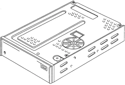
Basic Mechanical Building Blocks
The Drive mechanism is built inside a rigid casting. The mechanism includes a direct-drive, brushless capstan motor, a door-locking and ejection system and a head-moving ("worm-gear") system. Figure 2.1 illustrates the Drive's mechanical outline.
Note that mounting the Drive top or bottom-flush against a flat surface will impede air flow and cause overheating of the capstan motor! This
MUST be avoided!
Tandberg Data Introduction
to
the DriveFigure 2.1 The TDC 4100 Series Drive
the Electronics
The electronics are contained on two printed circuit boards: The Mainboard and the Sensorboard.
The Drive electronics comprises the 68HCn microcomputer, the AlC-6250 SCSI Controller and two custom made Tandberg Data ASICs: one handling the Drive's formatting functions; the other handling the Buffer Controller and the ECC.
(ASIC
=
Application Specific Integrated Circuit).All electronics except the opto-electronic tape hole sensors and the mech-anical "cartridge-in-place" and "write protected" switches are situated on the Mainboard. The exceptions mentioned are located on the Sensor-board.
(
Data Block
n
Preamble Data Marker
i
'"
(
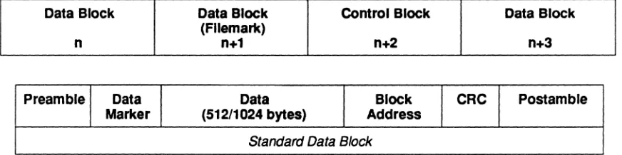
2.3. Tape Format and Drive Operation
Data is formatted into small blocks, each block containing 51211024 bytes of data (1024 bytes
=
QIC-525 or QIC-lOOO). Special address and check-ing bytes are added to each block. The basic layout is shown in Figure 2.2.Data Block Control Block Data Block (Fllemark)
n+1 n+2 n+3
Data Block CRC Postamble
(512/1024 bytes) Address Standard Data Block
Figure 2.2 Track format
Write Operation
The data bytes are transferred from the Host to the Drive and stored in the Drive's data buffer. The data is assembled into blocks of 51211024
bytes. The Drive adds special address and check characters to each block prior to writing the complete block on the tape. The Drive performs read-while-write checking, and blocks with errors are automatically rewritten further down the tape.
Read Operation
In read mode, data is read from the tape and the special address and check characters are removed. The data bytes are then transferred to the Host via the built-in data buffer in the Drive.
Any corrupted data will normally be corrected by the Drive
(QIC-1000/-QIC-525) or the Drive will perform a reread operation (QIC-241120/150).
Edge/Reference Track Seeking
In order to improve the track-location accuracy and to ensure data interchangeability between cartridges, the Drive uses the edge of the tape as the basic reference during write mode and the Reference Bursts
as references during read operations. When changing tracks the head will always do a final movement upwards to reach the new track location. This is done to eliminate influence of backlash in the worm-gear.
Edge Seeking in Write Mode
See Chapter 7. Basic Operational Functions.
Track Seeking in Read Mode
See Chapter 7. Basic Operational Functions.
I
MCU
Tandberg Data Introduction to the Drive
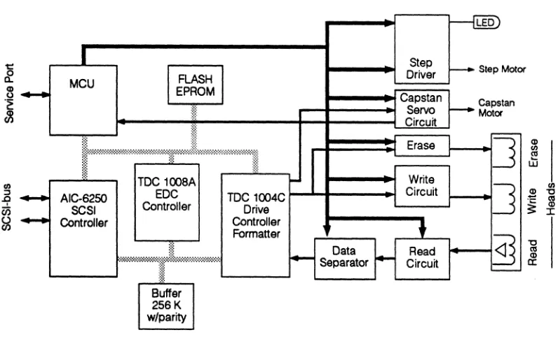
2.4.
Drive Block Diagram with Description
All drive operations are controlled by the 6SHeU microcomputer on the Mainboard. This includes the stepping and positioning of the head, the capstan motor operation, the sensing of the tape holes and the communication with the Host.
Figure 2.3 below shows a block diagram of the Drive.
~
~
f'
Step Driver Capstan Servo Circuitr---rw
r----
Step MotorCapstan Motor
Erase
J
Q)I
Ul
~
Write
~
TOC 1008A... AIC-6250 SCSI Controller
EDC Controller
-TOC 1004C t--... +---~
Drive Controller Formatter Circuit
t
Read CircuitFigure 2.3 Drive block diagram
Capstan Motor System
]
Ul~
"Ctil
Q) :r:
@]
L...--The capstan motor speed is controlled by an analog servo and monitored
by the processor. Pulse modulation of the motor voltage is used in order
to reduce power dissipation in the motor drive electronics.
Head Positioning System
The head is moved up and down with a double-screw {"worm-gear"} system, controlled by a stepper motor. The microcomputer supplies the pulses to the stepper motor. The microcomputer is also able to detect either the edge of the tape or the edge of the reference signals by employing the tape edge sensor electronics.
2-4 TOC 4700 Reference Manual
,/
/
(
(
'D'Ie Write/Read/Erase Head
The head has two recording channels designed for serpentine recording. Each channel contains a write and a read section. When writing, the Drive runs a read-while-write check to verify the recorded data. The head also has a full-width erase bar that erases all the tracks on the tape each time the Drive starts writing from Track O.
Sensor System
The EOT (End of Tape), the BOT (Beginning of Tape), the LP (Load Point), the EW (Early Warning) and the Tape ID holes in the tape are detected by the Mainboard microprocessor using the Tape Hole Sensor circuit. The detection system includes a sophisticated, synchronously clocked hardware system to avoid malfunction and tape run-out.
'D'Ie Write Circuit
This circuit performs the actual writing on the tape. Information about the data to be written is received from the Write Sequencer.
The write circuit adapts itself to the type of tape used.
During the read/write operation, the Write current is automatically ad-justed to match the actual kind of tape and format written
NOTE:
Use only DC9100 tape cartridges or equivalent when writing QIC-l000 tape format. Use DC6320 or DC6525 type tape cartridges only when writing QIC-525 tape format. When writing QIC-120 and QIC-150, DC6150 tapes or equal should be used.
'D'Ie Read Circuit
The Read Circuit detects each flux transition from the read head and converts it to a digital pulse. Automatic Gain Control (AGC) is used to reduce the effect of the output variations from one cartridge to another. The Read Gain is automatically set to match the actual performance of each cartridge.
'D'Ie Data Separator
This circuit generates the Read Clock and the Read Data pulses. A phase locked loop is used to track the Instantaneous Speed Variation (ISV) of the tape.
'D'Ie MicroComputer Unit
The MCU controls and drives the operation seen from the user interfaces.
The microprocessor uses its data and address-bus to communicate with the digital circuit, and the SPI (Synchronous Pheripheral Interface) to some of the logical circuits.
Tandberg Data Introduction to the Drive
The SCSI Controller
The SCSI Controller handles both the SCSI control functions and the bus-drivers and receivers.
All the SCSI Contl'Oller-circuitry is held inside the same chip, the AlC· 6250 circuit.
Error Correction (ECC) and DMA Controller
This is a Tandberg Data ASIC (TDC l008A) controlling the buffer and the DMA·channels between the digital control circuits. It also handles the error correction code (ECC).
The Tape Controller
This is a Tandberg Data ASIC (TDC lO04C) controlling the Read and Write encoding/decoding between the data·buffer and the read/write circuits.
2.5.
Interface to Host
The interface to the Host conforms with the SCSI·l and SCSI·2 stan-dards. Communication between the Drive and the host system is under· taken via a 9·bit bidirectional bus and nine bidirectional control lines. The Drive accepts commands from the Host. The Host may read the Drive status by asking for the transfer of special status bytes from the Drive. See Chapter 9 for a complete list of available commands. During read and write operations, the data bytes are transferred via the Host Bus. The transfer of each data byte is supervised by the control lines in a handshake operation to minimize timing burden on the host controller. For a detailed description of the hardware and software interface to the Host, see Chapters 8 and 9.
(
(
3.
Standard drive moun"ng
Max. dimensions
Weight
Typical
Maximum
+5V
Product Specifications
This section contains a comprehensive set of specifications for the Drive.
3. 1. Mechanical Dimensions and Weight
Fits in 5 114" half-height ("slim-line") enclosure for diskette or disk drive. Standard mounting holes fOT a half-height drive.
44 x 150 x 218 mm (1.732" x 5.905" x 8.583")
1.1 kg (2.4 lbs)
See Section 4.1 fOT mounting details and mechanical drawings.
3.2. Power Requirements
Sleep Motor Motor Running 120 Ips
Active Start-Up Write/Erase
+12V +5V +12V +5V +12V
SOOmA 80mA SOOmA 2.0A SOOmA 0.9A
700mA 100 mA 700mA 3.3A 700mA 1.4SA
Current (A)
3-1
1.0 1 - - - + - - l I I I f +
0.8 I---+---tt-.
0.6 I---+-+lilf---+--"-lilil
0.4 I----t-+-~--+---t--+--~_+-__+_-_t____I
0.2
J;:::::;;+;:Ii-'I-III-111
0.0 1---+--+---+--+----1--+---+--+----+---1
o
100 200 300 400Time (ms)
Typical current curve for the +12 V power supply during capstan-motor start-up (80 ips)
TOC 4700 Reference Manual
:1 Ii.
VoHage variaHons
Ripple on +5 V and+12V
Power dissipation
OperaHng
Storage
Transport
Relative
humidity (%)
80
20
Tandberg Data Product~ecmcatJons
Including ripple +5V± 5%
+12V ±10% Including ripple (No restrictions on the turn-on
sequence) Maximum 200 mV Peak-to-Peak
3.SW I5.0W
Motor not running
Typical, motor running with cartridge inserted
3.3.
Environmental Specifications
The following definitions are used in this section: The unit is unpacked and power is turned on. The unit is unpacked and power is turned off.
The unit is packed in original package as when ready for shipment from factory.
3.3. 1.
Temperature and Relative Humidify
Mode Temperature (OC) Rei. Humidity (0/0)
Operating * +5
-
+45 20 - 80Storage -30
-
+60 10 - 90Transport -30
-
+60 10 - 90*
In operating mode these figures are limited by the media. Due toadditional heating coming from internal friction in the cartridge, the maximum surrounding temperature should not exceed 40°C in order not to violate the maximum temperature rating for the tape cartridges which is 45°C. Maximum Wet Bulb temperature is 26°C operating. (See figure below and IMPORTANT-notice in Chapter 5. Data Reliability).
5 30 45 Temp. (OC)
Drive temperature and humidity limits, operating
3-2 TOC 4100 Reference Manual
(
Operating
Operating Storage Transport
Test method
I
Mode OperatingStorage
Transport
Topple Storage
Shock Transport
Shock Storage
Shock Operating
3.3.2. Temperature Variation
Maximum 10°C per hour, non-condensing
3.3.3. Atmospheric Pressure
53 - 106 kpa [maximum altitude 4000 m (13 000 ft)]
15 - 106 kpa [maximum altitude 13 000 m (40 000 ft)]
15 - 106 kpa [maximum altitude 13 000 m (40 000 ft)]
3.3.4. Vibration
EC-68-2-6
Frequency Peak Displacement Acceleration
5 - 60 Hz 0.035 mm ±1 0 %
-60 - SOO Hz
-
O.SGS - S8 Hz 0.1S0mm±10%
-58 - SOO Hz
-
2.0GS - 12 Hz 3.S mm±10%
-12 - SOO Hz
-
2.0G3.3.5. Impact and Shock
Lifted 50 mm and allowed to fall on to each of the four bottom edges and comers. (Horizontal position see section 4.1). (IEC-68-2-31).
Lifted 1.0 m for "single-pack" and 0.6 m for "10-pack", and allowed to fall freely on to a hard, rigid surface Fall sequence includes all 6 sides and the most critical edge and comer. (IEC-68-2-32).
392 m1s2 (40 g), Halfsinewave, 11 ms duration. (lEC-68-2-27).
98 m1s2 (10 g), Half sinewave, 11 ms duration.
3-3 IDe 4100 Reference Manual _
I ~
I'
i!
Tandberg Data Product Specifications
3.4. Product Performance Specifications
3.4.1. Audible Noise
55 dB (A). Integrated over 60 seconds, the Drive operating at 120 ips on an average cartridge. Measured at a distance of 1 m in all axes, the Drive standing free, using a cartridge with nominal noise level. Worst-case cartridges may increase this figure. When the tape and the head stepper motor are not running - none of the components in the Drive are generating any audible noise.
3.4.2. Radiated Electromagnetic Interference
The Drive complies with FCC Rules Part 15 Subpart B Class B, VDE 0871 Class B and EN550221CISPR 22.
3.4.3. Susceptibility to Electromagnetic Interference
An electromagnetic field of 6 Vim will not cause any functional
distur-bance. (lEC 801-3).
3.4.4. Susceptibility to Electrostatic Discharges
The Electrostatic Discharge specification is referred to:
A: Closed front door and other parts of the Drive that are accessible from the front when the Drive is mounted in a cabinet - operating in
any mode. Air gap discharge. Specification method: IEC 801-2,
discharge network of 150 pF and 330
n,
or 150 pF and 150n.
The Drive will not have any hard errors at - or below 12 kV. No physical hardware errors will occur at - or below 25 kV.B: Open front door, metal body discharge to a testpoint approximately 1 cm on the inside, the Drive in idle mode. Simulator: Schaffner NSG 432 with "Real ESD Adapter", complies approximately with ECMATRl40.
The Drive will not have any hard errors at - or below 4 200 V. The Drive will operate properly when the door is closed.
3.4.5. Safety Standard
The Drive complies with EN60950lIEC 950, VDE 0805, UL 1950 and CSA C22.2 - 950M 1989.
3.4.6. Mean Time to Repair
The Drive has a MTTR of less than 0.5 hrs. The MTTR is based on ex-change of complete module assemblies. The head assembly can be exchanged in the field without the use of special alignment tools.
(
Predicted, Actual "Mature" MTBF
Head Life Time
Motor Life Time
Door Open/Close
3.5.
Product Reliability
The predicted reliability of the Drive must be expressed in two parts that will cover the expected random Mean Time Between Failures (MTBF) for the electronics based on the Power On Hours (POH) and the Mean Time to Failure (MTTF) for the mechanical parts based on the POH and the
Duty Cycle.
3.5. 1.
Electronics MTBFThe predicted MTBF has been calculated using a conservative Parts Count Model based on data from MIL-STD-217E. This gives a value for the "mature" MTBF for POH of 20.000 hours.
The expected Early Life Failures can be estimated by reducing the MTBF by a factor of 3 (three) for 0 - 500 POH and by 2 (two) for 500 - 1.000 POH.
> 80.000POH
The actual "mature" MTBF for the electronics part, based on field experi-ence of similar equipment, is expected to be a factor of between 4 and 5 times higher than that predicted by the model. This means that the MTBF will most probably lie in the range 80.000 POH and upwards. It is not possible to be more precise with these predictions, as the actual conditions under which the Drive is used is not under Tandberg Data's control and may vary significantly from one customer to another.
Important Notice!
The MTBF value is dependent of correct handling (f. ex.: ESD protective measures are used), installation and use of the Drive
by the system installer/designer.
3.5.2. Mechanics MTTF
The failure rate for these parts is related to how often the Drive is actually used. In the case of the most critical components which are the head and the capstan motor, the reliability is specified as the Mean Time to Failure (MTl'F) based on the POH and the Duty Cycle. The MTTR-values are not accumulative as the wear takes place in parallel.
> 5.000 POH at 100 % Duty Cycle (see NOTES 1 and 2)
> 50.000 POH at 10 % Duty Cycle (see NOTES 1 and 2)
> 10.000 POH at 100 % Duty Cycle (see NOTE 2)
> 100.000 POH at 10 % Duty Cycle (see NOTE 2)
> 15.000 open/close cycles
NOTE 1:
This figure is based on using DC9100 tapes. See also Section 3.6.3. and
Important notice in Chapter 5. Data Reliability!
NOTE 2:
Streaming operation, NOT extensive start/stop operations.
Useful ute Cycle
Tandberg Data Product Specffications
3.5.3. Useful Ute Cycle
This is the period during which the Drive is serviceable either by adjust-ment 01' replacement of defective parts. In the case of the mechanical
parts, replacements must be expected as soon as the life-time is approached (see 3.5.2). This will depend on the actual usage of the Drive
in each case.
> 10 years
3.5.4. Total Drive RelIabIlIty
Two different and independent failure mechanisms determine the failure frequency of the total Drive. These are related to the MTBF of the electronic parts alone (80.000 POR) and the limits set by the capstan motor and the magnetic head which are the most significant wear-out components.
Thus, for the total Drive, the duty cycle of tape motion versus the total amount of Power On Rours (POR) will determine the point in the life cycle where the End-Of-Life situation for a wear component is reached. Operating the Drive inside the stable part of the so-called "bath-tub curve" - the table below illustrates the effect of the failure mechanisms:
I
Duty Cycle (%)I
MTBF (hrs)I
POH Upper Limit for the MTBF (hrs)10 80.000 100.000
15 80.000 67.000
20 80.000 50.000
50 80.000 20.000
(
Suggested typesot media Number of recorded tracks Track width I I II
I I.
I.
3.6. Functional Specifications
3.6.1. Media
3MDC6150 3M DC6320 3MDC6525 3MDC9100
183 m (600-foot), cert. for 12 500 frpi 183 m (600-foot), cert. for 20 000 frpi 311 m (1020-foot), cert. for 20 000 frpi 232 m (760-foot), cert. for 45 000 frpi
... or equivalent tapes from other manufacturers.
NOTE:
See Important notice in Chapter 5. Data Reliability about tape/envir-onmental temperature and humidity restrictions.
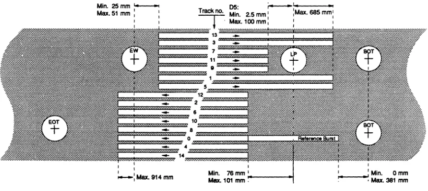
3.6.2. Track Width and Location
QIC-24: QIC-120: QIC-150: QIC-525: QIC-1000: QIC-24: QIC-120/150: QIC-525: QIC-1000:
Nine tracks - read only! Fifteen tracks
Eighteen tracks Twenty-six tracks Thirty tracks
0.343 mm ±0.013 mm (0.0135" ±0.0005") 0.165 mm ±0.013 mm (0.0065" ±0.0005") 0.1778 mm +0.0000/-0.0127 mm
(0.0070" +0.0000"/-0.0005") 0.1778 mm ±0.00381 mm (0.0070" ±0.00015")
Track locations (NOT drawn to the same scale!) are shown below and on
the following pages:
TrackS Track 1 Track 7
J
1
1
Track 3
Track 4 L1 LS
Track 0
Track 6
.'_ +
L4 L3~
Track 2 ..I ;
~6
iO
+
!
TrackSI
LEe~
La L2RoI.r ... Plan.
~
1
Reference EdgTrack locations for the QIC·24, 9-track tape format
3-7 TOG 4100 Reference Manual
i "
! ,~
i '
Tandberg Data Praduct~ecmcations
\ 0 0
Track 13 .
I 0 I
I
Track 3
I I Track 7 ..
! !
Track 11
j j Track 9 .. ..
1
I I
Track 1 '. I I Track 5
1
L3 L1I I Track
12 ..
Lt
1
L11 L7
I i Track 2 .. ... ! ! Track 6
~
1
)
i 0 Track 10 .',~
• !
!
I I Track 8
+
I us L10 ,
(
I Track 0 ...L4 d4
t!o
! I
~
Track 4!
Track 14 .... .. r
3
I I
LE
' - -
Reference EdgeTrack locations for the QIC-I20, I5-track tape format
I i Track 13
! I Track 15 ' .. ...
I Track 5 ... ....
1
i I Track 1
I
Track 3 ....
I I Track 11 ...
! !
Track 7 ....
1J
i i Track 9 .... , .... ' .. " ...
.t
J, }
L15 L1
I I Track 17 .'
L1 L5
i I Track 12 .,' L3
I ! Track 2 ..
Track 6
ot., Lk
1
I i Track 10 . . .. . ...
Lr
J
! !
Track 8 '" .. .8 L10 L,S
l
j i Track 0" ,. ...
I I Track 4 .. ' " " 4
Ll4 Lf6 Lt
.
I I
J
Track 14 "-.
I ! Track 16 ., .
..
,•
3
I lE ' - - Reference Ed e
9
i I Track 21
J1
I I Track 9 . "
I I Track 17 "
Lh
~g
! ! Track 5 ., . "
Track 13 ... l13r l5 ~f
~
i i Track 1 ...
I I
115i
Ltg
&
J"
J5RTrack 15 L3
; I Track 3
I !
Track 19 j
•
l23I i Track 7 ...
~
!
!
! I Track 23
0 Track 11
L1
I Track 25
I
1
Track 20 . ..
1
I Track 8 ...
!
~
Track 16 ..
j Track 4 ... l~6 ~J
I
Track 12 , .. 112r L4 t ~
I Track 0
l14.L
l~8
~
~
J4
I Track 14 l2
Track 2 I
•
I
Track 18
t
If
! '.
J
Track 6 .. '
-1
r
i i Track 22
I I
l
Track 10 ' .. I I Track 24 ..I
LE
' - -
Reference EdgeTrack locations for the QIC-525, 26-track tape format
(
i
i I
! !
i I
I !
.
i ! II I
! ! i i
I I
I
.
I! I
I I
! !
i i
I I
I I
! !
i I
I !
.
I iI I
I I
!
! i
Track Z7
1
Track 13 ...J3 Track 23
l
Track 9
19
Track 19
Track 5 L19
Track 15 L15T L5
•
1
1
Track 1
Track 17 L171. L3
J;
&
1
Track 3 ...
+
Track 21
1
L111
1
l29RTrack 7 ..
J
Track 25 Track 11
Track 29· . . ...
IF
Track 26
1
11Track 12 Track 22
Lk
l2
Track 8la
1
Track 18
Track 4 L18
Track 14 L14T_ L4 -~
J.
T
Track 0116...L
..t
l
J4Track 16 L2
Track 2
J.
Track 20
J.
!
T
T
Track 6 LO
1
Track 24 ... . ...1
Track 10 , Track 28
LE ' - - Reference E dg e
Track locations for the QIC-lOOO, 30-track tape format
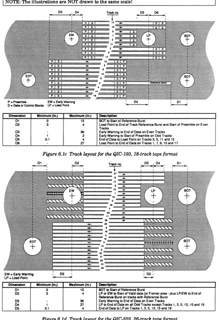
NOTE:
A tape partitioned for Quick File Access (QFA) shall have Track 29 re-corded in the forward direction, without any Reference Burst. See Figure 6.le.
Tandberg Data Product Specifications
The dimensions are as follows:
QIC-24 QIC-l50 QIC-525 QIC-l000
LE 1.778mrn LE 1.778 mrn LE 1.778 mrn LE 1.778 mrn LE 1.778mm (0.070" ) (0.070"' ) (0.070"') (0.07a') (0.070" )
LO 2.50 mrn %0.107 mm LO 1.092 mrn ±C.076 11m LO 1.255 mrn ±C.076 mrn LO 1.803 11m ±C.OSI mm LO 1.5799 mm ±C.0368 mrn (0.102" ±C.0042") (0.Q43" ±C.OO2') (0.04114' ±C.OO3") (0.0710" ±C.0020") (0.0622" ±0.00145; LI 5.03 mrn ±C.l07 mm LI 2.845mm±C.OSl mm LI 3.740 mm ±C.OSI mrn LI 3.061 mm ±C.OSI mm LI 3.0658 11m ±0.0508 mm
(0.198" ±C.0042j (0.112" ±0.002') (0.1472" ±C.OO2') (0.1205" ±C.0020j (0.1207" ±0.0020") L2 1.37 mm ±0.107 mm L2 1.826 mrn ±C.OSI mrn L2 1.380 11m ±C.OSI 11m L2 0.4S7 mm 10.033 mm L2 -0.3962 mm ±C.0368 mm
(0.054" ±C.0042j (0.064" ±C.002") (0.0535' ±C.OO2') (0.0180" ±C.0013j • (0.0156" ±C.00145") L3 3.81 11m ±o'107 mrn L3 4.470 1Im±C.OSl 11m L3 3.400 11m ±C.OSI 11m L3 0.457 mm ±O.033 mm L3 • 0.3962 mm ±C.0368 mm
(0.150" ±C.0042j (0.178" ±C.OO2') (0.13311" ±C.OO2') (0.0180" ±C.0013j • (0.0156" ±C.00145; L4 3.20 mrn ±C. 107 mm L4 0.406 mrn ±C.OSI 11m L4 0.340 11m ±C.OSI 11m L4 0.457 11m ±C.033 mm L4 0.3962 11m ±C.0368 mm
(0.128" ±C.0042j (0.016" ±C.OO2') (0.0134' ±0.002') (0.0180" ±C.0013j (0.0156" ±0.0014S·) LS S.1I4 mrn±C.l07 mm L5 2.438 mrn ±C.OSI mrn L5 4.080mm±C.OSl mrn L5 0.457 mrn ±C.033 11m LS 0.3962 mrn±O.0368 mm
(0.222" ±C.0042j (0.098" ±O.OO2') (0.1806" ±C.ClO2") (0.0180" ±C.OOI3") (0.0156" ±0.00145·)
L8 1.88 mrn ±C.l07 mrn L6 1.2111 mrn ±C.OSI mm L6 1.020 1Im±C.OSl mrn L8 0.1114 mrn ±C.033 mm L6 -0.7925 mm ±C.0368 mm (0.078" ±C.0042j (0.048" ±C.002") (0.0402" ±C.OO2') (0.0380" ±C.0013") • (0.0312" ±O.00145") L7 4.42 11m ±C.l07 mm L7 4.084 mrn ±C.OSI mrn L7 2.720 mm±C.OSl mrn L7 0.1114 mm ±C.033 mm L7 -0.7925 mrn ±C.0368 mm
(0.174' ±C.0042j (0.180" ±C.OO2') (0.1071' ±C.OO2') (0.0380" ±C.0013j • (0.0312" ±C.00145; L8 0.76 mm±C.l07 mm) L8 D.408 mrn ±C.OSI mm L6 0.340 rnm ±C.OSI mm L8 0.1114 mm ±C.033 mm L8 0.7925 mm ±0.0368 mm
(0.030" ±C.0042") (0.016' ±O.OO2') (0.0134' ±0.002j (0.0380" ±C.0013j (0.0312" ±C.0014S·)
LSI 3.251 mm±C.OSl mm LSI 2.380 11m ±C.OSI mm LII 0.1114 mm ±C.033 mm LII 0.7925 mm±O.0368 mm (0.128" ±O.OO2j (O.09CI7" ±C.002") (0.0380" ±C.0013") (0.0312" ±C.00145·) Ll0 0.813mm±C.OSl mm Ll0 D.680mm±C.OSl mm Ll0 1.372 11m ±0.033 mm Ll0 1.1887 mm 10.0368 mm
(0.032" ±C.002j (0.0288" ±C.002") (0.0540" ±C.0013") (0.0488" :1:0.00145') Lll 3.858 mm ±C.OSI 11m Lll 3.060 mm±C.OSl mrn Ll1 1.372 mm ±C.033 mm Lll 1.1887 mm±C.0368 mm
(0.144' ±C.002j (0.1205" ±C.OO2") (0.0540" 10.0013") (0.0488" 10.00145; L12 2.032 mm ±C.051 mm L12 1.700mm±C.OS111m LI2 0.229 mm 10.033 mm L12 1.1887 1Im±C.0388 mm
(O.Cl8O" ±C.002") (0.0669" 10.002") (0.0090" ±C.0013") (0.0488' ±C.00145·) L13 4.877 11m ±C.OSI rnm L13 4.760 11m ±C.OSI 11m L13 0.229 11m 10.033 mm LI3 1.1887 mm 10.0388 mrn
(0.192" ±D.OO2') (0.1874' 10.002") (0.0090" 10.0013") (0.0488' 10.0014S; L14 0.813mm±C.OSl mm L14 0.680 mm ±C.OSI 11m L14 0.229 mm 10.033 mm L14 0.1981 rnm ±0.0368 mm
(0.032" ±0.002") (0.0288" 10.002") (0.0090" 10.00131 (0.0078" 10.00145; LIS 4.420 mm ±C.OSI mm LIS 0.229 mm ±C.033 mm LIS 0.1981 mm±O.0368mm
(0.1740" ±C.OO2") (0.0090" 10.0013") (0.0078" 10.0014S·) L16 1.020 mm ±o.OSI mm L16 0.688 mm ±D.033 mm L16 • 0.1981 mm ±C.0368 mm
(0.0402" ±C.002") (0.027a' ±C.0013") • (0.0076" ±C.00145") L17 2.040rnm±C.OSl mm L17 0.688 mm ±D.033 mm L17 -0.1981 mm±C.0388mm
(0.0803" ±C.002") (0.027a' ±C.0013") • (0.0078' ±C.DOI45j L18 0.688 mrn ±0.033 mm L18 0.5044 mrn ±D.0368 mm
(0.027a' ±C.IlOI3") (0.0234" :to.00145") Ll11 0.886 mrn ±0.033 rnm Ll11 0.5044 mm±C.0388 mm
(0.027a' ±C.00131 (0.0234" ±C.00145;
L20 1.143mm±0.033mm L20 -0.5944 mm ±C.0368 mm (0.0450" ±C.00131 • (0.0234' ±D.00145") L21 1.I43mm±O.033mrn L21 -0.5044 mm ±C.0368 mm
(0.0450" ±C.0013") • (0.0234' ±0.00145;
L22 1.143 mm ± 0.033 mm L22 0.9906 mrn ±0.0368 mm (0.0450" ±C.00131 (0.0390" ±C.00145;
L23 1.I43mm± 0.033 mm L23 0.9906 11m ±C.0388 mm (0.0450" ±C.0013j (0.0390" ±C.00145·) 1.24 1.600 mm ±0.030 mm 1.24 • 0.9906 11m ±C.0388 mm
(0.830" ±C.0013j • (0.0380" ±C.00145") L25R 1.600mm ±C.03O 11m L25 • 0.9906 11m ±C.0368 mm
See NOTE 1 below: 0.830" ±D.0013j • (0.0380" ±D.00145") L25F 1.372 mm ±C.03O mm L28 1.3888 mm±D.0388 mm
(0.540" ±D.0013") (0.0548" ±C.0014S·)
L27 1.3688 mm ±C.0388 mrn (0.0548" ±0.00145") l28 • 1.3988 mm ±C.0368 mm
• (0.0548" ±C.00145; L29R • 1.3888 mm ±C.0368 mm See NOTE 2 below: • (0.0545" ±C.00145;
L29F 1.5850 mm ±O.0388 mm (0.0824' ±O.00145·)
NOTE 1:
Track 25 may be referenced to either Track 1 (L25R,) when recorded in the reverse direction or to Track 0 (L25F) when recorded in forward direction.
NOTE 2:
Track 29 may be referenced to either Track 1 (L29R,) when recorded in the reverse direction or to Track 0 (L29F) when recorded in forward direction.
NOTE "-":
The "." sign indicates that the track is located below its corresponding Reference Track.
Head type
Write track width
Read track width
3.6.3. Head Specifications
2-channel read-after-write for serpentine recording. Full width erase bar. Ferrite cores.
QIC-1000:
QIC-lOOO:
0.1778 mm to.0038 mm (0.007" to.0015")
0.089 mm to.0038 mm (0.0035" ±G.00015")
Erase head Full tape width erase bar. All tracks are erased when writing from BOT on Track O.
Alignment error bet- Maximum 0.0127 mm (0.005")
ween read and write sections
Erase and bias 9.6 MHz
frequency
Azimuth, S 7 minutes-of-arc
Read/Write
Gaplines - not Erase
Zenith, Read/Write < 15 minutes-of-arc
Gaplines - not Erase
Head Ufe
nme
> 5.000 hrs.IMPORTANT!
The head life time specifications stated by Tandberg Data AlS
assumes running tapes in an environment with an average
relative humidity of a minimum of 40 % and a maximum of not
more than 65 %; all at a temperature of not more than +30°C
outside the cartridge.
Relative humidities up to 80 % are assumed only for a maximum
of 1 hour for every 24 hours of tape running. Maximum relative
humidity of the environments shall not be more than 50 %
averaged over the life cycle test, and never more than 65 %,
averaged over 200 running hours.
Relative humidities of less than 40 % are assumed only for a
maximum of 1 hour for every 24 hurs of tape running.
The Head Life Time specifications assumes that tapes are re-placed for every 2 500 passes.
The head life time specifications given for this product is not valid if the drive has been used in environments· or with tapes· that cannot meet the specifications above.
Tandberg Data AlS does not warrant against failure of any tape
drive product that has directly or indirectly been exposed to conditions outside the specifications given above.
Type of operation
Tape speed
Tape speed
variation
Start/stop time
Tape speed
Tandberg Data Product Specifications
3.6.4. Tape Movement
Streaming
QIC-241120/150: QIC-525: QIC-lOOO:
Short term (1 byte): Long term (512 bytes):
[@ 2.03 mls (80 ips)]:
2.44 mls (96 ips) 3.05 mls (120 ips)
1.355 mls (53.33 ips) or 2.03 mls (80 ips)
±6 % with cartridge inserted ±2 % with cartridge inserted
Start time typical: Stop time typical:
200ms 200ms
[@ 1.355 mls (53.33 ips)]: Start time typical: 135ms 175ms
[@ 3.05 mls (120 ips)]: (See figure)
[@ 2.44 mls (96 ips)]:
Stop time typical:
Start time typical: Stop time typical:
Start time typical: Stop time typical:
300ms 280ms
240ms 230ms
120 ips
I---::;,.."t---o
~~~---+---+---+---~~---Start time Stop time
Typical 300 ms Typical 280 ms Time (ms)
Typical curves for tape speed during start I stop operations
3-12 TDC 4100 Reference Manual
(
• Start/stop distance Recording method Recording density Maximum flux density Block size Nominal overhead per block WrHe procedure Read procedure[@ 2.03 m/s (80 ips)]: Start distance typical: 10" Stop distance typical: 7"
[@ 1.355 m/s (53.33 ips)]: Start distance typical: 6" Stop distance typical: 4"
[@ 3.05 m/s (120 ips)]: Start distance typical: 22" Stop distance typical: 15"
[@ 2.44 m/s (96 ips)]: Start distance typical: 15" Stop distance typical: 10"
3.6.5. Ilecording Specifications
NRZ1 (NON-RETURN to ZERO, change on ONEs) with data encoded according to the 0,2 GCR rules.
QIC-24: QIC-120/150: QIC-525: QIC-1000: QIC-24: QIC-120/150: QIC-525: QIC-1000:
315 data bits per mm (8 000 data bits/inch) 394 data bits per mm (10 000 data bits/inch) 630 data bits per mm (16 000 data bits/inch) 1417 data bits per mm (36 000 data bits/inch)
Maximum 394 ftpmm (10 000 ftpi) Maximum 492 ftpmm (12 500 ftpi) Maximum 788 ftpmm (20 000 ftpi) Maximum 1772 ftpmm (45 000 ftpi)
QIC-2411201150: 512 data bytes QIC-52511000: 1024 data bytes
QIC-24:
QIC-120/150:
QIC-525:
QIC-I000
19.5 bytes (Preamble 12, Byte Marker 1, Block Addr. 4, CRC 2 and Postamble 0.5) 23.5 bytes (Preamble 16, Byte Marker 1, Block Addr. 4, CRC 2 and Postamble 0.5) 50 bytes (preamble 40, Byte Marker 1, Block Addr. 4, CRC 4 and Postarnble 1) 59.5 bytes (Preamble 49.5, Byte Marker 1, Block Addr. 4, CRC 4 and Postamble 1)
Writing always starts from the beginning of Track 0, except when the Host tells the Drive to start writing from the last block recorded.
All tracks are erased when writing from BOT on Track O. Tracks are written in an evenly rising order, i.e. 0, 1, 2 etc.
If QFA is implemented, writing may either commence from Track 29 (QIC-I000), Track 25 (QIC-525) or Track
o .
Reading always starts from the beginning of Track 0 and is performed in an evenly rising order, i.e. 0,1,2, etc.
Tandberg Data Product Specifications
3.6.6. Data E"or Rote Definitions
Based upon QIC-IOOO tape format using DC9100 tape cartridges or equi-valent media under normal environmental conditions (50% reI. hum., +25°C, continuous streaming, no vibration or shock).
The various types of error rates can be divided into four or five different categories:
1) Hard Write Error Rate 2) Rewrite Error Rate 3) Soft Read Error Rate 4) Hard Read Error Rate
5) Raw Read Error Rate (only for formats with built-in ECC, see below)
In addition to this we discuss two main categories based on the type of
drive involved:
1) Formats without built-in ECC 2) Formats with built-in ECC
3.6.6.1. Formats Without BuiH-in ECC
Hard Write Error Rate This number deals with the situation where the Drive cannot write a block correctly after 16 retries.
The Bard Write Error Rate is expressed in the number of occurrences of this situation; divided by the total number of blocks recorded.
Rewrite Error Rate This number deals with the situation where the Drive rewrites a block determined to be bad during the Read-While-Write control.
The Rewrite Error Rate is expressed as the total number of (different) rewritten blocks; divided by the total number of blocks recorded.
Soft Read Error Rate This number deals with the situation where the Drive must perform one
or several new read operations (as part of a read/retry sequence) on a block during a read-only mode.
The Soft Read Error Rate is expressed as the total number of
(different) re-read blocks; divided by the total number of bits read.
NOTE:
The soft error rate counts on block numbers. According to this, the Soft Read Error Rate does not depend on how many times a block is re-read.
Hard Read Error Rate This number deals with the situation where the Drive fails to read a block correctly after passing through the complete read/retry procedure. The Bard Read Error Rate is expressed as the total number of blocks that cannot be read correctly after the complete read/retry sequence has been executed; divided by the number of bits read.
NOTE:
A Read error is not defined as "hard" until the operator has executed a head-cleaning operation, a complete retension cycle and a new (failing) Read operation when the Read operation fails on the same block.
•
(
3.6.6.2. Formats With BuiH-in ECC
Hard Write Error Rate Same definition as for formats without built-in ECC.
RewrHe Error Rate Same definition as for formats without built-in ECC.
Soft Read Error Rate The same definition as for formats without built-in ECC. However, the
error rate now reflects the number of blocks which requires either one or more read/retry sequences or an ECC operation or both in order to be
read correctly.
Hard Read Error Rate In principle the same definition as for formats without built-in ECC. However, the definition of a block with a hard error is now changed to a block which cannot be read correctly after a complete read/retry sequence has been executed and additionally cannot be corrected by using ECC.
NOTE;
A Read error is not defined as "hard" until the operator has executed a
head-cleaning operation, a complete retension cycle and a new (failing) Read operation when the Read operation fails on the same block.
An addHional 5th category of error rates is considered for ECC equipped drives:
Raw Read Error Rate This number deals with the amount of blocks which cannot be read correctly without using ECC even after a complete read/retry sequence
has been performed. This number will be the same as the Hard read Error Rate for a format without ECC .
QIC-24
QIC-120/150 without ECC
QIC-120/150 with ECC
QIC525
QIC1000
Tandberg Data Product~ecfflcatlons
3.6.6.3. Data Error Rates
Hard Write Rewrite SOft Read Raw Read Hard Read Error Rate Error Rate Error Rate Error Rate Error Rate
-
-
10-8-
10-11See NOTE 2 0.7% 10-8
-
10-11See NOTE 2 0.7%
I
10-8 10-11 10-14See NOTE 2 0.9%
-
3 x 10⁻⁹ 10-15See NOTE 2 TBS
-
3 x 10⁻⁹ 10-15NOTES:
1) Most QIC-24 drives used 10-10 as the specified Hard Error Rate. The 10.11 specified above assumes a tape which has been recorded to meet the 10-11 Hard Read Error requirements.
2) The Hard Write Error Rate will be a function of factors such as oper-ating environment, head cleaning intervals, tape changing intervals
etc.
Based upon the specified, defective density of the DC6150, DC6525
and DC9100 tapes foe QIC-120/150, QIC-525 and QIC-1000, the
Hard Write Error Rates are 10-34, 10-32 and TBS respectively. These
figures assume independent Write errors. Systematic errors due to debris on the head surface, long scratches on the tape etc. are not
included.
3) The specified Hard Read Error Rates for the fonnats with ECC ass-ume independent errors.
3.6.7. Storage Capacity
QIC-24:
QIC-120: QIC-150: QIC-525: QIC-525: QIC-1000:
3-16
137 m (450-foot) tape: 45 MBytes
*
169 m (555-foot) tape: 55 MBytes*
183 m (600-foot) tape: 60 MBytes*
183 m (600-foot) tape: 125 MBytes
*
183 m (600-foot) tape: 155 MBytes
*
183 m (600-foot) tape: 320 MBytes
*
311 m (1020-foot) tape: 525 MBytes
*
232 m (760-foot) tape: 1000 MBytes
*
*
Assuming typical tape-error performance.TOC 4 700 Reference Manual
(
(
3.6.8. Head Moving Mechanism
Type of mechanism Double-screw (worm-gear) mechanism controlled by a stepper motor.
Head movement per step
Number of steps between adjacent tracks
Type of capstan motor
Servo system
Capstan tachometer
Commutator
BOT IEOT sensor
Cartridge sensor Write protect sensor Basic design Read clock Read/Write buffer capacity
0.005 mm (0.0002") per step, non-accumulating.
Tolerance on maximum operating head travel: 0.03 mm (0.0012") maximum.
QIC-24: QIC-120: QIC-150: QIC-525: QIC-1000: Nominally Nominally Nominally Nominally Nominally
3.6.9. Capstan System
122 steps 81 steps 68 steps 46 steps 40 steps
High-efficiency, brushless DC motor with built-in fan for cooling.
Analog servo-system with crystal controlled, digital reference; monitored by the microprocessor.
Hall IC outputs with 24 transitions (12 pulses) per revolution.
Solid-state, built into the motor.
3.6.10. Tape Sensor System
Solid state infrared transmitter and receivers. Synchronous trans-mitter/receiver system (digital synchronous demodulation) and digital, low-pass filtering in the microprocessor firmware for noise suppression. Mechanical
Mechanical
3.6. 11.
ElectronicsOne microcomputer (68HCll) for drive- and formatting control, one ASIC (Application Specific Integrated Circuit) for buffering and
ECC-control and one ASIC for formatting and drive-functions. In addition there is one SCSI Control1er for bus-control.
Alignment of the Read- and Write channels with AID and D/A converter.
Automatic alignment for each new tape cartridge during Read- and Write operations.
Programmable, phase-locked loop 256 KBytes with parity
Tandberg Data Product Specifications
This Page Intentionally Left Blank
(
4.
Mounting Positions
Mechanical Dimensions
Dimensions in
mm.
(Dimensions inside brackets in inches).
General tolerances: +/-0.5
mm
(+/-0.02·)Mounting Specifications
4. 1.
General Mounting Information
Recommended mounting position is either horizontal with the indicator to the left, or vertical with the indicator down. The Drive must not be mounted in such a way that the cartridge is operated upside down.
IMPORTANTt
It is of the utmost importance to observe that the aluminum chassis is not bent or twisted in any way when tightening the mounting screws!
The Drive occupies a half-size 5 114" slot with two standard holes for 3 mm mounting screws on both sides of the Drive chassis.
In addition, four 3 mm standard mounting holes are located at the bottom of the Drive (drive mounted horizontally).
See Figure 4.1 for the mechanical dimensions of the Drive. Make sure to leave sufficient external free space to obtain easy open/close operation of the front door when mounting the Drive.
12.5 (0.49)
.,
1
l
=!
Ii)I
e
...
!!?. ~
e
!
~
!
-_ J
L
J
I-
47.4 +79.2(3.12)-1 (1.87),-
,
42.8 (1.69) 41.3 (1.63)
1-
e---1
10 (0.39)
Figure 4.1 Drive Mounting Details (European Projection)
CAUTION!
It is of the utmost importance that the thickness of the mounting
brackets is minimum 1.5 mm (0.59''). This to prevent the enclosed screws from penetrating into the Drive and thereby cause dam-age. Use for the same reason the enclosed serrated washer!
Cable Lengths
Power Connector
Chassis Grounding
Chassis Connection to the SCSI-bus Signal Ground
Tandberg Data Mounting Specifications
The maximum cable length from the Drive to the host-interface is 6 meters (20 feet). However, to increase system noise immunity, the cables should be kept as short as possible.
The power connector is AMP 172296-1 or equivalent. The mating connector is AMP 1-480424-0 or equivalent.
The Drive-chassis must be grounded to the system-chassis through the mounting screws or by using the "fast-on" connector at the rear of the Drive, see Figure 4.2.
Correct grounding of the chassis is important to reduce radiated electromagnetic interference, and for electrostatic discharge (ESD) pro-tection. If the Drive-chassis is NOT connected to the system-chassis, a Drive built-in resistor of 270 Kohm can be used to drain off the charges via the signal ground to chassis ground, provided that the signal ground is connected to the system-chassis.
However, Tandberg Data takes no responsibilities for damages which may occur if secondary arcing takes place to the Drive Mainboard. An
insulation voltage is NOT specified.
To avoid multiple, internal ground loops, the system must have only one, common point between the chassis and the signal ground. This is normally chosen where the external SCSI-bus connector is located. The DC power supply returns must therefore NOT be connected to the chassis. In the event of an electrostatic discharge, secondary arcing is prevented if the signal ground follows the chassis potential.
IMPORT ANTI
As system-mounting and grounding are outside our control,
Tandberg Data cannot be held responsible for any problems
due to systems not meeting the relevant testing standards.
Chassis Label
•••••
• •
•Power Connector
Service Port
Ground Connector
SCSI
Connector
Figure 4.2 Rear View of Drive
(
4.2. Strap SeHing/Selecting Drive Number
Most of the TDC 4100 options are controlled by the EEPROM and NOT by using the selection straps at the rear of the Drive. These options will be described in the Software Interface part of this manual.
Only the functions and options which are unpractical to handle in this way are controlled by strap settings. The "multi-function" jumper field located at the Drive's rear end (see Figure 4.3) supports the following functions:
" Selection of Drive number
" EnablingIDlsabling of the Parity Check " Test-pins for Internal, manufacturing use only " Serial communication for adjustments and tests " Test selection
The layout of the jumper/strap connector is shown below:
Pin removed for keying RDTST RPLSTST BRDIN* BRDOUT*
. - - - P A R SEL2
r
r - - - - SEL 1 Drive Number ,---- SELO Selection
rh-''''',...,rh1~.,f-,rh----:1... ___ PWRTERM
Selftest:
Special tests are executed
If this pin Is grounded _ _ _ ...J ' - - - GND
~--- BITSHITsr RCLK ' - - - BOOT
Figure 4.3 Layout of the Service Port
4.2.1. Selecting Drive Number
The factory default drive number setting is Drive
o.
If the Drive has to be set up as a different unit number, the straps have to be connected to ground according to the following table (Strap connected=
CLOSED):I
TEST ISEL2I
SEL1I
SELOI
MeaningOPEN OPEN OPEN OPEN Select Drive 0
OPEN OPEN OPEN CLOSED Select Drive 1
OPEN OPEN CLOSED OPEN Select Drive 2
OPEN OPEN CLOSED CLOSED Select Drive 3
OPEN CLOSED OPEN OPEN Select Drive 4
OPEN CLOSED OPEN CLOSED Select Drive 5
OPEN CLOSED CLOSED OPEN Select Drive 6
OPEN CLOSED CLOSED CLOSED Select Drive 7
111(mlll
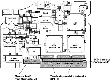
Tandberg Data Mounting Specifications
Service Port! Test Connector J3
Termination resistor networks RP1-3
Figure 4.4 The TDC 4100 Mainboard
4.2.2. Enable/Disable Bus Parity Checking
SCSI Interface Connector J1
The Drive Parity Checking is enabled/disabled by means of a strap between the PARI-pin and GND (Ground).
4.2.3. Extemal SCSI-bus Termination
Since the data cartridge is only specified up to 45°C, we recommend that the bus termination option inside the Drive is NOT used as this will cause unnecessary heat dissipation inside the Drive.
To avoid this, the TDC 4100 Drive must be placed between other SCSI-devices on the SCSI-bus. However, if this is not possible, we suggest that the bus is terminated with a special flat-ribbon bus terminator which can be mounted at the end of the cable.
IMPORTANT!
Remember to remove the three single-in-line resistor networks
inside the Drive when the Drive is NOT mounted at the end of the SCSI-bus or when external SCSI-bus termination is used! (See Figure 4.4 above).
4-4 TOC 4100 Reference Manual
/
"
\
mlllll)11
Q
1111
(jJ))
I
TESTI
SEL2 CLOSED OPENCLOSED OPEN CLOSED OPEN CLOSED OPEN CLOSED CLOSED CLOSED CLOSED CLOSED CLOSED CLOSED CLOSED
(
4.2.4. serlolln/Out Communication
The IN and OUT signal pins are used to connect the Drive to certain test tools. In particular the serial communication is used for adjusting the Drive with the TDT 4120 BIRD Test System.
4.2.5. Test Functions
The Drive has several test functions that can easily be started by setting up a specific code on the select straps (SELO - SEL2), and by grounding the TEST-pin during drive power-up. The coding is as follows:
I
SEL1 ISELOI
Meaning OPEN OPEN Burn-InOPEN CLOSED Selftest 2 CLOSED OPEN Reserved CLOSED CLOSED Reserved OPEN OPEN Reserved
OPEN CLOSED ERASE FWD/REV
CLOSED OPEN WRITE + ERASE FWD/REV CLOSED CLOSED WIND/REWIND
The different tests are described in detail in Chapter 10, Section 10.1.2. The Manually Activated Selftests.
Temporary Host
Tandberg Data Mounting Specifications
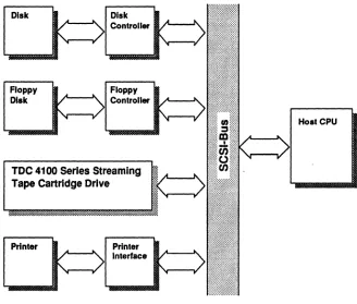
4.3. SCSI-Bus Interface Configuration
Figure 4.5 shows a typical SCSI-bus configuration making use of the Drive. In this system, each peripheral device has either a separate or an embedded interface-controller to make it compatible with the SCSI-bus specifications. The whole bus is connected to the Host via a special interface to allow other host operations while the SCSI-bus is busy. In a SCSI-bus system (see Figure 4.5), the Host will activate a particular peripheral device when necessary. However, when needed, one of the other peripheral devices may take over the bus, acting as a temporary host until that particular operation is completed.
NOTE:
The Drive has built-in termination resistor network. This network MUST be REMOVED if the Drive is not mounted in either end of the SCSI-bus cable or if external bus termination is used.
See Section 4.2.3. and Figure 4.4.
Disk
Floppy Disk
Disk Controller
Floppy Controller
TOe 4100 Series Streaming Tape cartridge Drive
Printer Printer Interface
b
I
Host CPU
Figure 4.5 Block diagram of a system with SCSI·bus interface
(
(
Tandberg Data Mounting Specifications
4.4.
Heat Dissipation
The Drive dissipates typically 15 W when running, and 3.5 W in stand-by. Part of this energy is dissipated in the cartridge itself while the tape is running. As a rule of the thumb, the base-plate temperature of a typical cartridge will increase about 7°C during a run of 27 minutes.
To avoid unnecessary temperature build-up when the Drive is in the idle mode, i.e. when the tape is not running, power to the write- and read-circuitry is turned off.
The maximum allowed internal temperature in the Drive in operating mode is limited by the media. The specifications for the 3M cartridge is 5 - 45°C, humidity at 20 - 80 %, and maximum Wet Bulb temperature is set to 26°C. (See also Section 3.3.1).
Care should be taken, when designing a system, to provide sufficient cooling possibilities to meet the cartridge specifications above. It is of course of importance not to terminate the SCSI-bus inside the Drive as this will dissipate unwanted heat inside the drive unit. We recommend that the SCSI Drive is not located in either of the ends of the SCSI-bus cable; in which case NO Drive termination circuitry is required. See Section 4.2.3.
It is also possible to use specially designed bus-terminators on the cable itself.
IMPORTANT!
Do NOT cover the ventilation holes in the chassis when mount-ing the Drive! The Drive must NEVER be mounted or placed top or bottom-flush against a flat surface as this will impede air
flow! Allow at least 10 mm (0.4") clearance to the table top if
testing the Drive!
It should be noted that in some applications it may be necessary to pro-vide forced ventilation.
It is important that the cartridge operating specifications are not vio-lated. Thus, when testing at system level the two following control points are recommended for temperature measurements:
<D
The air surrounding the head. (Measur