Volume 2006, Article ID 61927, Pages1–18 DOI 10.1155/ASP/2006/61927
A Human Body Analysis System
Vincent Girondel, Laurent Bonnaud, and Alice Caplier
Laboratoire des Images et des Signaux (LIS), INPG, 38031 Grenoble, France
Received 20 July 2005; Revised 10 January 2006; Accepted 21 January 2006
Recommended for Publication by Irene Y. H. Gu
This paper describes a system for human body analysis (segmentation, tracking, face/hands localisation, posture recognition) from a single view that is fast and completely automatic. The system first extracts low-level data and uses part of the data for high-level interpretation. It can detect and track several persons even if they merge or are completely occluded by another person from the camera’s point of view. For the high-level interpretation step, static posture recognition is performed using a belief theory-based classifier. The belief theory is considered here as a new approach for performing posture recognition and classification using imprecise and/or conflicting data. Four different static postures are considered: standing, sitting, squatting, and lying. The aim of this paper is to give a global view and an evaluation of the performances of the entire system and to describe in detail each of its processing steps, whereas our previous publications focused on a single part of the system. The efficiency and the limits of the system have been highlighted on a database of more than fifty video sequences where a dozen different individuals appear. This system allows real-time processing and aims at monitoring elderly people in video surveillance applications or at the mixing of real and virtual worlds in ambient intelligence systems.
Copyright © 2006 Hindawi Publishing Corporation. All rights reserved.
1. INTRODUCTION
Human motion analysis is an important area of research in computer vision devoted to detecting, tracking, and under-standing people’s physical behaviour. This strong interest is driven by a wide spectrum of applications in various areas such as smart video surveillance [1], interactive virtual real-ity systems [2,3], advanced and perceptual human-computer interfaces (HCI) [4], model-based coding [5], content-based video storage and retrieval [6], sports performances analy-sis and enhancement [7], clinical studies [8], smart rooms and ambient intelligence systems [9,10], and so forth. The “looking at people” research field has recently received a lot of attention [11–16]. Here, the considered applications are video surveillance and smart rooms with advanced HCIs.
Video surveillance covers applications where people are being tracked and monitored for particular actions. The de-mand for smart video surveillance systems comes from the existence of security-sensitive areas such as banks, depart-ment stores, parking lots, and so forth. Surveillance cameras video streams are often stored in video archives or recorded on tapes. Most of the time, these video streams are only used “after the fact” mainly as an identification tool. The fact that the camera is an active sensor and a real-time processing me-dia is therefore sometimes unused. The need is the real-time
video analysis of sensitive places in order to alert the police of a burglary in progress, or of the suspicious presence of a person wandering for a long time in a parking lot. As well as obvious security applications, smart video surveillance is also used to measure and control the traffic flow, compile consumer demographics in shopping malls, monitor elderly people in hospitals or at home, and so forth.
As this system is designed to track vehicles or people, hu-man subjects are not big enough in the frame, so the individ-ual body components cannot be reliably detected. Therefore the recognition of human activities is restricted to gait analy-sis. In [18], an automated visual surveillance system that can classify human activities and detect suspicious events in a scene is described. This real-time system detects people in a corridor, tracks them, and uses dynamic information to recognise their activities. Using a set of discrete and previ-ously trained hidden Markov models (HMMs), it manages to classify people entering or exiting a room, and even mock break-in attempts. As there are many other possible activ-ities in a corridor, for instance speaking with another per-son, picking up an object on the ground, or even lacing shoes squatting near a door, the system has a high false alarm rate. For advanced HCIs, the next generation will be multi-modal, integrating the analysis and recognition of human body postures and actions as well as gaze direction, speech, and facial expressions analysis. The final aim of [4] is to de-velop human-computer interfaces that react in a similar way to a communication between human beings. Smart rooms and ambient intelligence systems offer the possibility of mix-ing real and virtual worlds in mixed reality applications [3]. People entering a camera’s field of view are placed into a virtual environment. Then they can interact with the envi-ronment, with its virtual objects and with other people (us-ing another instance of the system), by their behaviour (ges-tures, pos(ges-tures, or actions) or by another media (for instance, speech).
Pfinder is a real-time system designed to track a single human in an indoor environment and understand its phys-ical behaviour [2]. It models the human body and its parts using small blobs with numerous characteristics (position, colour, shape, etc.). The background and the human body are modelled with Gaussian distributions and the human body pixels are classified as belonging to particular body parts us-ing the log-likelihood measure. Nevertheless, the presence of other people in the scene will affect the system as it is de-signed for a single person. Pfinder has been used to explore several different HCIs applications. For instance, in ALIVE and SURVIVE (resp., [9,10]), a 3D virtual game environ-ment can be controlled and navigated through by the user gestures and position.
In this paper, we present a system that can automati-cally detect and track several persons, their faces and hands, and recognise in real-time four static human body postures (standing, sitting, squatting, and lying). Whereas our previ-ous publications focused on a single part of the system, here the entire system is described in detail and both an evalu-ation of the performances and a discussion are given. Low-level data are extracted using dynamic video sequence anal-ysis. Then, depending on the desired application, part or all of these data can be used for human behaviour high-level recognition and interpretation. For instance, static posture recognition is performed by data fusion using the belief the-ory. The belief theory is considered here as a new approach for performing posture recognition.
1.1. Overview
Overview of the paper
Sections 2 to 5 present the low-level data extraction pro-cessing steps: 2D segmentation of persons (Section 2), ba-sic temporal tracking (Section 3), face and hands localisation (Section 4), and Kalman filtering-based tracking (Section 5). Section 6 illustrates an example of high-level human be-haviour interpretation, dealing with static posture recogni-tion. FinallySection 7concludes the paper, discusses the re-sults of the system, and gives some perspectives.
Overview of the system
As processing has to be close to real-time, the system has some constraints in order to design low-complexity algo-rithms. Moreover, with respect to the considered applica-tions, they are not so restrictive. The general constraints, nec-essary for all processing steps, are
(1) the environment is filmed byone static camera; (2) people are the only bothbigandmobile objects; (3) each person enters the scenealone.
The constraint 1 comes from the segmentation process-ing step, as it is based on a background removal algorithm. The constraints 2 and 3 follow from the aim of the system to analyse and interpret human behaviour. They are assumed to facilitate the tracking, the face and hands localisation, and the static posture recognition processing steps.
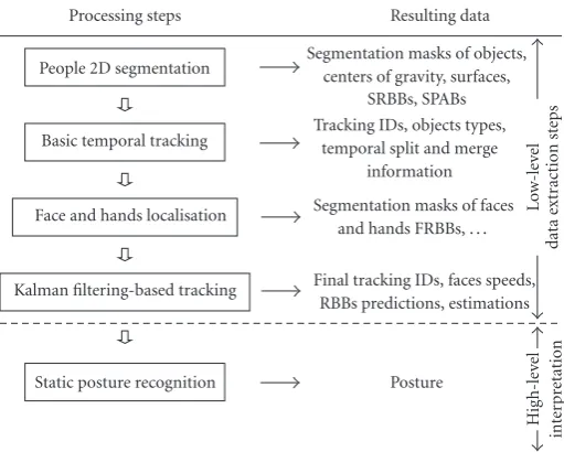
Figure 1gives an overview of the system. On the left side are presented the processing steps and on the right side the resulting data.Figure 2illustrates the processing steps.
Abbreviations
(i) FRBB: face rectangular bounding box.
(ii) FPRBB: face predicted rectangular bounding box. (iii) FERBB: face estimated rectangular bounding box. (iv) ID: identification number.
(v) PPRBB: person predicted rectangular bounding box. (vi) PERBB: person estimated rectangular bounding box. (vii) SPAB: segmentation principal axes box.
(viii) SRBB: segmentation rectangular bounding box.
2. PEOPLE 2D SEGMENTATION
Like most vision-based systems whose aim is the analysis of human motion, the first step is the extraction of persons present in the scene. Considering people moving in an un-known environment, this extraction is a difficult task [19]. It is also a significant issue since all the subsequent steps such as tracking, skin detection, and posture or action recognition are greatly dependent on it.
2.1. Our approach
Static posture recognition Kalman filtering-based tracking
Face and hands localisation Basic temporal tracking People 2D segmentation
Posture
Final tracking IDs, faces speeds, RBBs predictions, estimations Segmentation masks of faces
and hands FRBBs, . . . Tracking IDs, objects types,
temporal split and merge information
Segmentation masks of objects, centers of gravity, surfaces,
SRBBs, SPABs
Hi
gh
-l
ev
el
int
er
pr
etation
Lo
w-le
ve
l
data
ex
tr
action
st
eps
Processing steps Resulting data
Figure1: Overview of the system.
differences are used [20–22], but one of the major draw-backs is that no temporal changes occur on the overlapped region of moving objects especially if they are low textured. Moreover, if the objects stop, they are no more detected. As a result, segmented video objects may be incomplete. On the other hand, only a difference with a reference frame is used [23–25]. It gives the whole video object area even if the object is low textured or stops. But the main problem is the building and updating of the reference frame. In this paper, moving people segmentation is done using the Markov random field (MRF)-based motion detection algorithm developed in [26] and improved in [27]. The MRF modelling involves consecu-tive frame differences and a reference frame in a unified way. Moreover the reference frame can be built even if the scene is not empty.
The 2D segmentation processing step is summarized in Figure 3.
2.2. Labels and observations
Motion detection is a binary labelling problem which aims at attributing to each pixel or “site”s=(x,y) of frameIat time
tone of the two possible labels:
e(x,y,t)=e(s,t)=
⎧ ⎨ ⎩
obj ifsbelongs to a person, bg ifsbelongs to the background.
(1)
e = {e(s,t),s ∈I}represents one particular realization (at timet) of the label fieldE. Additionally, we define{e}as the set of possible realizations of fieldE.
With the constraint 1 of the system, motion information is closely related to temporal changes of the intensity func-tion I(s,t) and to the changes between the current frame
I(s,t) and a reference frameIREF(s,t) which represents the
static background without any moving persons. Therefore, two observations are defined:
(i) an observationOFD coming from consecutive frame differences:
oFD(s,t)=I(s,t)−I(s,t−1), (2)
(ii) an observationOREFcoming from a reference frame:
oREF(s,t)=I(s,t)−IREF(s,t)
oFD=
oFD(s,t), s∈I, oREF=
oREF(s,t), s∈I, (3)
representing one particular realization (at timet) of the observation fieldsOFDandOREF, respectively.
To find the most probable configuration of fieldEgiven fieldsOFDandOREF, we use the MAP criterion and look for
e∈ {e}, such that (Pr[·] denotes probability)
PrE=e/OFD=oFD,OREF=oREF max, (4)
which is equivalent to findinge ∈ {e}, such that (using the Bayes theorem)
Pr[E=e] PrOFD=oFD,OREF=oREF/E=e max. (5)
2.3. Energy function
The maximisation of this probability is equivalent to the minimisation of an energy functionUwhich is the weighted sum of several terms [28]:
Ue,oFD,oREF
=Um(e) +λFDUa
oFD,e
+λREFUa
1030
(a)
1030 Surface 18774
SPAB SRBB
Center of gravity
(b)
1030
P1
(c)
1030
P1 Face FRBB
Left hand Right hand
(d)
1030
P1 FPRBB
FERBB
PPRBB PERBB
(e)
1030 Sitting
P1
(f)
Figure2: Example of system processing steps. (a) Original frame, (b) people 2D segmentation, (c) basic temporal tracking, (d) face and hands localisation, (e) Kalman filtering-based tracking, and (f) static posture recognition.
The model energyUm(e) may be seen as a regularisation term that ensures spatio-temporal homogeneity of the masks of moving people and eliminates isolated points due to noise. Its expression resulting from the equivalence between MRF and Gibbs distribution is
Um(e)=
c∈C
Vc
es,er
. (7)
cdenotes any of the binary cliques defined on the spatio-temporal neighbourhood ofFigure 4.
A binary cliquec = (s,r) is any pair of distinct sites in the neighbourhood, including the current pixelsand anyone of the neighboursr.Cis the set of all cliques.Vc(es,er) is an elementary potential function associated to each cliquec =
(s,r). It takes the following values:
Vc
es,er
=
⎧ ⎨ ⎩−βr
ifes=er, +βr ifes=er,
(8)
where the positive parameterβrdepends on the nature of the clique:βr =20, βr =5, βr =50 for spatial, past temporal, and future temporal cliques, respectively. Such values have been experimentally determined once and for all.
Centers of gravity, surfaces, SRBBs, SPABs Segmentation masks
Morphological opening and closing ICM: minimisation ofU
Initalisation of fieldE OFD(s,t) OREF(s,t)
I(s,t−1) I(s,t) IREF(s,t)
Figure3: Scheme of the people 2D segmentation processing step.
t−1
t r r r
r s r
r r r
t+ 1
Central pixels
A neighbour A cliquec=(s,r)
Figure4: Spatio-temporal neighbourhood and binary cliques.
The link between labels and observations (generally notedO) is defined by the following equation:
o(s,t)=Ψe(s,t)+n(s), (9)
where
Ψe(s,t)=
⎧ ⎨ ⎩
0 ife(s,t)=bg,
α >0 ife(s,t)=obj, (10)
andn(s) is a Gaussian white noise with zero mean and vari-anceσ2.σ2is roughly estimated as the variance of each ob-servation field, which is computed online for each frame of the sequence so that it is not an arbitrary parameter.
function nor in the difference with the reference frame so each observation is quasi null; if the pixelsbelongs to a mov-ing person, a change occurs in both observations and each observation is supposed to be near a positive valueαFDand
αREF standing for the average value taken by each observa-tion.
Adequation energiesUa(oFD,e) andUa(oREF,e) are com-puted according to the following relations:
Ua
oFD,e= 1
2σ2 FD
s∈I
oFD(s,t)−Ψe(s,t) 2,
Ua
oREF,e
= 1
2σ2 REF
s∈I
oREF(s,t)−Ψ
e(s,t) 2.
(11)
Two weighting coefficientsλFD andλREFare introduced since the correct functioning of the algorithm results from a balance between all energy terms.λFD =1 is set once and for all, this value does not depend on the processed sequence.
λREFis fixed according to the following rules:
(i) λREF=0 ifIREF(s,t) does not exist: when no reference frame is available at pixels,oREF(s,t) does not influ-ence the relaxation process;
(ii)λREF=25 ifIREF(s,t) exists. This high value illustrates the confidence in the reference frame when it exists.
2.4. Relaxation
The deterministic relaxation algorithm ICM (iterated con-ditional modes [29]) is used to find the minimum value of the energy function given by (6). For each pixel in the im-age, its local energy is computed for each label (obj or bg). The label that yields a minimum value is assigned to this pixel. As the pixel processing order has an influence on the results, two scans of the image are performed in an ICM iter-ation, the first one from the top left to bottom right corner, the second one in the opposite direction. Since the greatest decrease of the energy functionUoccurs during the first it-erations, we decide to stop after four ICM iterations. More-over, one ICM iteration out of two is replaced by morpho-logical closing and opening, seeFigure 3. It results in an in-crease of the processing rate without losing quality because the ICM process works directly on the observations (tem-poral frame differences) computed from the frame sequence and does not work on binarised observation fields. The ICM algorithm is iterative and does not insure the convergence to-wards the absolute minimum of the energy function, there-fore an initialisation of the label fieldEis required: it results from alogical or between both binarised observation fields
OFDandOREF. This initialisation helps converging towards the absolute minimum and requires two binarisation thresh-olds which depend on the acquisition system and the envi-ronment type (indoor or outdoor).
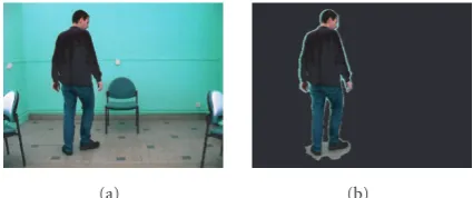
Once this segmentation process is performed, the la-bel field yields a segmentation mask for each video object present in the scene (single person or group of people). The segmentation masks are obtained through a connex com-ponent labelling of the segmented pixels whose label is obj. Figure 5shows an example of obtained segmentation in our
(a) (b)
Figure 5: Segmentation example. (a) Original frame, (b) seg-mented frame.
system. The results are good, the person is not split and the boundaries are precise, even if there are some shadows around the feet.
For each video object, single person, or group of people, once the segmentation mask is obtained, more low-level data are available and computed:
(i) surface: number of pixels of an object, (ii) centre of gravity of the object,
(iii) SRBB: segmentation rectangular bounding box, (iv) SPAB: segmentation principal axes box, whose
direc-tions are given by the principal axes of the object shape.
After this first step of low-level information extraction, the next step after segmentation is basic temporal tracking.
3. BASIC TEMPORAL TRACKING
In many vision-based systems, it is necessary to detect and track moving people passing in front of a camera in real time [1,2]. Tracking is a crucial step in human motion analysis, for it temporally links features chosen to analyse and inter-pret human behaviour. Tracking can be performed for a sin-gle human or for a group, seen as an object formed of several humans or as a whole.
3.1. Our approach
The tracking method presented in this section is designed to be fast and simple. It is used mainly to help the face local-isation step presented in the next section. Therefore it only needs to establish a temporal link between people detected at timetand people detected at timet−1. This tracking stage is based on thecomputation of the overlap of the segmenta-tion rectangular bounding boxes. The segmentation rectangu-lar bounding boxes are noted SRBBs. This method does not handle occlusions between people but allows the detection of temporal split and merge. In the case of a group of people, as there is only one video object composed of several persons, this group is tracked as a whole in the same way as if the ob-ject was composed of a single person.
As the acquisition rate of the camera is 30 fps, we can sup-pose that the persons in the scene have a small motion from one frame to the next, that is, there is always a non null over-lap between the SRBB of a person at timetand the SRBB of this person at timet−1. Therefore a basic temporal tracking is possible by considering only the overlaps between detected boxes at timetand those detected at timet−1. We do not use motion compensation of the SRBBs because it would require motion estimation which is time consuming.
In order to detect temporal split and merge and to ease the explanations, two types of objects are considered:
(i) SP: single person, (ii) GP: group of people.
This approach is similar to the one used in [30], where the types: regions, people, and group are used. When a new object is detected, with regard to constraint 3 of the system, this object is assumed to be an SP human being. It is given a new ID (identification number). GPs are detected when at least two SPs merge.
The basic temporal tracking between SRBBs detected on two consecutive frames (timet−1 andt) results from the combination of a forward tracking phase and a backward tracking phase. For the forward tracking phase, we look for the successor(s) of each object detected at time t −1 by computing the overlap surface between its SRBB and all the SRBBs detected at timet. In the case of multiple successors, they are sorted by decreasing overlap surface (the most prob-able successor is supposed to be the one with the greatest overlap surface). For the backward tracking phase, the proce-dure is similar: we look for the predecessor(s) of each object detected at timet. Considering a personPdetected at time
t: ifP’s most probable predecessor hasP as most probable successor, a temporal link is established between both SRBBs (same ID). If not, we look in the sorted lists of predecessors and successors until a correspondence is found, which is al-ways possible ifP’s box has at least one predecessor. If this is not the case,Pis a new SP (new ID).
As long as an object, that is, a single person or a group of people, is successfully tracked, without any temporal split or merge, its ID remains unchanged.
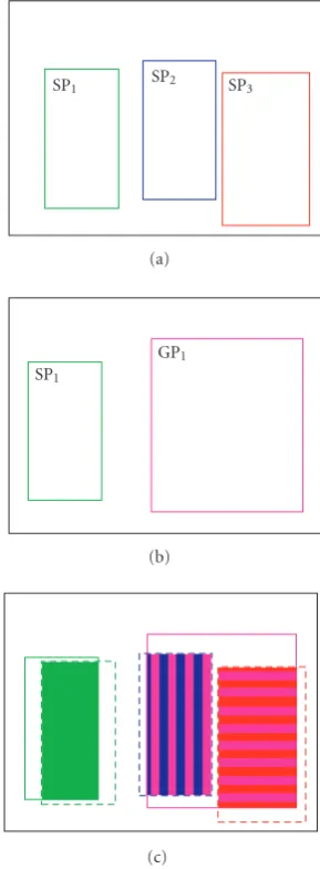
Figure 6illustrates the backward-forward tracking prin-ciple. InFigure 6(a), three objects are segmented, all SP, and inFigure 6(b), only two objects are segmented. On the over-lap frame (Figure 6(c)), the backward and forward trackings lead to a correct tracking for the object on the left side (there is only one successor and predecessor). It is tracked as an SP. For the object on the right side, the backward tracking yields two SP predecessors, and the forward tracking one successor. A merge is detected and it is a new group that will be tracked as a GP until it splits.
This basic temporal tracking is very fast and allows the following.
(i) Segmentation problems correction: if one SP has sev-eral successors, in case of a poor segmentation, we can merge them back into an SP and correct the segmentation.
SP1 SP2 SP3
(a)
SP1
GP1
(b)
(c)
Figure6: Overlap computation. (a) Frame at timet−1, (b) frame at timet, and (c) overlap frame.
(ii) GPsplit detection: if a GP splits in several SPs, nothing is done, but a split is detected.
(iii) SPmerge detection: if several SPs merge, the resulting object has several SP predecessors so it is recognised as a GP and a merge is detected.
Figure 7shows frames of a video sequence where two per-sons are crossing, when they are merging into a group and when this group is splitting. Segmentation results, SRBBs, and trajectories of gravity centres are drawn on the original frames. The trajectories are drawn as long as there is no tem-poral split or merge, that is, as long as the tracked object type does not change. In frame 124, tracking leads to SPP1on the left side and SPP2on the right side. In frame 125, a GPG1, composed ofP1 andP2, is detected. For the forward track-ing phase between times 124 and 125,P1andP2haveG1as the only successor. For the backward tracking phase,G1has
99
P1 P2
(a)
124
P1 P2
(b)
125
G1
(c)
139
G1
(d)
140
P3
P4
(e)
162
P3
P4
(f)
Figure7: Basic temporal tracking example. Frames 99, 124, 125, 139, 140, and 162 of two persons crossing.
this case, asP1andP2are SPs, a merge is detected. Therefore
G1is a new GP, which will be tracked until it splits again. It is the opposite on frames 139 and 140. The GPG1splits into two new SPs,P3andP4, that are successfully tracked until the end.
In the first tracking stage, a person may not be identi-fied as a single entity from beginning to end if there are more than one person present in the scene. This will be done by the second tracking stage. The results of this processing step are the identification numbers (IDs), the object types (SP or GP), and the temporal split and merge information. More-over, the trajectories for the successfully tracked objects are available.
In this paper, the presented results have been obtained after carrying out experiments on a great majority of se-quences with one or two persons, and on a few sese-quences with three. We consider that it is enough for the aimed ap-plications (HCIs, indoor video surveillance, and mixed re-ality applications). The constraint 2 of the system specifies that people are the only both big and mobile objects in the scene. For this reason, up to three different persons can be ef-ficiently tracked with this basic temporal tracking method. If there are more than three persons, it is difficult to determine, for instance, whether a group of four persons have split into two groups of two persons or into a group of three persons and a single person.
After this basic temporal tracking processing step, the next step is face and hands localisation.
4. FACE AND HANDS LOCALISATION
Numerous papers on human behaviour analysis focus on face tracking and facial features analysis [31–33]. Indeed, when looking at people and interacting with them, our gaze focuses on faces, as the face is our main expressive commu-nication medium, followed by the hands and our global pos-ture. Hand gesture analysis and recognition is also a large re-search field. The localisation of the face and of the hands, with right/left distinction, is also an interesting issue with respect to the considered applications. Several methods are available to detect faces [33–35]: using colour information [36,37], facial features [38,39], and also templates, optic flow, contour analysis, and a combination of these meth-ods. It has been shown in those studies that skin colour is a strong cue for face detection and tracking and that it clusters in some well-chosen colour spaces.
4.1. Our approach
With our constraints, for computing cost reasons, the same method has to be used to detect the face and the hands in or-der to achieve real-time processing. As features would be too complex to define for hands, a method based on colour is better suited to our application. When the background has a colour similar to the skin, this kind of method is perhaps less robust than a method based on body modelling. However, re-sults have shown that the proposed method works on a wide range of backgrounds, providing efficient skin detection. In this paper, we present a robust and adaptive skin detection method working in the YCbCr colour space and based on an adaptive thresholding in the CbCrplane. Several colour spaces have been tested and theYCbCrcolour space is one of those that yielded the best results [40,41]. A method of selecting the face and hands among skin patches is also de-scribed. For this processing step, only the general constraints (1, 2, and 3) are assumed. When the static posture recogni-tion processing step was developed, we had to define a ref-erence posture (standing, both arms stretched horizontally), seeSection 6.1. Afterwards, we decided to use this reference posture, if it occurs and if necessary, to reinitialise the face and hands locations.
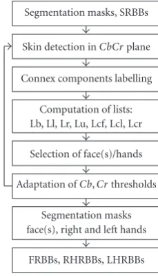
Figure 8summarises the face/hands localisation step.
4.2. Skin detection
This section describes the detection of skin pixels, based on colour information. For each SRBB (segmentation rectangu-lar bounding box) provided by the segmentation step, we look for skin pixels. Only the segmented pixels inside the SRBBs are processed. Thanks to this, few background pixels (even if the background is skin colour-like) are processed.
FRBBs, RHRBBs, LHRBBs Segmentation masks face(s), right and left hands Adaptation ofCb,Crthresholds
Selection of face(s)/hands Computation of lists: Lb, Ll, Lr, Lu, Lcf, Lcl, Lcr Connex components labelling
Skin detection inCbCrplane Segmentation masks, SRBBs
Figure8: Scheme of the face and hands localisation processing step.
(a) (b)
Figure9: Skin database. (a) Von Luschan frame, (b) 6 skin samples.
colours of hands or arms. The skin frames are acquired with the camera and frame grabber we use in order to take into account the white balance and the noise of the acquisition system.
Figure 10is a 2D plot of all pixels from the skin database on theCbCrplane with an average value ofY. It exhibits two lobes: the left one corresponds to the Von Luschan skin sam-ples frame and the right one to the twenty skin samsam-ples ac-quired with our camera and frame grabber.
Figure 11shows an example of skin detection where op-timal manually tuned thresholds were used. Results are good: face and hands (arms here) are correctly detected with accu-rate boundaries.
TheCbCrplane is partitioned into two complementary areas: skin area and non-skin area. A rectangular model for the skin area shape yields a good detection quality with a low computing cost. It limits the required computations to a dou-ble thresholding (low and high) for eachCbandCr compo-nent. As video sequences are acquired in theYCbCr4 : 2 : 0 format,CbandCrcomponents are subsampled by a factor of 2. The skin/non-skin decision for a 4×4 pixels block of the segmented frame is taken after the computation of the aver-age values of a 2×2 pixels block in eachCborCrsubframe.
Cb
Cr
Figure10: 2D plot of all skin samples pixels.
290
(a)
290 P1
(b)
Figure11: Example of skin detection. (a) Original frame, (b) skin detection.
Those mean values are then compared with the four thresh-olds. Computation is therefore even faster.
A rectangle containing most of our skin samples is de-fined byCb∈[86; 140] andCr ∈[139; 175] (big rectangle ofFigure 10). This rectangle is centred on the mean values of the lobe corresponding to our skin samples frames to ad-just the detection to our acquisition system. The right lobe is not completely included in the rectangle in order to avoid too much false detection. In [42] considered thresholds are slightly differentCb∈[77; 127] andCr ∈[133; 173], which justifies the tuning of parameters to the first source of vari-ability, that is, the acquisition system and the lighting condi-tions. The second source of variability is the interindividual skin colour. Each small rectangle ofFigure 10only contains skin samples from a particular person in a given video se-quence. Therefore it is also useful to automatically adapt the thresholds to each person during the detection process in or-der to improve the skin segmentation.
Several papers detail the use of colour models, for in-stance Gaussian pdf in theHSIorrgbcolour space [36], and perform an adaptation of model parameters. An evaluation of Gaussianity ofCbandCrdistributions was performed on the pixels of the skin database. As a result, approximately half of the distributions cannot be reliably represented by a Gaussian distribution [41]. Therefore thresholds are directly adapted without considering any model.
applied separately to both dimensions Cband Cr). These transformations are performed with respect to the mean val-ues of the face skin pixels distribution of the considered per-son. Only the skin pixels of the face are used, as the face moves more slowly and is easier to detect than hands. This prevents the adaptation from being biased by detected noise or false hands detection. Three transformations are consid-ered for the threshold adaptation.
(i) Translation: the rectangle is gradually translated to-wards the mean values of skin pixels belonging to the selected face skin patch. The translation is of only one colour unit per frame in order to avoid transitions being too sharp. The translated rectangle is also con-strained to remain inside the initial rectangle.
(ii)Reduction:the rectangle is gradually reduced (also of one colour unit per frame). Either the low threshold is incremented or the high threshold is decremented so that the reduced rectangle is closer to the observed mean values of skin pixels belonging to the face skin patch. Reduction is not performed if the adapted rect-angle reaches a minimum size (15×15 colour units). (iii)Reinitialisation:the adapted rectangle is reinitialised to
the initial values if the adapted thresholds lead to no skin patch detection.
Those transformations are applied once to each detection interval for each frame of the sequence. As a result, skin de-tection should improve over time. In most cases, the adapta-tion needs∼30 frames (∼1sof acquisition time) to reach a stable state.
4.3. Face and hands selection
This section proposes a method in order to select relevant skin patches (face and hands). Pixels detected as skin after the skin detection step are first labelled into connex compo-nents that can be either real skin patches or noise patches. All detected connex components inside a given SRBB are asso-ciated to it. Then, among these components, for each SRBB, skin patches (if present) have to be extracted from noise and selected as face or hands. To reach this goal, several criteria are used. Detected connex components inside a given SRBB are sorted in decreasing order in lists according to each cri-terion. The left or right side of the lists are from the user’s point of view.
Size and position criteria are the following.
(i) List of biggest components (Lb): face is generally the biggest skin patch followed by hands, and other smaller patches are generally detection noise.
(ii) List of leftmost components (Ll): useful for left hand. (iii) List of rightmost components (Lr): useful for right
hand.
(iv) List of uppermost components (Lu): useful for face.
Temporal tracking criteria are the following.
(i) List of closest components to last face position (Lcf). (ii) List of closest components to last left hand position
(Lcl).
(iii) List of closest components to last right hand position (Lcr).
Selection is guided by heuristics related to human mor-phology. For example, the heuristics used for the face selec-tion are that the face is supposed to be the biggest, the upper-most skin patch, and the closest to the previous face position. The face is the first skin patch to be searched for because it has a slower and steadier motion than both hands and there-fore can be found more reliably than hands. Then the skin patch selected as the face is not considered any longer. After the face selection, if one hand was not found in the previous frame, we look for the other first. In other cases, hands are searched without any a priori order.
Selection of the face involves (Lb, Lu, Lcf), selection of the left hand involves (Lb, Ll, Lcl), and selection of the right hand involves (Lb, Lr, Lcr). The lists are weighted depending on the skin patch to find and if a previous skin patch position exists. The list of biggest components is given a unit weight. All other lists are weighted relatively to this unit weight. If a previous skin patch position exists, the respective list of clos-est components is given a triple weight. As the hand does not change side from one frame to another, if the skin patch pre-vious position is on the same side as the respective side list (Lr for the right hand), this list is given a double weight. The top elements of each list are considered as likely candidates. When the same element is not at the top of all lists, the next elements in the list(s) are considered. The skin patch with the maximum weighted lists rank sumis finally selected.
For the face, in many cases there is a connex component that is at the top of those three lists. In the other cases, Lcf (tracking information) is given the biggest weight because face motion is slow and steady. The maximum rank consid-ered in other lists is limited to three in order to avoid unlikely situations and poor selection.
After selection, the face and right and left hands rectan-gular bounding boxes are also computed (noted, resp., FRBB, RHRBB, and LHRBB). For the face skin patch, considering its slow motion, we add the constraint of a non null rect-angular bounding box overlap with its successor. This helps to handle situations where a hand passes in front of the face. Moreover, if the person is in the reference posture (see Section 6), this posture is used to correctly reinitialise the lo-cations of the face and of the hands in the case of a poor selection or a tracking failure.
Figure 12illustrates some results of face/hands localisa-tion. Skin detection is performed inside the SRBB. Face and hands are correctly selected and tracked as shown by the small rectangular bounding boxes. Moreover, even if the per-son crosses his arms (frames 365 and 410), the selection is still correct.
110
P1
(a)
365
P1
(b)
390
P1
(c)
410
P1
(d)
Figure12: Face and hands localisation. Frames number 110, 365, 390, and 410.
are not used in the rest of this paper but have been used in other applications, like theart.liveproject [3].
5. KALMAN FILTERING-BASED TRACKING
The basic temporal tracking presented inSection 3does not handle temporal split and merge of people or groups of peo-ple. When two tracked persons merge into a group, the basic temporal tracking detects the merge but tracks the resulting group as a whole until it splits. Then people in the group are tracked again but without any temporal link with the previ-ous tracking of individuals. InFigure 7two personsP1andP2 merge into a groupG1. When this group splits again into two persons, they are tracked asP3andP4, not asP1andP2. Tem-poral merge and occlusion make the task of tracking and dis-tinguishing people within a group more difficult [30,43,44]. This section proposes an overall tracking method which uses the combination of partial Kalman filtering and face pursuit to track multiple persons in real-time even in case of com-plete occlusions [45].
5.1. Our approach
We present a method that allows the tracking of multiple persons in real-time even when occluded or wearing simi-lar clothes. Apart from the general constraints of the system (1, 2, and 3), no other particular hypothesis is assumed here. We do not segment the persons during occlusion but we ob-tain bounding boxes estimating their positions. This method is based on partial Kalman filtering and face pursuit. The Kalman filter is a well-known optimal and recursive signal processing algorithm for parameters estimation [46]. With respect to a given model of parameters evolution, it com-putes the predictions and adds the information coming from the measurements in an optimal way to produce a posteriori estimation of the parameters. We use a Kalman filter for each new detected person. The global motion of a person is
Final tracking IDs, faces speeds PPRBBs, FERBBs, FPRBBs, FERBBs
Kalman filtering Attribution of measurements
Selection ofKFmode:
SPCompKF,SPParKF,GPParKF,GPPreKF
Estimation of faces motion Segmentation masks,
SRBBs, FRBBs
Figure13: Scheme of the Kalman filtering-based tracking process-ing step.
supposed to be the same as the motion of this person’s face. Associated with a constant speed evolution model, this leads to a state vectorxof ten components for each Kalman filter: the rectangular bounding boxes of the person and of his/her face (four coordinates each) and two components for the 2D apparent face speed:
xT=x
pl,xpr,ypt,ypb,xf l,xf r,yf t,yf b,vx,vy
. (12)
InxTexpression,pand f, respectively, stand for the per-son and face rectangular bounding box,l,r,t, andb, respec-tively, stand for left, right, top, and bottom coordinate of a box.vx andvy are the two components for the 2D appar-ent face speed. The evolution model leads to the following Kalman filter evolution matrix:
At =A= ⎡ ⎢ ⎢ ⎢ ⎢ ⎢ ⎢ ⎢ ⎢ ⎢ ⎢ ⎢ ⎢ ⎢ ⎢ ⎢ ⎢ ⎣
1 0 0 0 0 0 0 0 1 0 0 1 0 0 0 0 0 0 1 0 0 0 1 0 0 0 0 0 0 1 0 0 0 1 0 0 0 0 0 1 0 0 0 0 1 0 0 0 1 0 0 0 0 0 0 1 0 0 1 0 0 0 0 0 0 0 1 0 0 1 0 0 0 0 0 0 0 1 0 1 0 0 0 0 0 0 0 0 1 0 0 0 0 0 0 0 0 0 0 1 ⎤ ⎥ ⎥ ⎥ ⎥ ⎥ ⎥ ⎥ ⎥ ⎥ ⎥ ⎥ ⎥ ⎥ ⎥ ⎥ ⎥ ⎦
. (13)
Figure 13summarises the Kalman filtering-based track-ing processtrack-ing step.
5.2. Face motion estimation
For each face that is detected, selected, and located at time
5.3. Notations
The segmentation step may provide SRBBs (segmentation rectangular bounding boxes) that can contain one or several persons in it (in the case of a merge), whereas the Kalman state vector (and therefore the Kalman person rectangular bounding box) is defined for a single person. Therefore three different person rectangular bounding boxes exist and are as-sociated to each person:
(i) one segmentation rectangular bounding box (SRBB) provided by the segmentation step,
(ii) one person predicted rectangular bounding Box (PPRBB) predicted by Kalman filtering,
(ii) one person a posteriori estimated rectangular bound-ing box (PERBB) estimated by Kalman filterbound-ing.
In a similar way, three different face rectangular bound-ing boxes exist and are associated to each person:
(i) one face rectangular bounding box (FRBB) provided by the face localisation step,
(ii) one face predicted rectangular bounding box (FPRBB) predicted by Kalman filtering,
(iii) one face a posteriori estimated rectangular bounding box (FERBB) estimated by Kalman filtering.
5.4. Kalman filtering modes
Measurements that are injected into the Kalman filter come from the SRBBs, the FRBBs, and the face motion estimations. All the measurements are not necessarily available. For in-stance, if two persons have just merged into a group, some measurements are not available, on the group SRBB, for each person’s PPRBB estimation (e.g., one side measurement will not be available).
Depending on the objects types and available measure-ments, there are four Kalman filtering modes:
(1) SPCompKF: single person complete Kalman filtering, (2) SPParKF: single person partial Kalman filtering, (3) GPParKF: group of people partial Kalman filtering, (4) GPPreKF: group of people predictive Kalman filtering.
First, we must determine if we are in a single person mode or a group of people mode, that is, if the person SRBB contains only one person or not. This is given by the basic temporal tracking step, as we can detect a merge between two SP objects, we know if there is one person or more in each SRBB.
If the SRBB contains only one person, all measurements used for the PPRBB estimation are available. Then either the face was correctly located at timest−1 and at timetor not. If so, we are inSPCompKFmode as all state vector measure-ments are available. Otherwise we are inSPParKFmode as some face-related measurements are not available.
If the SRBB contains several persons, some measure-ments are not available for the PPRBBs estimation. Depend-ing on whether there is only one face overlapped by the PERBB or not, we are, respectively, inGPParKFmode or in GPPreKFmode.
5.4.1. Single person complete Kalman filtering mode
This mode is selected when there is no temporal merge and all face-related measurements are available.
(i) The SRBB contains only one person (all measurements for the PPRBB estimation are available).
(ii) The person’s face is located at timet(all measurements for the FPRBB estimation are available).
(iii) The person’s face has been located at timet−1 (face speed estimation measurements are available).
In this mode, the Kalman filtering is carried out for all state vector components.
5.4.2. Single person partial Kalman filtering mode
This mode is selected when there are no temporal merge but some or all face-related measurements are not available. If so, face localisation step has failed at timet−1 and/or at timet, leading to unavailable measurements.
When there are unavailable measurements, two choices are possible. The first is to perform a Kalman filtering only on the available measurements and the other is to replace the unavailable measurements. Performing a Kalman filter-ing only on available measurements is a difficult issue for code implementation, as all matrix sizes have to be predicted in order to take into account all possible cases. Replacing un-available measurements by predictions is a simple and in-tuitive way of performing a Kalman filtering when observa-tions (available measurements) are missing. Hence, in order to perform a Kalman filtering for all state vector components in one computation, when there are unavailable measure-ments, they are replaced by predictions. Doing so does not seem to greatly influence the results because the variances of estimation errors are only of a few pixels, with respect to available measurements.
In this mode, the filtering is carried out for all compo-nents, including those that have been replaced by predicted values.
5.4.3. Group of people partial Kalman filtering mode
This mode is selected when there are temporal merge(s) (i.e., some measurements are not available for the PPRBB estima-tion) and when the PERBB overlaps a unique face.
As the SRBB contains a group of people, available mea-surements can be used for different PPRBBs. The attribution of available measurements to one person in a group is per-formed in two steps by comparing the group SRBB and each person PPRBB centres and sides coordinates. The principle of measurements attribution is illustrated on frame 203 of Figure 14.
200
P1
P2
(a)
203
P1
P2
(b)
212
P1
P2
(c)
219
P1
P2
(d)
221
P1
P2
(e)
228
P1
P2
(f)
Figure14: Example of multiple persons tracking with complete oc-clusion.
merged (hands touching), we have only four measurements available (instead of eight) that can be used as observations for the two PPRBBs. With the first step, personP1will have the left and bottom sides coordinates as measurements, per-son P2 will have the right and bottom sides coordinates. Thanks to this step, we are sure that at least two measure-ments are used for each PPRBB estimation.
In the second step, we compare each PPRBB side coor-dinate to the corresponding SRBB side. If the distance be-tween both is smaller than a threshold, depending on each PPRBB surface, and if it has not already been taken into ac-count, the corresponding SRBB side coordinate is added to the measurements used for the PPRBB estimation. With this step, in our example, the personP1receives the top side co-ordinate of the SRBB as an added measurement. This step generally allows adding one or two measurements in order to perform a better estimation.
In the example ofFigure 14, the left, top, and bottom side measurements of the SRBB will be used as measurements for the PPRBB on the left side (personP1). The right and bot-tom side measurements will be used as measurements for the PPRBB on the right side (personP2). As for the bottom side measurement in the example, some measurements can be used for different persons. For each person, in thisGPParKF mode, we generally have two or three available measurements (up and/or down side(s) and one side measurements).
If some face-related measurements are unavailable, Kal-man predicted values replace the missing measurements. The filtering is performed as long as the PERBB contains a unique face. If the PERBB overlaps more than one face, even par-tially, the Kalman filter works in GPPreKF mode since the face localisation step could provide wrong positions.
5.4.4. Group of people predictive mode
This mode is selected when temporal merge(s) occur (i.e., some measurements are not available for the PPRBB estima-tion) and when the PERBB overlaps more than one face.
No measurements are taken into account. All the state vector components are predicted according to the last face speed estimation, that is, only the Kalman filter predictions equations are used. The Kalman filter works in GPPreKF mode until a unique face is again overlapped by one of the PERBBs, leading back to theGPParKFmode.
5.5. Results
Figure 14 illustrates a successful multiple persons tracking performed on a video sequence in which two persons are crossing and turning one around the other. In this sequence, the moving directions and speeds are not constant and, at some moments, a person is completely occluded, see for in-stance frame 212. Segmented and tracked persons are visible on the original frames of the sequence. SP or GP SRBBs are drawn in white lines, PERBBs and FERBBs in dashed lines. Frames 200 and 228 show aSPCompKFmode tracking with all measurements available for the Kalman filters before the merge (frame 203) and after the split (frame 228). Frames 212 and 219 illustrate the tracking in aGPPreKFmode when one face is occluded. Frames 203 and 221 (just before the split) illustrate the tracking inGPParKFmode.
In single person Kalman filtering modes, SPCompKF mode, andSPParKF mode, the person final tracking ID is the same as the basic temporal tracking ID, because there are no temporal split or merge. In group of people modes, GPParKF andGPPreKF, the final tracking IDs are not up-dated with the basic temporal tracking IDs, as temporal split and merge yield new IDs. Therefore it is possible to track multiple persons even under complete occlusions. The ex-tracted information for this processing step consists of the fi-nal tracking IDs, the face speed estimation, the PPRBBs, the PERBBs, the FPRBBs, and the FERBBs, that is, the predicted and a posteriori estimated rectangular boxes of the person and of his/her face.
This section presented the last processing step for low-level data extraction. Part of the data will now be used for higher-level processing.
6. HIGH-LEVEL HUMAN BEHAVIOUR
INTERPRETATION: STATIC POSTURE RECOGNITION
action/pose recognition and description. The three main ap-proaches used for human behaviour analysis used are dy-namic time warping (DTW) [47], hidden Markov models (HMMs) [48], and neural networks (NNs) [49]. Most of the research work done on the human body as a whole is mainly gait analysis and recognition, or recognition of simple inter-actions between people, or between people and objects. In this section, we present a method to recognise a set of four static human body postures (standing, sitting, squatting, and lying) thanks to data fusion using the belief theory [50,51].
The belief theory has been used for facial expression clas-sification (see [52,53]) but not for posture recognition in hu-man motion analysis. The TBM (transferable belief model) was introduced by Smets in [54,55]. It follows the works of Dempster [56] and Shafer [57]. The main advantage of the belief theory is the possibility to model data imprecision and conflict (a conflict occurs when measurements used for recognition yield contradictory results). It is also not com-putationally expensive, compared to HMMs and, as doubt (the possibility of recognising a union of postures instead of a unique one) is taken into account, leads to a low false alarm rate.
6.1. Our approach
Static recognition is based on information obtained by dy-namic sequence analysis. For this processing step, we assume the general constraints of the system (1, 2, and 3) and also the following two more hypotheses.
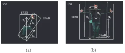
(i) Each person has to be at least once in areference pos-ture, standing with both arms stretched horizontally, also known as the “Da Vinci Vitruvian Man posture,” seeFigure 15(b).
(ii) Each person is to be filmedentirely(not occluded).
Three distances are computed, seeFigure 15:D1the ver-tical distance from the FRBB centre to the SRBB bottom,D2 the distance from the FRBB centre to the SPAB centre (grav-ity centre), and D3 the SPAB semi-great axe length. Each distance Di is normalised with respect to the correspond-ing distance Diref obtained when the person is observed in the reference posture in order to take into account the in-terindividual variations of height and the distance of the per-son with respect to the camera. The measurements are noted
ri=Di/Diref(i=1,. . ., 3).
6.2. Belief theory
The belief theory approach needs the definition of a worldΩ composed ofNdisjunctive hypothesesHi. Here the hypothe-ses are the following four static postures: standing (H1), sit-ting (H2), squatting (H3), and lying (H4). If the hypotheses are exhaustive,Ωis a closed world, that is, the truth is nec-essarily inΩ. In this paper, we consider an open world, as all possible human body postures cannot be classified in the considered postures. We add a hypothesis for the unknown posture class (H0), but this hypothesis is not included inΩ.
H0is a reject class: if we cannot recognise a posture between
550
SRBB
SPAB
D1
D2
D3
(a)
160
SRBB
SPAB
D1
D2
D3
(b)
Figure15: Examples of distancesDi. (a) Sitting posture, (b)
refer-ence posture.
our considered postures, we will recognise an unknown pos-ture. Therefore we haveΩ= {H1,H2,H3,H4}andH0. In this theory, we consider the 2NsubsetsAofΩ. In order to express the confidence degree in each subsetAwithout favouring one of its composing elements, an elementary belief massm(A) is associated to it.
Themfunction, or belief mass distribution, is defined by
m: 2Ω−→[0; 1],
A−→m(A) with
A∈2Ω
m(A)=1. (14)
6.2.1. Modelling
A model has to be defined for each measurement ri in or-der to associate an elementary belief mass to each subsetA, depending on the value ofri. In a similar way to what was proposed in [52], two different model types are used (see Figure 16). The first model type is used forr1 and the sec-ond forr2andr3.
The first model type is based on the idea that the lower the face of a person is located, the closer the person is to the lying posture. Conversely, the higher the face is located, the closer the person is to the standing posture. Depending on the value ofr1, either a single posture is recognised or the combination of a single posture and a union of two postures. In this last case the respective zones illustrate the impreci-sion and the uncertainty of the models (see, e.g.,Table 1and Figure 16(a)).
The second model type is based on the idea that squat-ting is a compact human shape, whereas sitsquat-ting is a more elongated shape. Standing and lying are even more elongated shapes. The thresholdsg−jare different forr2andr3. De-pending on the value of each measurementr2orr3, the sys-tem can set non null belief masses to the single postureH3, to the union of all postures (Ωcorresponds toH1∪H2∪H3∪H4 here), to the subset standing, sitting, or lying (H1∪H2∪H4), or to two of the previous subsets.
6.2.2. Data fusion
The aim is to obtain a belief mass distributionmr123that takes
Table1
r1value Hirecognised non null belief masses
f < r1 H1 mr1(H1)=1
e+f
2 < r1< f H1,H1∪H2 mr1
H1+mr1
H1∪H2=1
e < r1<
e+f
2 H1∪H2,H2 mr1
H1∪H2
+mr1
H2
=1
etc. etc. etc.
0 a b c d e f 1
r1
0 1
mr
1
H4 H3 H2 H1
H3∪H4 H2∪H3 H1∪H2
(a)
0 g h i j 1
r2,r3
0 1
mr
2
,
mr
3
H3 H1∪H2∪H4
Ω
(b)
Figure16: Belief models. (a) First model used formr1, (b) second
model used formr2andmr3.Hidefines recognised posture(s).
The orthogonal summri jof two distributionsmriandmrj
is defined, for eachAsubset of 2Ω, as follows:
mri j=mri⊕mrj,
mri j(A)=
B∈2Ω,C∈2Ω,B∩C=A
mri(B)·mrj(C).
(15)
The orthogonal sum is associative and commutative, so the order of the belief mass distributions fusion does not matter.
In case whenmr123(∅)=0,∅being the empty set, there
is aconflict, which means that the chosen models give con-tradictory results. This usually happens when some of theri are in the transition zones of the models. With these models, the subset with the maximum number of elements that can be obtained at the end of the data fusion process is a union of two postures. Therefore, subsets with three elements orΩ it-self cannot be obtained after fusion. Hence, we are sure that, in the worst case, there will be a possible confusion between two postures and not more. This is compliant with respect to the considered postures: it is difficult to imagine, for ex-ample, that a person can be simultaneously either standing, sitting, or lying.
6.2.3. Decision
The decision is the final step of the process. Once all the be-lief mass distributions have been combined into a single one, heremr123, there is a choice to make between the different
hypothesesHiand their possible combinations. A criterion defined on the final belief mass distribution is generally opti-mised to choose the classification resultA. For example, if the criterion is the belief mass,A=arg maxA∈2Ωmr123(A). Note
thatAmay not be a singleton but a union of several hypothe-ses or even the empty set. In this paper, the hypothesisH0is chosen if the classification result is the empty set∅, that is,
mr123(∅) is maximum. There are other criteria used to make
a decision: the belief, the plausibility, and so forth [54].
6.3. Posture recognition results
In order to evaluate the static posture recognition perfor-mances, two sets of video sequences are used, a training set and a test set. The training set consists of 12 different video sequences representing∼ 5000 frames. 6 different persons are filmed twice in the same 10 successive postures. People are of various heights, between 1.55 m and 1.95 m, in order to take into account the variability of heights and improve the robustness. The constraints are to be in “natural” postures in front of the camera. The statistics (meansμand standard de-viationsσ) of the three measurementsriare computed over the training set to find the thresholds (seeFigure 16) that yield a minimum of conflict. These most suitable thresholds are defined by the comparison of theμ±2σ computed for the respective postures or set of postures. This expertise step was performed by a human operator. In fact, one of the hard-est steps in the belief theory is to find models (or thresholds) that lead to a minimum of conflicts. The test set consists of 12 other video sequences representing∼11 000 frames. 6 other persons, also of various heights, are filmed twice in different successive postures. In order to test the limits of the system, people are allowed to move the arms, sit sideways, and even be in postures that do not often occur in everyday life, for instance squatting with arms raised above the head. Results are computed on frames of the video sequences where the global body posture is static, that is, the person’s torso and legs are approximately still. We present the classification re-sults obtained when using themaximum belief massas crite-rion. Comparison between criteria and subsequent classifiers is available in [51]. Training step and test step recognition rates are available in Tables2and3. Columns show the real posture and lines the postures recognised by the system.
Training step
Table2: Training step confusion matrix.
System\H H1 H2 H3 H4
H0 0% 0.1% 0% 0%
H1 100% 0% 0% 0%
H1∪H2 0% 0% 0% 0%
H2 0% 95.9% 1.0% 0%
H2∪H3 0% 2.1% 4.0% 0%
H3 0% 1.9% 95.0% 0%
H3∪H4 0% 0% 0% 0%
H4 0% 0% 0% 100%
Table3: Test step confusion matrix.
System\H H1 H2 H3 H4
H0 0% 10.3% 5.0% 0%
H1 99.5% 0.4% 0% 0%
H1∪H2 0.5% 0% 0% 0%
H2 0% 56.3% 20.3% 0%
H2∪H3 0% 27.1% 18.0% 0%
H3 0% 5.9% 56.7% 0%
H3∪H4 0% 0% 0% 0%
H4 0% 0% 0% 100%
Test step
There are more recognition errors but the results show a good global recognition rate. The average recognition rate is
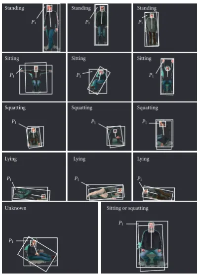
78.1%.There are never any problems recognising the stand-ing or the lystand-ing postures. For the sittstand-ing and the squattstand-ing postures, there are more errors, especially when people have their arms raised over their heads or sit sideways. The reasons are that these postures are quite alike and that not everybody sits and/or squats in the same way, hands on knees or touch-ing ground, back bent or straight, and so forth. These facts yields more conflicts, near 15%. There are also more postures that lead to the doubtH2∪H3. Nevertheless, the recognition rates are very close betweenH2versusH2andH3versusH3.
Figure 17illustrates some results of various static pos-tures recognition. The SRBB, the SPAB, the FRBB, and the
D2distance are drawn in white on the segmented frame.
7. CONCLUSION, DISCUSSION, AND PERSPECTIVES
7.1. Conclusion
We have presented in this paper a real-time system for multi-ple persons body analysis and behaviour interpretation. The processing rate of the whole system, obtained on a PC run-ning at 3.2 GHz is∼26 fps for 640×480 resolution (∼65 fps for 320×240). Compared with other similar systems likeW4 [1] and Pfinder [2], that surely meet the requirements to per-form a similar task, our system proposes relatively different approaches for dealing with the various processing steps and their inherent problems. It is generic enough to be used for
Unknown
P1
Sitting or squatting
P1
Lying
P1
Lying
P1
Lying
P1
Squatting
P1
Squatting
P1
Squatting
P1
Sitting
P1
Sitting
P1
Sitting
P1
Standing
P1
Standing
P1
Standing
P1
Figure17: Examples of static posture recognition.
several types of applications in either indoor or outdoor envi-ronment. For outdoor environments, some of the algorithms would need to be improved, with regard to the problems that can arise when acquisition conditions greatly vary. As long as the people are not too numerous and remain the main ob-jects, the results should be fairly reliable.
This system can be used for mixed reality applications with perceptual human-computer interfaces. In front of a single static camera, in an indoor environment, a single per-son or several perper-sons can interact with a virtual environ-ment and control it by their moveenviron-ments. The proposed sys-tem for mixing real and virtual worlds by image processing without invasive systems as markers and so forth yields re-sults with a suitable precision. It is fast enough for a respon-sive system that includes human-computer interaction and is relatively user-friendly. The other possible application is the monitoring of elderly people at home or in hospital rooms. One could detect for instance that someone has fallen down or has been sitting for too long. Considering elderly people, their postures should be similar to the training set ones of the static posture recognition step. In these conditions, the sys-tem should be reliable enough to succeed in this monitoring as the training recognition rates are very good. Nevertheless, tests must still be performed and implemented source code improved.
7.2. Discussion and perspectives