TECHNICAL BULLETIN
SLEUTH ASSEMBLY SYSTEM
Programmers Re-Ference
Firsf: Edif:ion
TABLE OF CONTENTS
I. INTRODUCTION . . . .
.
.
. .
.
.
. .
A. General Description •
B. Program Types . . . • .
C. Program Structure.
.
.
. .
.
II. ASSEMBLY LANGUAGE FORMAT AND SYMBOLOGY
.
.
.
.
.
A. Coding Form . • • . • . .
B. Number and Symbol Representation
III. COMPONENTS OF A LINE OF CODING. A. General Description .
B. Actual Values . . . .
C. Special Characters . • • .
D. Function Codes E. Tags and Labels . F. Designators ••
IV. MACHINE AND GENERATIVE INSTRUCTIONS
A. Machine Instructions B. Generative Instructions .
V. DECLARATIVE INSTRUCTIONS
A. Definition • . . • . B. Program Specification . C. Equality . • . . . • . D. Segmenting Instructions . E. Table Definition
F. List Spacing Instructions.
G. Selective Jump Switch Definition
VI. MACRO-INSTRUCTIONS . . .
A. Purpose • . . . .
.
.
.
.
.
.
.
.
. .
. . .
. .
. .
.
B. Defining a Macro-instruction
.
.
.
. . .
C. Generating a Macro-instruction
.
.
D. Coding a Macro-instruction
SLEUTH i
Page
1
1
1
2
6
6
7
9 9 9 9 10
1 1
1
5
17 17
22
27 27 27
28
29
31
34
35
VII.
VIII.
IX.
X. XI. XII.
XIII.
XIV.
CORRECTIONS . A. Purpose B. Coding . C. Precautions
ACCIDENTAL SYMBOL DUPLICATION . . A. Purpose
B. Method . . . . . ASSEMBLY LISTING A. Title Line . .
B. ROC Auxiliary Information C. Body of the Listing
RELOCATION
.
.
. . .
. .
.
.
.
SEGMENTATION INPUT/OUTPUT A. General
B. Requirements for Programming Input/Output C. AOC. . . • .
D. DIRECT ROC E. EXEC ROC •
SPECIAL DATA TABLES . . . .
A. $ PARAM . . . . B. $ERROR . . . .
LIBRARY SUBROUTINES . A. General Information B. Assembly Time Inclusion C. Load Time Inclusion D. Creating a Subroutine
·
.
.
·
.
. .
.
.
.
.
· . .
.
.
.
xv.
SAMPLE PROGRAM . . .A. Statement of Problem . . B. Method of Solution . . . .
SLEUTH ii
Page 42 42 42 43
45
45
45
47 47 47 47 48 49
50
50
50
51
55
55
58
58
58
Page
APPENDIX A. FIELDATA CHARACTER SET = w e s s 70
APPENDIX B. COMPUTER INSTRUCTION REPERTOIRE 71
APPENDIX C. ASSEMBLER-DEFINED (SOFTWARE) FUNCTIONS. 74
APPENDIX D. EXTERNAL INPUT/OUTPUT FUNCTION REPERTOIRE . . . .
APPENDIX E. ASSEMBLER-DEFINED SYMBOLS APPENDIX F. MODIFIABLE FIELDS
INDEX • . .
.
.
.
.
. .
.
.
.
. .
SLEUTH i i i
75
77
78
I. INTRODUCTION
A. General Description
SLEUTH (Svmbolic La.n2'uagE for the llNIV AC® 1107 THin
Film Computer) is-an~adv~nced symbolic Assembly System
which provides the prograIT@er with a powerful and
effi-cient tool for writing programs for the 1107 Computer.
It accepts instructions containing mnemonic function codes and designators, and symbolic operand addresses, and translates these instructions to an absolute or re-lative form ready for loading and execution.
SLEUTH is a two pass assembly system. The first pass
is devoted to' merging corrections wi th the source code input, developing a dictionary of symbolic aSSignments, and doing a major portion of decoding each symbolic
in-struction. The second pass uses the output of the first
pass and the dictionary to complete every instruction. It produces the desired binary output, a listing, and a corrected source code if requested.
A set of declarative functions is provided to instruct the Assembler in the special details of assembly which include:
Definition and generation of macros
Insertion of Library Routines from a Library Tape Equation of symbols
Protection against duplication of symbols Corrections to the source code
Deletion of any predetermined set of instructions which is primarily designed for, but not limited
to, deletion of debugging aids a t the completion of code checking.
B. Program Types
Three types of binary output can be produced by the As-sembler, of which tWD are in relocatable binary form,
or Relative Object Code (RQC). Absolute output (AOC)
can also be obtained for a completely defined program.
Programs which perform input/output operations internal-ly, and which are to be run serialinternal-ly, may be in the
Direct I/O form of ROC (DIRECT ROC). Relocation or
re-assignment of addresses, and modification of peripheral facilities is possible at load time.
Another form of ROC output is produced for concurrent processing under the control of the Executive System, using the latter's I/O Functional Routines for all
input/output operations, and allow"ing the Executive
System to make all assignments of memory and I/O units. This form is called EXEC ROC.
Figure 1 is a system chart illustrating the various types of SLEUTH output and the manner in which the as-sembled programs are loaded and run.
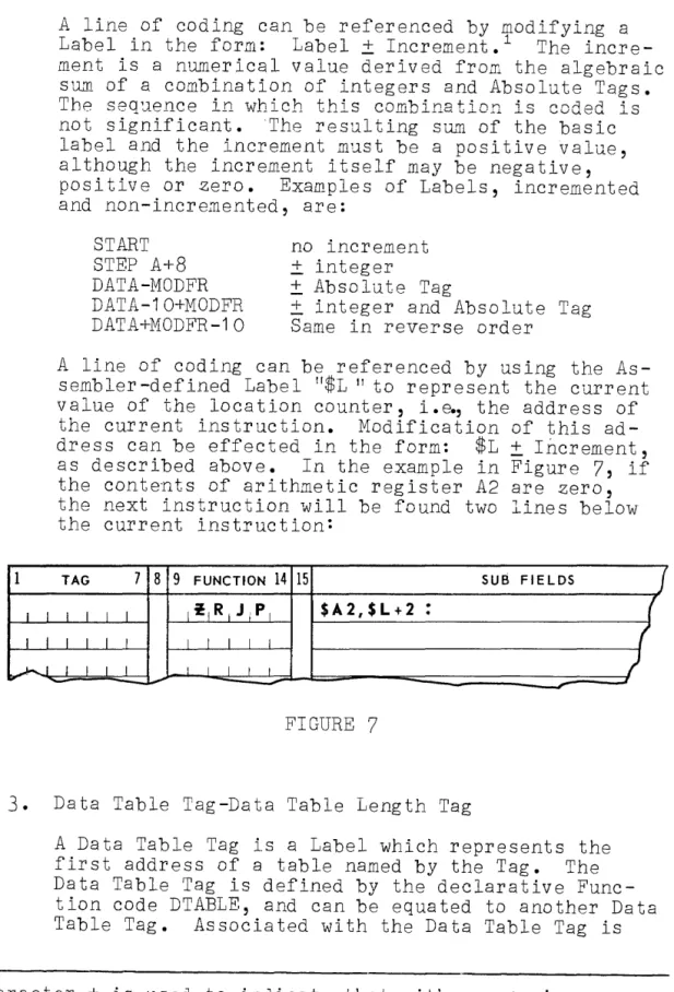
C. Program Structure
A program may consist of one or more segments. Each
segment of a program consists normally of an instruction, area, and a data area, in opposite banks of core stor-age.
Data tables, primarily defined for ROC type programs,
are included in the data area. A data table is a group
of data words which may be considered by the program as an entity. Each entry within a data table bears a fixed relationship to the first entry and may be referenced
via this first,entry. Each data table is independent of
any other except when specified to begin at the same
lo-cation as another. The data tables, although they may
be included within anyone segment, are common to all segments of a program and may be referenced by any seg-ment.
For ROC type programs each data table is modifiable in
length at load time. A length tag is given to the table,
and a minimum length is assigned during assembly. At
load time a new length can be specified, depending on the particular data to be operated upon during the run.
Figure 2 illustrates the most complex form of program.
Note that data table number
4
has been specified tobe-gin at the same location as data table number 2.
EXEC ROC
EXECUTIVE SYSTEM INCLUDING CLAMP AND I/O
FUNCTIONAL ROUTINES
/'
/' / '
SYSTEM FLOW CHART
/ ' / '
/ ' / '
SLEUTH ASSEMBLER
/
/ '
CLAMP DIRECT ROC RELATIVE LOAD
ROUTINE
FIGURE 1 SLEUTH
3
LISTING
CLAMP AOC LOAD
SEGMENT SEGMENT
# 1
#2
1
BANK A
BANK B
I
#1
#2
PROGRAM STRUCTURE
SEGMENT
#3
#3
SEGMENT - - - r - - - .
1 1
1
I
I
1-
----II
#n
- - - , " " - - - - . . . 1
~
-~
-I ,
-I t
I t
I # 2 t
t I
1 I
1 _ _ _ - _ _ _ _ _ ,
#4
' _ . 1
-G]
#3---
---FIGURE 2
SLEUTH 4
DBANK AREA
DTA8LE AR A
INSTRUCTION AREA
t 3:HllDIJI
J
-
I---I--- - - - 1
I---I - - - .---.-.
I - - - . . .
-
---.~-I--- . .. .
-I - - - . . . . .
I
-I--- .~--- . . .
-1 - - - . .
-I - - - . -...
I---I - - - . - - - . - - - ..
-I - - - . -.-- ---.-.--.----.-- .---
.----.---I - - - . . . . ... . . -1 - - - _ . - - - . ---.---.--.--.. - - . - - - . - .
I - - - . . . . . . . .
1 _ . _ . _ .
-I - - - - . .
-I - - - .. .. . . . . . ... . .
-I - - - -.---- - .. ---.--- ... ... . .... ..
-I--- ----.--- .----.--.--
-.---.----.----.---.---S1.N3WWOJ L£ sa131:J 8ns
S3~"d-- :!O - -3~Vd 31.Va ~3WW't~~Q~d
W~O:l ~NlaOJ ~3'8W3SSY
La.,.,
@OVJ\INnI I I I I
--'--'--11--1-
r-rrT--I-I-T-T~
- ' - 1 - 1 ' - 1 - \
l
----r-r----r--r-I---T1-r--r ..
TI TI TI T T - ~~i-r--r"-I
'-,---r--r-r-T--I '-,---r--r-r-T--I I I I
I----r:---r--r
--,----l-'·-:---r-r
I---r--r-',T-r
I I I
--r-r I I
I T I L i l l
I I I
i l l I I I
~-T'I'II
- i l I I I I
- T - - r l - r l l ---rT--, I
I ' l l I I I
IT""" I I I .,.
IT·-....-.--r.-h'-T-TII--T
'iT--iT-r--1
t-r.---...-r-T·-I--,.---r---r--
r--~
-l---II-r r-I I I T--r
I----r-r--r-r--i--r-T-r-
T'-I T'-I
--T
r--r----r ]ITr ..
-[
ITrr ,
-
,-r--T-'-r-T----r-II"-I--'
I--l~ I I
r-
--,T--,T--i-~Trrl-l
L-r
-T-T--r--i-T- r r--r-T
-T-~i-r-Ir-II
L1'\~-
r -,,-T~T ~
-II-.-r---T p
[I:I
~TT' ,-
ul
I I I I I I
-lrl~IT-i r Tr' I
-r-i r -r-i l l - r 1 1 1 1 - .
rrlr'r .•
-11'---'
-T-r--.--r---, ...r-- T r r -I
r-
~IIT-I-'r-SI I vI NQI1.JNn:J 61 81l ~v~
WVM~OMd
NOI!'W'I0410:> ONYI A,.I •• t to NOI';'.IO
-II. ASSEMBLY LANGUAGE FORMAT AND SYMBOLOGY
A. Coding Form
Programs to be written with the SLEUTH Assembly System will be coded on the UNIVAC 1107 Assembler Coding Form.
Figure 3 is a reproduction of this form.
The form is divided into
4
major headings: Tag, Function,Sub-fields, and Comments.
1. Tag field: The Tag field can be blank, or coded with
a Tag or Label. The coded Tag will be defined by the
instruction, and should therefore appear once, and
once only, in the Tag field. A method of protecting
against accidental duplication of tags is described in Section VIII.
A Tag or Label can be written anywhere in the Tag field; right or left justification is not required. Blank spaces are ignored by the Assembler; the follow-ing codfollow-ing of Tags will generate the same value:
XYZM/j. /j.XYZM /j.X/j.Y/j. Z
20 Function field: The Function field will contain one
of the Function codes described in Section III.
3.
Sub-fields: The Sub-fields represent the dataneces-sary to describe the objective of the Function code: what is to be acted upon and how.
Each of the sub-fields must be separated by a comma,
except where specified otherwise in context. For
each Function, the order of fields is fixed.
How-ever, for many Functions, the use of certain
sub-fields may be unnecessary or optional. For example,
indexing mayor may not be desired. The following
rules must be observed when omitting fields from the coding:
a. To omit any field(s) from the right, the field(s)
and the preceding comma(s) should be omitted.
b. To omit other fields, while preserving the order,
only the separating commas are coded.
Co For a sub-field within an instruction which re-q~ires that it be coded, any number of + or -signs may be coded in the field to inform the Assembler that the omission of meaningful coding
is intentional. The field will then be
gener-ated as zeros, without causing SLEUTH to print an error indication.
4.
Comments: Any line of coding may have a shortdes-criptive comment associated with it. Any of the FIELDATA characters can be used., The COlMlents can
start at any point after the colon. A line of
coding can consist of a Comment only, to separate
and identify portions of the program. A blank line,
for spacing, is a valid use of this application.
B. Number and Symbol Representation
Numbers and symbols are represented in SLEUTH source code as combinations of the characters of the standard FIELDATA set shown in Appendix A.
1. Numbers
Numbers may be coded in decimal or octal notation. Either form may be written whenever an integer value
is to be coded. SLEUTH will not accept direct coding of binary numbers.
Decimal integers are coded with any combination of the decimal digits 0 to
9.
Octal integers are coded with any combination of the
octal digits 0 to
7,
and are identified as octal byprefixing them with a dollar sign.
Rational decimal numbers, written with either an ac-tual or implied decimal point, are used in the gene-ration of floating point, and of fixed point scaled who le number s •
Examples of numerical coding are given below, as they might appear in the sub-fields portion of a cod-ing line:
1357986 +1357986 - $246753
-99,$32 9986.243,2 998,-2,7
Positive decimal integer Positive decimal integer
Negative octal integer Mixed half words
Floating point number Fixed point scaled number
A negative number must be preceded by a - sign. A positive number may be preceded by a + sign, or left
unsigned. When a sign is specified, the magnitude of
the generated field is checked by SLEUTH to insure
that a position is available for the sign bit. If
no sign is specified, no check is made. This becomes
especially important in the generation of fractional words, which will be discussed in detail in Section
IVo See Figure
4.
CODED GENERATED CHECKED RESULT
31 or $37 011 111 No OK
+31 or 437 011 111 Yes OK
32 or $40 100 000 No OK
+32 or 440 100 000 Yes Error
FIGURE 4
2. Symbols
A symbol is some combination of from one to six
al-phabetic (A to Z) and numerical (0 to 9) characters.
Each symbol must contain at least one alphabetic character.
Some symbols are internally defined by SLEUTH, or by other System components, e.g., Designators, while others are the inventions of the programmer, e.g.,
Tags and Labels. Symbols defined by SLEUTH are
pre-fixed with a dollar Sign, and a list of these given in Appendix E.
Symbols can appear in the Tag, Function, or
Sub-fields areas of the coding line. Examples of various
symbols are given below:
CONST2 Programmer defined symbol
CONST3
"
"
"
DATA2A
"
!l"
A45B
"
"
"
1234K
"
"
"
N5
"
"
"
EXIT
"
"
"
K
"
"
"
ADD Mnemonic Function Code
EQU Assembler defined Function code
$A3
"
IIDesignator
$L
"
"
Current address TagIII. COMPONENTS OF A LINE OF CODING
A. General Description
A lin2 of coding is a coxplete source language statement. It illSY be an instr1J.cticn, a data definitiorl, a
communica-tion with the Asse~bler, with the Executive System, etc ••
There Iust be an entry in the F~nction field for each
line of coding, ex~ept where the line consists sDlely of
COITEents; entries in any of the other fields ~ay or may not be required.
The instruction portion of the line of coding is termi-nated by a colon (:), wbich illay be coded at any point after the la s t coded fie ld. Even wbere no sub -fie lds are required, the colon illust still be coded.
Following the colon, a comment explaining the line of
coding may be wTitten. Any FIELDATA characters which can
be printed are acceptable, including a blank space (coded
as D. or uncoded), and the colon. The latter, having
pre-viously served its purpose as an instruction terminator, becomes just another character in the comments field. A line of coding is not limited in length to a single
line of the coding form, but may be extended by indenting
the next, and subsequent, lines by at least
15
spaces.Any line may be prefixed by an asterisk (*). Such lines
can be optionally either included in the assembly, or eliminated as explained in Section VII.
The fields and sub-fields which comprise a line of coding are made up of various components, which can be classi-fied as:
Act ua 1 Val ue s
Special Characters Function Codes Tags and Labels Des ig na to r s
B. Actual Values
An actual value is a true, signed, numerical q~antity,
and can be coded as a decimal or octal intege~ a
float-ing point decimal, or a fixed point scaled number.
C. Special Characters
FIELDATA characters other than letters and numbers are
called Special Characters. They can be punctuation
marks, mathematical symbols, symbolic abbreviations,
or non-printing Typew"riter Operations. A list of these characters is given below, with a brief note about their
use in coding. A more detailed explanation for each
will be given in context. Special characters not shown
here serve no special purpose in programming but may be used as part of the comments.
1. Punctuation marks: Colon
Comma
Di t to mark Parentheses Slash
Asterisk
"
( )!
*
Instruction Termination Separator
Function code repetition Separator
Separator
Instruction Deletion or h- and i-field incrementation
2. Mathematical Symbols:
Plus Minus Equals
+
=
Positive sign or Tag modification Negative sign or Tag modification Equality
3. Symbolic Abbreviations:
Blank
Dollar Sign
Blank Space
Octal number and Designator Identifier
4. Typewriter Operations:
(Octal Codes) 00 Master Space
01 Upper Case
02 Lower Case
03 Tab
04 Carriage Return
05 Space
77
BackspaceD. Function Codes
The Function code is the primary operator of each line of coding, and must invariably be present in each line, except as previously noted.
A ditto mark (") coded in the Function code field can be used to eliminate repetitive coding of the same instruc-t ion. See Fig ur e
5 .
1 TAG 7 8 9 FUNCTION 14 15 SUB FIELDS
(
,SI T,~, I , SUM
·
)I L I I I L
·
I I I I I I I ,
..
I I I ,SUM+l·
·
..
,SUM+2·
I I I I I I I I I I I
·
_I1 ~ I I I L ! 1 1 L J
)
-
-
~ /-
-
-
-
-FIGURE
5
There are three types of Function codes discussed in this manual:
1. Hardw'are: These are mnemonic, symbolic equivalents
of the machine functions. They may also be coded as
octal integers, if desired. A complete list of these
codes w'ill be found in Appendix B.
2. Software: These are Assembler defined operations,
some of which will generate words in the object pro-gram, w'hile others prov ide ins truc t ions to the
As-sembler. A complete list of these codes will be
found in Appendix C.
3. Macro-instructions and Subroutine Generatives: These
are either system or programmer defined macro-instruc-tions, or subroutine-generative instrucmacro-instruc-tions, and will
be discussed in Sections VI and
XIV.
E. Tags and Labels
A Tag is a symbol, not to exceed 6 characters which is defined by the programmer, the Assembler, or other
sys-tem components. The use of Tags is not restricted to
the Tag field; they can also appear in any of the vari-able sub-fields.
Each Tag symbol should be unique. However, since it is
possible that duplication of symbols may inadvertently occur - for instance, in a problem which is being
writ-ten by two or more prograffilliers - a procedure is provided to prevent such accidental duplication from destroying
the assembly. This procedure will be disc~ssed in
Sec-tion VIII.
Tags are classified by SLEUTH by the method employed in defining them, and special names are used to describe each type of Tag.
Absolute Tag Label
Data Table Tag
Data Table Length Tag Drum Table Tag
Drum Table Length Tag Segment Length Tag System Tag
I/O Channel Tag I/O Access Word Tag I/O Uni t Tag
1 0 Absolute Tag
1
An Absolute Tag is a symbol which represents an
ac-tual value. It can also be equated to another
Ab-solute Tag. Before any reference to an Absolute Tag
can be made, it must have been previously defined. Each value is a signed quantity, with a maximum
value of 223_1. In the example in Figure 6, MAXM is an Absolute Tag which the instruction equates to
50000.
TOPS is also an Absolute Tag which is equatedto the previously defined Absolute Tag MAXM.
TAG 7 8 9 FUNCTION 14 15 SUB FIELDS
f
,M,A'XIMI I I EIQ,U1 I Sctctaf1
·
•
J
,T,O,PI SI ,
,E,Q,U,
, MAXM·
·
/
I I I I I , I I I I I
(
L
.
~"""'_l...l .1 ... - -I
.."
-
--FIGURE 6
2. Label
A Tag appearing as the symbolic address of a word in the Instruction or Data area of storage is called a
Label. It alw~ys represents a 16-bit positive value
which is the absolute or relative location of the as-sociated word.
1
I I I I
~J
A line of coding can be referenced by modifying a
Label in the form: Label ± Increment.1 The
incre-ment is a numerical value derived from the algebraic sum of a combination of integers and Absolute Tags. The seq~J_ence in "which this combina tion is coded is not s ignif icant • The resul ting sunl of the bas ic label and the increment must be a positive value, although the increment itself may be negative,
positive or zero. Examples of Labels, incremented
and non-incremented, are: START
STEP A+8 DATA-MODFR DATA-10+MODFR DATA+MODFR-10
no increment
± integer
±
Absolute Tag±
integer and Absolute TagSame in reverse order
A line of coding can be referenced by using the As-sembler-defined Label "$L" to represent the current
value of the location counter, i.e~ the address of
the current instruction. Modification of this
ad-dress can be effected in the form: $L
±
Increment,as described above. In the example in Figure
7,
ifthe contents of arithmetic register A2 are zero, the next instruction will be found two lines below the current instruction:
TAG 7 8 9 FUNCTION 14 15 SUB FIELDS
J
I~IR, JjP1 $A2,$L+2
.
(
I I I I
.
I I J 1 1 I I I I
(
I I 1 1 1 1 1 I I
)
_1.,...00'"
-FIGURE
7
3. Data Table Tag-Data Table Length Tag
A Data Table Tag is a Label which represents the
first address of a table named by the Tag. The
Data Table Tag is defined by the declarative Func-tion code DTABLE, and can be equated to another Data
Table Tag. Associated with the Data Table Tag is
lThe character ± is used to indicate that either a + sign or a
- sign may be used in the coding, but the combination
±
cannever be coded.
the Data Table Length Tag, which represents the num-ber of storage locations required to contain the
table. The length is defined by equating the Tag to
an actual value or Absolute Tag.
The uses of these Tags will be explained more fully in the discussion of the DTABLE instruction in Sec-t ion V •
4.
Dr~~ Table Tags - Drum Table Length TagsThese Tags are similar to the Data Table and Data Table Length Tags, except for the fact that the
storage medium is the magnetic drum rather than core. A further explanation will be found in the discussion on the MDT instruction in Section V.
5.
Segment Length TagThe IBANK and DBANK instructions (see Section V) provide for the coding and definition of Segment
Length Tags. The Assembler counts the number of
generated words in each segment, and assigns that
value to the Segment Length Tag. The programmer
must never assign a value to a Segment Length Tag. It is coded with the same form as a Label.
6. System Tag
A set of System Tags, defined jointly by SLEUTH and the Executive System, is used in communications be-tween the object program and the Executive System.
System Tags must never be defined by a program.
Ab-solJ_te outP'.lt progra:ns, running independent ly of the ROC Load and Executive Systems, must never use
Sys-tem Tags.
7.
Input/Output (I/O)Channel TagsA symbol of
5
characters or less can be assignedas an I/O Channel Tag. It provides a 4-bit value
for an a-field channel designation in AOC or DIRECT
ROC type programs. Channel Tags are not required
for EXEC ROC type programs, but may be used if it is desired to refer to the channel.
Further information on the uses of Channel Tags will be found in the discussion of Input/Output, Section XII.
8.
I/O Access Word TagThe I/O Access Word Tag is the sy~bolic address of
the input, or outp~t, access control word
correspond-ing to the I/O Channel Tag= It is ~sed for Absolute
and ROC Direct programs only.
The I/O Access Word Tag is defined internally by SLE0TH, and no programmed definition is required. For each Channel Tag, SLE0TH provides an Input Access Word Tag and an Output Access Word Tag, identified
symbolically by an I or 0 prefix to the Channel Tag.
Modification of Access Word Tags is not acceptable. Further information on the uses of Access Word Tags will be found in the discussion of Input/Output
rou-tines, Section XII.
9. I/O Unit Tag
The I/O Unit Tag is a symbol representing an I/O
Unit. Further information on the uses of Unit Tags
will be found in the dis c us s ion 0 fIn put
/0
u t put r 0 u -tines, Section XII.F • Des ig na tor s
A Designator is an Assembler derined ~ag, and is the
symbolic address of a special register, or a special
in-dicator value. There are two types: a-type Designators,
and j-type Designators.
1. a-type Designators
An a-type Designator is defined as the symbolic ad-dress of one of the special registers of the thin-film memory. It can be coded in the a or b sub-fields of an instruction, and will generate a 4-bit value in the corresponding field of the machine word. It can also be coded in the u-field, and in this
case will generate a 16-bit octal address.
The programmer may equate a Tag to an a-type
De-signator. The coded Tag would represent the
Desig-nator throughout the program. A single change in
the definition of the Tag would have the effect of changing each reference to the special register.
A table of a-type Designators is given in Figure
8.
DESIGNATOR VALUE REFERENCE
Decimal Decima 1 Octal
$B0 0 0 Unassigned 2
$B1 -$B1 5 1-15 1-1 7 B Registers
$A0-$A 1 5 12-27 14-33 A Registers
$Q0-$Q3 12-15 14-1 7 Q Registers 3
$R0 64 100 Real Time Clock
$R1 65 1 01 Repeat Counter
$R2 66 102 M Register
$R3 67 103 T Register
$R4-$R15 68-79 1 04-11 7 R Registers
FIGURE 8
2. j-type Designators
A j-type Designator is a symbol representing the ap-propriate value of the j-field of an instruction. It should be used only as the representation of the j-field value, and never as a tag representing some
other field. A 4-bit value is always generated.
A table of j-type Designators is given in Figure
9.
DESIGNATOR VALUE REFERENCE
Decimal Decimal Octal
$w 0 0 Whole word
$H1 -$H2 2-1 2-1 Half words
$XH1 -$XH2 4-3 4-3 Half words with sign extension
$T1 -$T3 7-5 7-5 Third words
$S1 -$S6 13-8 1 5-10 Sixth words
$UOp 14 16 U -field is act ua lop era nd
$XUOp 1 5 1 7 Same, with sign extension
.
FIGURE
9
2Becomes one of the B Registers with BTR, LBM, TMO instructions.
It is always a legitimate designator for location
0
of filmme-mory.
3Ihe Q Registers are the
4
overlapping A and B Registers.IV. MACHINE AND GENERATIVE INSTRUCTIONS
A. Machine Instructions
1
The general coding format for a machine instruction word
is shown in Figure 10. The use of each of the fields
will be explained below.
TAG 7 8 9 FUNCTION 14 15 SUB FIELDS
.
I 1 1 t 1 I I I I f I J I a,u,b,i
.
I
_.1
I I I I I I I I I I
I I I I I I I I I I ~
-
-FIGURE 10
1. Tag (t)
The Tag, if coded, is a Label, and is the symbolic address of the line of coding.
2 • F unc t ion cod e (f)
The function code is any appropriate function code
of the machine instruction repertoire, Appendix B.
One Assembler-defined Function - JUMP- can also be
considered as a machine instruction. It is
equiva-lent to a CSJP instruction, with an a-field value of zero.
3. Special Registers (a)
The a-field normally represents the film memory special register involved in a machine operation. It can be coded with a decimal or octal integer, an Absolute Tag, or most frequently with an a-type
De-signator. The reference can be to any of the A, B,
Q,
or R registers as determined by the Function code.If a Designa tor is coded w'hich is not of the set
called for by the Function code - for exa~ple, a LDB
instruction to be performed in register A1 - the Assem-bler will attempt to generate a valid a-field value, w'hich mayor may not be the value intended by the
1 TAG 7 8
I I I L I I I I I I I I IL IALB~EIL IA
programmer. If a valid value cannot be generated,
an error warning will be printed.
In the examples in Figure 11, the comments refer to the a-field coding.
9 FUNCTION 14 15 SUB FIELDS 37 COMMENTS
IJ I U MI PI , EXIT :UNCODED
IC I S I JI PI I,l', E X IT : lERO CODING (SAME AS JUMP) IS lUI BI I $A3,LOCA : DESIGNATOR FOR A-REGISTER
/
(
I
I I I I I I IL 10 1 BI I $B2 CONST : DESIGNATOR FOR B-REGISTER I I I I I I I IL 101 RI I $R15,99,,$UOP : DESIGNATOR FOR R-REGISTER I I I I I I IAI 0 1 0 1 I $Q2,ITEM : DESIGNATOR FOR Q-REGISTER I I I I I I IS I TI PI I COUNT,TOTAL : ABSOLUTE TAG
I I I I I I ILl 01 PI I 13 DATE : DECIMAL INTEGER = A1 I I I L I I ILl DIP I I $15 DATA : OCTAL INTEGER = A1
I I I I I I ILl DIB I I $Al,DATA+5 :A1 =13=B13.GENERATED AS 13 I I I I I I ILIDIP I I $B12,CONSTB :B12=12=AI,l'. GENERATEDASI,l' I I I I I I ILID I81 I $Q2,XY~ :Q2=14=B14. GENERATED AS 14 I I I I I I IAID ID I I $Q2,WXYl: : Q2 = 14 = A2. GENERATED AS 2 I I I I I I IL I DIP I I $B3,ABC : B3 = 3 = A? ERROR WARNING
I I I I I I I I I I I :
I I I I I I I I I I I t-... :
---
-
----
-
-FIGURE 11
4.
Operand field eu)The u-field serves a variety of purposes and the method of coding is dependent upon the application:
Operand address Absolute operand Next instruction Shift count
Memory lockout indicator Indirect addressing
SLEUTH 18
\
I
(
J
/
'\
I
a. Operand Address
In this application the coding in the u-field represents the address at which the data to be
operated on will be found. It can be coded as
a Label, to represent a core address, or as an a-type Designator, to represent a film memory
address. Either type of coding can be modified
as described in Section III, paragraph E.2 ..
For Absolute or ROC Direct output programs, an
octal or jecimal integer may be coded. A
16-bit value is generated in all operand address applications.
b. Absolute Operand
When the j-field is $n octal 16 or 1~ i.e.,
coded with Designator $UOP or $XUOP, the value
entered in the u-field becomes the actual
oper-and, and not the address of the operand. It is
coded as an octal or decimal integer, or a
pre-viously defined Absolute Tag. An 18-bit value
is generated.
Another method of generating an actual value in the u-field is by coding a literal expression. This method can be used when the desired value is a floating point, or fixed point scaled num-ber, or an integer value requiring more than 18 binary places. An Absolute Tag may also be used.
A literal expression consists of two parts: the
appropriate numerical generative Function code (see paragraph C), and the required value,
separated by a comma. The entire expression is
enclosed within parentheses.
Words are generated for each literal expression, and are added to the end of the DBANK area being generated, without duplication.
c. Next Instruction
In jump type instructions, the u-field represents the core memory address which contains the next
instruction. Coding is the same as for an
oper-and address.
8 9 FUNCTION 14 15
\ ILID ,R I I
~L1DIBI I
( IMjP III I ,S I TIP I I
I
I LI DIP I I ILl DIP I If
ILl DIP I I ILl DIP I I \ ILIDIBI I
)
IS I TIP I I INI ~I J IPII lS~CIS,HI
( ILIMIL IRI
t
I S I U,B I I,
~SlUIBII
J I S I UIB I I
( IS I UIB I I
L-
-"-l.~ J.d. Shift Count
In all shifting instructions except Scale Factor Shift (SFSH), the u-field represents the number of binary places to be shifted. This shift count should not exceed 72 places, and is coded as a decimal or octal integer, or an Absolute Tag.
e. Memory Lockout Indicator
A knowledge of the manner in which this instruc-tion operates is essential to an understanding
of the following explanation. A review of
chapter 12 of the UNIVAC 1107 Technical Bulletin
UT
2463,
Central Computer, is recommended.The u-field of this instruction requires four groups of 4-bi t -nu.mbers. Wr i te out the four groups in binary, then convert to an octal
for-mat. For example, if the desired values are
3,
0, 13, and 9, write in binary:
0011 0000 11 01 1 001
The conversion to an octal format will give the coding
$3033
1 , which is the absolute value to becoded in the u-field. An Absolute Tag can also
be coded.
SUB FIELDS 37 COMMENTS
\
$R6,MAXM : LABEL
$B3,DATA+S : LABEL, MODIFIED
/
$A3,$A3 : A- TYP E DESIGNA TO R
I
$AS,$714S : ABSOLUTE ADDRESS
$A4,144(1(1,,$UOP : DECIMAL ABSOLUTE OPERAND
,
$A7,$17777,,$UOP : OCTAL ABSOLUTE OPERAND
$A7,MASK,,$UOP : ABSOLUTE TAG OPERAND
$A6,(WF,6.28,-6) : FLOATING POINT LITERAL
$B2,(W,$17777) : OCTAL LITERAL \
$A3,(W,MASK) : ABSOLUTE TAG LITERAL
$A2,$L-S : NI =MODIFIED CURRENT ADDRESS
$A 3, 3 : SHI FT COUNT I
,$30331 : MEMORY LOCKOUT PARAMETERS f
$AS,*ADDR+S : INDI RECT ADDRESSING
$AS,ADDR*+S :
..
..
\$AS,ADDR+*S :
..
"$AS,ADD R+S* :
..
":
--
-
- )----
---
--.,- ...(
~
~
f. Indirect Addressing
I nd ir e c t add res sing (s e t t i ng the i - fie ld t 0 1 ) is effected by coding an asterisk either before
or after any element of the entry in the u-field~
g. Examples of the above applications are given in
Figure 12:
5 • I nd ex Reg is t e r s (b)
The b-field specifies one of the B-Registers used
for indexing purposes. It is coded with a decimal
or octal integer, an Absolute Tag, or an a-type
De-signator. Only $A0-$A3, $Q0-$Q3, and $B1-$B15 are
valid Designators.
B-Register incrementation (setting the h-field to 1 ) is effected by coding an asterisk before or after the entry in the b-field.
Examples of b-field coding are given in Figure 13:
8 9 FUNCTION 14 15 SUB FIELDS 37 COMMENTS
I
! IL 10 , P, I $A2,ITEM, $B111 : A·TYPE DESIGNATORI
ILIDI PI I $A2.ITEM.$12 : OCTAL ABSOLUTE ADDRESS \
ILIDI PI , $A2ITEM.IDXA : ABSOLUTE TAG )
I SIT I PI I $A3,OUTPUT ,*$B5 : B·REGISTER INCREMENTATIO,",
lSI T I PI I $A3,OUTPUT,$BS* :
..
..
I
: 1
I I I I I \
, I ' I : )
(.1 I I I I I
-V ~
FIGURE 13
6. Operand Interpretation (j)
The j-field is coded with a decimal or octal integer,
an Absolute Tag, or a j-type Designator. No coding
is required where the j-fiBld is the minor Function code, i.e., where the Function is a 4-letter mnemonic
code. In this case SLEUTH a~tomatically assigns the
correct value.
Examples of j-field coding are given in Figure 14:
~
9 FUNCTION 14 15 SUB FIE LOS 37 COMMENTS)
I LID, Pi I $A3,WORDII$Hl : LOAD LEFT HALF
I LID, P, I $A4,WORD,,$H2 : LOAD RIGH T HAL F
)
I AIDI 01 I $A5,3gg ,,$UOP : U IS ABSOLUTE OPERAND
f
I!, R, J, P, $R15,BEGIN : NOT REQUIRED 1
·
J
, I I I I
·
)
-
-
--
·
rL~
-
---
-
-FIGURE 14
B. Generative Instructions
In general, generative instructions are defined as those
instructions which generate one or more word~ in the
ob-ject program. The following types of instructions are
classified as generatives: Numerical word generatives Character code generative Block reservation generative Macro-instruction generatives Library Subroutine generatives Input/Output instructions
Macro-instructions, Library Subroutines, and Input/Output will be discussed in separate Seations.
1. Numerical Word Generatives
SLEUTH provides a set of software function codes which are used to define and generate whole or
par-tial numerical words. The coding line consists of
a Tag (optional), Function code, and a varying nQTI-ber of sub-fields as determined by the Function code.
a. Whole Word Generation
(1 ) The F unc t ion cod e W will gene rat e a 3 6 ~ bit
signed numerical word. The single
sub-field can be coded with a decimal or octal
integer, an Ab~olute Tag, or any sYIbolic
coding which represents a nUlerical value.
(2) The Function code WF will generate a
Float-ing Point number. Tw'o independent ly signed
sub-fields are required: a rational decimal value, followed by a decimal exponent,
se-parated by a comma. If the exponent is zero,
it can be omitted, and only the value need be coded.
(3) The Function code
WX
will generate a FixedPoint Scaled number. Three independently
signed sub-fields are required: value, de-cimal exponent, and binary scale factDr. The coding of all three fields should be
de-cimal. In the examples of the
WX
instruc-tion in figure 15, the same value will be
generated for all three forms. The exponent
and/or the scale factor may be omitted if they are zero values.
b. Partial Word Generation
(1) The Function code H will generate two 18-bit
values into a single word. Each half-word
is generated, and can be signed, independent-ly, and can be coded as a decimal or octal integer, an Absolute Tag, an a-type Desig-nator, or any symbolic coding which
repre-sents a numerical value. The value of each
generated half-word must not exceed 18 binary bi t s •
(2) The Function code T will generate three
12-bit values into a single word. Each
third-word is generated, and can be signed, in-dependently, and can be coded as a decimal or octal integer, an Absolute Tag, or an
a-type Designator. The value of each
gener-ated third-word must not exceed 12 binary
bits.
(3) The Function code S will generate six 6-bit
values into a single word. Each sixth-word is
generated, and can be signed, independently, and can be coded as a decimal or octal
in-teger, an Absolute Tag, or an a-type
DeSigna-tor. The value of each generated sixth-word
must not exceed 6 binary bits.
1 TAG 7 8
,L,I,Md~T,
,C,O,N,S,T, ,D,A,T,A[ , ,D,R,M,D,A,T IF/PrN,O,A, ,F,P ,1'4,01 B, ,F,X,P,S,CIA IF,X'PISIC,B ,F,XIP,SIC,c IIID,X,W,D' ,W,o, R,D ,A, ,W,O,R~D~B , ,W,O,R,D,C, ,3 ,WI DI', , ,31 W, D,2, 1
13 IW, D13, J
,6 IW, O,R ,D, ,V,A,R,ljB,L , , I I, ~ ,
I 1 , I I I
(4) The Variable Bit Field Function code G will
generate a number of fields of varying lengths
into a single word. Each variable field
con-sists of two parts: the value to be
gener-ated, and the size of the field in binary
bits. The two parts are separated by a slash,
and commas separate one field from another.
9 FUNCTION 14 15
I IW I , ,WI I I ' 1 W, I ~ , ,WI , , , ,WI FI / , ,WI F, , I ,WI XI , , IW, X, I
1 ,W, XI I
I I H, , ,
The desired value of each field is coded as a decimal or octal integer, an Absolute Tag, an a-type Designator, or any symbolic coding which represents a numer ical value.
A total of
36
binary places must be accountedfor, therefore a zero field of the required size must be coded at some position of the word, if necessary.
Examples of nlliTIerical word generation are
given in Figure
15.
SUB FIELDS 37 COMMENTS
14411g : POSITIVE DECIMAL INTEGER
-$1357 : NEGA TfVE OCTAL INTEGER
ABC : ABSOLUTE TAG
DRMADD : DRUM ADDRESS
6.28 -6 : FLOATING POINT NUMBER
- 29.33 : NEGATI¥E VALUE, g EXPONENT 9.98, 7 : FIXED POINT SCALED NUMBER
998-27 : SAME VALUE
.998 1 7 : SAME VALUE
1 (I : DECIMAL HALF·WORDS
/
-~I
I
) ~ )\
{, ,HI , , 14982 -$7435 : DECIMAL AND 0'-TA1 HAL F·WORDS ,
, ,H, , , ABSTAG-5,+25 : MODIFIED ABS. TAG AND DECIMAL )
, ,H, ' , 15,ADDR+5 : DECIMAL AND CORE ADDRESS
I , T i l , $A5,72,-16 : THIRD·WORDS
1 , T i l l -6,$35,NINE : " "
,
J ,T, J 1 11117,511,11 :
..
" )1 ~ SI ~ ~ $77,$A5, 19, TAGG,-5,/l : SIXTH·WO RDS
I
, IG , fJ/2 , V A LUll 6, $ 31/8, $ A 2 14, (I I I , 3916 : VARIABLE BIT FIELDS
\
1 1 1 :
v---
-~ ~... : . /
-FIGURE
15
I TAG
I I I I , I ,W,AIR,N,GI
I I , I I I
I , , I I I
v-7 8
2. Character Code Generative
The Character Code Generation Function code SC will generate a word containing six FIELDATA characters. The first sub-field of the instruction is coded with a decimal integer to designate the number of words to be genera ted; a maximum. of 10 words can be
gener-ated with anyone SC instruction. Starting with the
left-most character following the separating comma, six 6-bit fields from the successive groups of six written characters form the generated wordso
Any of the FIELDATA characters, including those which normally serve a definite purpose in the
cod-ing, such as the colon, dollar sign, comma, etc.
can be usede A blank space is a valid character
with this Function code, and must be considered when forming the 6-character groups.
Examples of the SC instruction are given in Figure 16:
9 FUNCTION 14 15 SUB FIELDS 37 COMMENTS
I ,S IC I ~ 3,ASl1SIMPLEl1ASl1THIS :
I IS IC I I 1Q' NOTE: AMAXIMUM OF TEN 6 • C H A R A c=r E R W 0 R 0 S CAN BEG ENE RAT E 0 W I I IS IC I I .. TH ONE SC INSTRUCTION :
I I I I I :
' - - -
-
--
-
: ~'--FIGURE 16
3.
Block ReservationThe FLlnction code RESV w'ill reserve a block of words. The Label in the Tag field is the address of the
first word of the reserved block. The sub-field may
be coded as a decimal or octal integer, or as an Ab-so lute Tag
±
an increment, and is the nun-iber .of word sto be generated as zeros and reserved. This
instruc-tion can be used at any point where word generainstruc-tion is allowed, ie., in either the instruction or data areas of the program.
1
....
Examples of the RESV instruction are given in Figure 17.
TAG 7 8 9 FUNCTION 14 15 SUB FIELDS ISIB1LIOICIK lR1E,S,V1 48
·
·
lTIBILIOICIK I RI EI S I VI $31
·
·
IU1B1LIOIC1K I RI EI S I VI ABSTAG+8
·
·
I I I 1 1 1 I I I I I
-
--... - ~FIGURE 17
SLEUTH 26
(
/
/
J
V. DECLARATIVE INSTRUCTIONS
A. Definition
In general, Declarative instructions are instructions
to the Assembler. They do not normally generate wnrds
in the object program. All Declarative Function codes
are Assembler-defined (software) Functions. See
Appen-dix C.
Declarative instructions can be classified in the follow-ing categories:
Program Specification Equali ty
Segmenting
Table Definitions (core and drum) List Spacing Instructions
Selective Jump Switch Definitions Macro-Instruction Definition
Input/Output Definition
Macro-instructions and Input/Output are discussed separately in Sections VI and XII respectively.
B. Program Specification
1. The first line of every program must be a PRO
in-~truction. The Tag field of this instruction con-tains the name of the program, and must be left-justified.
The PRO instruction requires one sub-field, which is coded with one of three Assembler-defined sym-bols which specify the object program format:
ABS Absolute Binary (AOC)
DIR ROC Direct I/O (DIRECT ROC)
EXE ROC Executive I/O (EXEC ROC)
The s pecia 1 comment s of this ins tr uc t ion wi 11 be
printed as the heading for each page of the listing,
up to a maximum of 72 characters. A blank space is
considered to be a valid character.
2 • The la s t 1 i ne 0 f cod i ng 0 f eve r Y p,r 0 gram m u s t be an
. ENDPRO instruction. The Tag field is ignored by
SLEUTH. The sub-field is the address at which
exe-cution of the object program is to begin. This
address must be in the instruction area of storage. Examples of the PRO and ENDPRO instructions are given in Figure 18.
1 TAG 7 8 9 FUNCTION 14 15 SUB FIELDS
P,R,O,G, IA\ IPIR 101 I ABS
·
·
P,R1O,GI I BI IPI R 101 I DIR
·
·
PIRIOI G, lei IPI R 101 I EXE
·
·
I I I , I I EINIDIPIRIO BEG I N
·
·
I I I I I I I I I I I
~
-
-
- ~FIGURE 18
/
\
/
(
\
\-3.
The program name is retained in its symbolic formatin the ROC output of the Assembler. The program
name is expanded to a 12-character left-justified representation.
It is used as the program name by both the Executive System and the Relative Load Routine to identify the program, and to indicate the base address of the ROC. For further information see the manuals on the 1107 Executive System and 1107 Relative Load Routine.
c.
EqualityThe "equals" Declarative serves the logical function of defining a Tag by assigning a value to it, or of
re-lating two Tags. The Function field can be coded with
either of two synonymous symbols: EQU or the "equals"
sign (=).
The coding in the sub-field defines the Tag or Label in the Tag field, and may be written as a decimal or octal integer, a Designator, or any type of Tag or Label.
Mo-dification in the form Tag 2 increment is permissible.
The Tag being defined assumes the type of the defining Tag, i.e., a Tag defined by a Data Table Tag also
be-comes a Data Table Tag, etc .•
The "equals" declarative is also used to ,define Tag;s
within other declaratives. In this case it is coded
not in the Function field of the instruction, but in one of the sub-fields, and only the equals sign form
(=) is permitted. A more detailed explanation of the
latter use will be given in context.
1
V' TAG
Exa.TIples of the "equals!! declgrative are given in
Figure 19:
7 8 9 FUNCTION 14 15 SUB FIELDS 37 COMMENTS \
ICIHIAIRILI' [ I EQ U I CHUCK : TAG OR LABEL )
IDISIGIII I I [EIQ [u [ $A 3 : DESIGNATOR { IBlflGlllNI I I E1Q1U I START+16 : LABEL + INCREMENT \ I C I 01 NI SIT [ X I I EIQ 10 I -48 : INTEGER /
ICI~NIS, TIX I I I = I I -48 :
..
~I TI ~ BI LI C I D,TIA[BILI E =TABLA,LGTHC=CONST+42 : = IN SUB-FIELDS {
I I I I I [ I I I I I :
\
---
_ . . 1-
-
-FIGURE 19
D. Segmenting Instructions
Two instructions are available to control the place-ment of words in each bank of storage, and to segplace-ment
the program. These instructions are IEANK, for the
instruction area, and DBANK, for the data area.
A Label coded in the Tag field of an IBANK or DBANK in-struction will have the same effect as if it had been coded in the Tag field of the first machine or genera-tive instruction following the IBANK or DBANK declara-tive.
The format of the sub-field portion of the instruction will depend on whether storage of the segment on tape or drum is required. Where storage is not required, at most a single sub-field will be coded.
For AOe type programs, the sub-field is coded with a decimal or octal integer, or a previously defined Label
or Tag
±
increment specifying the absolute address atwhich the next generated word is to be placed. If the
sub-field is uncoded, the next available address will be assigned.
For ROe type programs, absolute addresses must never be given to segments, and the sub-field is either left uncoded if continuation at the next available address is desired, or is coded symbolically, relative to some previously defined address of the same type of instruc-tion.
TAG 7 8 9 FUNCTION 14 15 SUB FIELDS 37 COMMENTS
~_L_L_L~_~_ _1_1 I I~_~ ~~ __ ~ ____________________ ~ ____ ~ _______ ~~~~~~~~~~~~~~~~~~~~~ r-L~ __ J~_tB_L!l__ _--1J._.L B I A L~L~ c-_$ 3 Q' " _______ . __________ . ____ . __________ . ____ .. : S T A_R_T._=_$_3_Q'_" _ _ _ _ _ _ _ _ _ _ _ _ _ _ --I
__ L_L~_l.-l__ _l'( I E I TIC I ) ' - - - -_____ .. ________ ~~~_. __ ~~~~~--.~~~~~~~~~~~-~-_t
~L.~L~~_ ~~~~ J3~ _____ ~ _______ ~ _ _ _ _ _ _ _ _ _ _ _ _ _ _ _ _ _ _ _ _ _ _ _ _ ~
-.i.~_.L!JAL!LIL__ ~_Jl.~.L!J~_ ~ ____ . __ . ____ ._. __ . _____ ~. : SA __ M_E._E_F_F_E_C_T _ _ _ _ _ _ _ _ _ _ _ _ _ _ -I
-.L_L..L_L_l_.J____ __lLJJ~lAINJ!.. S TAR T : START MUST BE PRt:-DEFINED
llm!mmlmll~mmimm~mmimmj ~.:I.I.I.I.i. :l!iij~mjjjimm~~m!iiiliij~~ijji
·r.f.l.!.!..l . • --- - ---R
-~_·-·_C
__ .... _ .. T _ . -Y .... p .._.-.~
.. _-.. -.. _;. - __;-_~.
_._---_._-= -GRAM
Slmmmlmmmmmmmmmmmmmmmmm~mllllllll!!!mmmllllllll!1111111IIIIIIIIIIIIII!!!!II!II!1111!111!llill!I!II!!111111111l!!l!llllllllillmlllllllllllllllllilimmllllillmmm
... = .... = .... = .... = ... ,,,... .. .... ... ... ... ... .\ I I I I I (f) WS-LT\AI RI TI
t-4
I I I I I
__ LL.LItlA I N I K
.-l( IEITICI)
: ASSEMBLER ASSIGNS NEXT LOCATION
- - - . - - - --.-=-=:....=::....:..-=-=-=~~::...::-=...:...=...:..:....:=..-.::....:-=....:..:...:.-=--=-=.::.-=-:..:...=....:...:.-~----I
t~j I I I I I I
q
1-3 I I I I I I
:::r:: f---L---L---I...--'---..L-~
w ~.\ TIA, RI TI __
a
~.L.-L_L __ L_l __ _
-.Ll_..L_L...L--1. __ _
_
~J!.~1!!!L'!'1~_ ,S IEIGL~~_...-LI I I I .L_
I I I I I I
LLL.-l_l_1--.l __ _
_..L._L~_L __ 1_1 __ _ ~_L.LL~l __ _
I I I I I I
I I I I Li_
I I I I I I
I I I I I I
- L . ..L.L~_
-.L_I ~_
I I I I I I
~~JAL~~
___ I( I EITICI)
w-It BI AI N I K
-L~~ __ -1J _1.I!_L.~ L~l!.
~~.L~~ -1--.L~t.~
I I I i I
w-
I 1 ___ - ' - .,.
f---..l_L
i
"-. I I
I-_L~ I I
I I I I I
I I .1
I I I I I
I I I I I
I I I I 1
I I I I I
: SAME EF FECT
-~---~~--- -~--~~~-~~--~~~~---~
START+8 : RELATIVE LOCATION
J---~~~---.--.---.---..
-~-1----"-' T~A_P_E~Q.L.' __,L_G_T.~I ___ . _______ . __ . _________ : STO _~~~__'E__'O=--N_'_____'_T_A:..:...P_.:::E'____ _ _ _ _ _ _ _ _ _ ---I
,DRUM,LGTHI - - - -~~~-~~~~--=-:..:..::..--::...::...:....=-=-=--=::...=..:-=-=-..:...:..:..-~---I :DRUM STORAGE. DRUM TABLE LENGTH TAG MUST ALSO BE LGTHI
I---~~~--~~~.----.--.---.-~~-~~-~--~-~----=-=-~-~~~~~--The first use of the IBANK or DBANK instruction sets
the location of the. following instruction. The next
use of the same instruction specifies continuation at the next available location following the preceding
section of the same type. To accomplish this, SLEUTH
maintains a pair of IBANK and DBANK "loca tion counters," and increments these as required.
The effect of an IBANK or DBANK instruction is can-celled by the next IBANK, DBANK, or DTABLE
instruc-tion. It is not necessary that all instructions of
the same type be grouped together; an IBANK (and its associated block of instructions) may be followed by a DBANK, then another IBANK, etc ••
For segment s requir ing tha t the load rout ine be dir·ec ted to store the segment on tape or drlliTI, two additional
sub-fields must be coded. The first sub-field is coded as
described in paragraph 1. above. The second sub-field
will specify the tape unit or the drum address, and is coded as a Tape Unit Tag, or a DrlliTI Table Tag. The third sub-field gives the length of the segment and is
coded as a Segment Length Tag. SLEUTH counts the number
of word s genera ted in each segment, and ass igns the ap-propriate value to the Segment Length Tag automatically. It can be referred to for the number of words of the seg-ment.
If drlliTI storage is req~ested, the Dr~~ Table Length Tag and the Segment Length Tag must be coded identically. A further discussion of Segmentation will be found in Section XI.
Examples of the IBANK and DBANK instructions are given in Figure 20.
E. Table Definition
Tables can be stored in core memory, or on the magnetic drum.
1. Core Storage tables
The DTABLE instruction defines a data table for ROC type programs, which is variable in length, in con-trast to the DBANK area which is fixed in length. The Tag field of a DTABLE instruction is a Data
Table Tag, and is the name of the table. It
repre-sents the address of the first word of the table.
There are two s~b-fields associated with this
in-struction. The first sub-field sets the starting
Tag. If this sub-field is uncoded, the assign-ment of the address will be left to the Relative
Load Routine. Coding is required only when it is
desired to equate a data table to a previously de-fined data table, thus making their starting ad-dress the same. The coding consists of an "equals" sign followed by the previously defined Data Table Tag.
An address within a Data Table can be referenced by one of tWD possible methods:
Data Table Tag
±
incrementData Table Tag
±
Data Table Length TagThe combined form: Table Tag
±
increment±
LengthTag is never permitted.
If a Data Table Tag is defined as being equivalent to another Data Table Tag by means of a DTABLE in-struction, both Tags are primary Data Table Tags. If a Tag is equated to a Data Table Tag ± increment by means of an EQU declarative, it is called a
se-condary Data Table Tag. A primary Data Table Tag
can be referenced by either method shown above, but a secondary Data Table is limited to the form:
Tag
±
increment.The second sub-fie ld is the Da ta Table Leng th Tag, and specifies the minimum number of storage
loca-tions required to contain all the words generated
for the table. It is modifiable at load time for
ROC type programs. The following methods of coding
are possible. (blank)
=
Absolute Tag= actual value
Leng th TagLength Tag
=
Absolute TagLength Tag
=
act~al valueIf the field is uncoded, a length of zero will be
specified. If the coding is in the form:
=
Abso-lute Tag or
= actual value, the length will be as
specified by the Absolute Tag or actual value. In all three cases, no modification at load time is possible.
In the other three cases, the mlnlmum length w'ill be as specified by the Absolute Tag or actual value, or zero if no equality is coded, and modi-fication at load time for ROC type programs is possible.
I TAG ITIAIBILIAI
ITIAIBILIBI
ITIAIBILICI
I I I I I I
I IMIDISI I
I JJiJlSI I
I I I I I I I I I I I I
I I I I I I I I I I I I I I , I i '
I I I I I I
v
78
The Data Table Tag and the Data Table Length Tag are retained in the object program in symbolic form for the Relative Load and Executive Systems.
A Data Table may be preset in the same manner as a DBANK area, by coding the data which will comprise
the table immediately following the table definition. Following the last coded data line, an IBANK, DBANK, or DTABLE instruction will signal the end of the current table.
Further information on Data Tables will be found in the discussion of Library Subroutines, Section XIV. Examples of DTABLE instructions are given in Figure 21 •
9 FUNCTION 14 15 SUB FIELDS 37 COMMENTS
I
D,TIA,B,Llc TLGA=6.4 : PRiMARY.DITIAIBILIE , TLGB=CONST+2fi)' : PRIMARY.
1
DITIAIBILIE = TA B LA T LGC : PRIMARY. MIN. LENGTH = fi)'! I I I I :
I EIQIU I I TABLA+18 : SECONDARY
I EIQ,U I I TABLB+24 : SECONDARY I
I I I I I : J
I LID I PI I $A2,TABLA+5 : CORRECT REFERENCE I I LID IP I I SA2. TABLA+TLGA :
..
I I \I
I LID IP I LID p. ;I
$A2,MDS+2 $A2 JJS+TLGB : : INCORRECT " " " II
I I i i i : \
....I--
-
-
....r----
-FIGURE 21
2. Drum Storage Tables
The MDT instruction defines a drum data table for absolute or ROC type programs.
The Tag field of an MDT instruction is a Drum Table
Tag, and is the name of the table. It represents
the address of the first word of the table.
For absolute type programs, the address of the Drum Table Tag may be specified by coding the first sub-field with a decimal or octal integer, or an Absolute
Tag. Or a secondary Drum Table Tag may be equated to
a primary Drum Table Tag by coding the sub-field with the tlequalsl! declarative and the primary Tag.
For ROC type programs, a drum table may be equated to another drum table as described in the preceding
paragraph. If the sub-field is uncoded, the
assign-ment of the starting address will be left to the
Re-lativ~ Load Routine.
Associated with each Drum Table Tag is the Drum Table Length Tag, which is written as the second sub-field. For absolute type programs it need not be coded
un-less a reference to it is desired. It is then coded
with the "equals" declarative followed by a decimal, or octal integer.
For ROC type programs the Length Tag may be coded as an Absolute Tag, or an absolute length may be assigned by coding in the following format:
Length Tag = value
w'here the value is coded as an Absolute Tag or as a decima'l or octal integer.
The Drum Table Tag and the Drum Table Length Tag are retained in the object program in symbolic form for the Relative Load and Executive Systems.
Examples of the MDT instruction are given in Figure 22.
TAG 7 8 9 FUNCTION 14 15 SUB FIELDS (
I I I I I , , I I , ,
,D,RITIA,l, ,M,D,T, I 5,1(1
ID1R1T,A,2, ,MID,T1 , DT5,LGA2=5G'
·
·
,D,R,T I A,3, ,MID,T I , = DRTAl
·
·
)
I I I , , , I , , , ,~1~j~l~jj~j~~~ll~l~jllll~ijjjjjl~llmmmm JlI!lllll!l1111l11\llllll11111m~ml~lilllllll iIIlll mmmlmm ROC T Y PEP R 0 G RAM
s
ll~lmlllmmmmmll~~lllI I I I I I I I I I I I
·
,
,D,R,T1R,1 I I MID,T I I LGRl
·
\,DIR1 TI R,21 ,MID, T, I
~---~)
= DR T R 1, L G R 2 = 6 9'9'I I I
,
I I I , I I ,I I I I I , I I , I ,
v
FIGURE 22
F. Listing Spacing Instructions.
TWD instructions are available to control the format of
the assembly side-by-side listing. They are coded in
the body of the program at the point where spacing or
ejecting is desired. They will have no effect on the
assembly of the object program.
1
1. To instruct SLEUTH to leave n number of bla~~
lines in the listing, the SPACE instruction is coded in the function field, and n is coded in the sub-field as a decimal or octal integer.
2. To instruct SLEUTH to cause a skip to the top of a new page, the EJECT instruction is coded in the
function field. No sub-field coding is required.
Examples of the SPACE and EJECT instructions are given in Figure 23.
1 TAG 7 8 9 FUNCTION 14 15 SUB FIELDS
ISIPIA/CIE 5
·
I I I I I I
·
I I I I I I IEIJIEICIT
·
·
I I I I I I I I I I I. - ~
-...
-
-FIGURE
23
I
I
\
(