R E S E A R C H
Open Access
High-accuracy function synthesizer circuit with
applications in signal processing
Cosmin Popa
*Abstract
An original low-voltage current-mode high-accuracy function synthesizer circuit will be presented, allowing to implement a multitude of continuous mathematical functions. The dynamic range is strongly extended as a result of the superior-order approximation of the implemented functions. The current-mode operation and the
independence of the circuit performances on technological parameters are responsible for an additional
improvement of structure accuracy. The advantages of reduced design costs per function represent an immediate consequence of the multiple functions realized by the proposed structure. The approximation error of the original function synthesizer circuit is 0.3% for an extended range of the input signal. The function synthesizer is designed for implementing in 0.18μm CMOS technology and it is supplied at 1 V. An original application of the proposed function synthesizer circuit is represented by a new fourth-order approximation exponential function generator, having a dynamic range of approximately 33 dB, for an error smaller than 1 dB.
Keywords:Signal synthesizing, Approximation error, Exponential function generator, Current-mode operation, Continuous mathematical function, CMOS analog designs
Introduction
Analog signal processing represents an important area of analog integrated circuits analysis and design, with a multitude of applications in many domains. Multiplier and exponential circuits are useful in telecommunication circuits [1-4], medical equipments [5,6], hearing devices [7,8], or disk drives [9,10]. Squaring circuits represent the core for implementing any continuous function, using the limited Taylor series expansion. The Euclidean distance function is very important in instrumentation circuits [11,12], communication [1,2], neural networks [13,14], display systems [15,16], or classification algorithms [17], being also useful for vector quantization or nearest neigh-bor classification [18,19].
The main problem in designing analog signal processing structures is how to implement with minimal effort a large number of nonlinear mathematical functions [3]. The requirements for an analog signal processing structure are mainly related to the circuit accuracy, to the possibility of achieving a multitude of circuit functions with reasonable design costs and to the controllability of the implemented
function. In this context, analog processing performed in focal-plane Vision Systems-on-Chip [20] can represent an interesting choice. Important functions from the perspec-tive of their applications are multiplying/dividing [21-30], exponential [31-34], squaring/square-rooting [30,35-41], or Euclidean distance [42,43] functions.
In bipolar technology, the multiplying/dividing function can easily be obtained from the logarithmical characteris-tic of the bipolar transistor. Important errors still remain because of the nonzero values of the base currents and of the temperature dependence of the bipolar transistor parameters (the thermal voltage is linearly increasing with temperature and the saturation current has an exponential dependence on temperature). In order to achieve a low-power operation of complementary metal oxide semicon-ductor (CMOS) designs, the subthreshold biasing of metal oxide semiconductor (MOS) transistors is an interesting choice. Based on the logarithmical law of a MOS transis-tor in weak inversion, the implementation of a CMOS Multiplier/Divider circuit becomes very simple (even with respect to the bipolar version). In consequence, the result will be smaller silicon area consumption, the circuit being also compatible with low-power very large-scale integra-tion (VLSI) designs. For obtaining an important increasing Correspondence:[email protected]
Faculty of Electronics, Telecommunications and Information Technology, University Politehnica of Bucharest, Bucharest, Romania
of the circuit frequency response, the multiplying/dividing function can be achieved by employing the square law model of MOS transistors biased in saturation.
The exponential function is available in bipolar technol-ogy using the exponential characteristic of the bipolar transistor. In CMOS technology, the exponential law can directly be implemented exploiting the weak inversion op-eration of the MOS transistor. In order to obtain the ex-ponential function using the squaring characteristic of the MOS transistor in saturation (for improving the circuit frequency response), the classical method is to approxi-mate the exponential function with its nth-order expan-sion (the polynomial series). The approximation error will be proportional with the number of terms neglected in the expansion.
There are many possibilities of implementing squaring and square-rooting functions using the quadratic charac-teristic of the MOS transistor biased in saturation. The main goals of this class of circuits are the silicon-occupied area, the independence of the output current on the technological parameters and on temperature and the small sensitivity to the multitude of second-order effects.
The classical approach in analog signal processing cir-cuits is to implement, for each circuit function, a class of computational structures. The proposed method for obtaining a multitude of continuous mathematical func-tions is to design a complex computational structure, named function synthesizer circuit that is able to generate these functions approximating them using an original superior-order approximation function. The accuracy of computation is correlated with the order of approxima-tion. In conclusion, a tradeoff between the complexity of the structure and its intrinsic accuracy must be made. The advantages of the proposed method are mainly related to the possibility of strongly reduce the power consumption and circuit complexity per implemented function.
It exists in literature a relatively small number of func-tion synthesizer circuits implemented in CMOS technol-ogy [4,33,44-46], these applications being dedicated to the realization of a limited number of mathematical functions. In [44], the approximation of the implemented function can be obtained by adding the weighted output currents of a number of basic building blocks, built around a basic current squarer, and a constant current, the circuit pre-senting the disadvantage of a relatively large complexity. The circuit proposed in [45] is based on approximating the required function using the first three terms of its Tay-lor series expansion. The approximations can be imple-mented by adding the output currents of a weighted current square, a weighted current amplifier (or attenu-ator), and a constant current. The errors are mainly caused by the small value (two) of the approximation order and, in consequence, they are relatively large. Add-itionally, from the same reason, the range of the input
signal is strongly restricted. A structure for synthesis of analog exponential functions, based on approximating the exponential function using rational functions, is proposed in [46]. The circuit presents the important limitations of realizing only the exponential function and of an imple-mentation in bipolar technology.
The article is multidisciplinary, starting from a rigor-ous mathematical analysis and continuing with original implementations of the proposed electronic computa-tional circuits. A new implementation of a current-mode function synthesizer circuit with an extended capability of generating continuous mathematical functions will be presented. The proposed structure is based on a fourth-order original approximation function, having the im-portant advantages of an improved accuracy and of re-configuration capability.
Main text
Fundamental methodology
In order to implement an improved accuracy analog function synthesizer circuit, the proposed method is to use a general continuous approximation function, g(x), having a Taylor series that can be made to fourth-order match a multitude of continuous mathematical func-tions,f(x).
g xð Þ ¼1þaOx
1þa1xþ
a2x
1þxþa3xþa4 ð1Þ
aO. . .a4 represent constant coefficients, having values
imposed by the necessity that the Taylor series of g(x) function to be identical (in a fourth-order approxima-tion) with the Taylor series off(x) function, that can be expressed by the following polynomial relation:
f xð Þ ¼mþnxþpx2þqx3þrx4þsx5þtx6þ. . . ð2Þ mt represents constant coefficients of the expan-sion, depending on the expression of f(x) function that must be implemented.
being necessary to realize a tradeoff between the circuit complexity and its overall accuracy. From this point of view, an optimal choice that allows to obtain a very good accuracy and a relative large dynamic range of the func-tion synthesizer using a reasonable circuit complexity is based on a fourth-order approximation.
The fourth-order identity between the Taylor series of f(x) andg(x) functions is equivalent with the identity be-tween the first five terms from the Taylor series of the previous functions, being evident the reason of choosing five coefficients aO. . .a4 for defining g(x) function. It
results
aO¼ ðpþqÞ
3
rþq
ð Þðrþpþ2qÞ
rþq
pþq ð3Þ
a1¼
rþq
pþq ð4Þ
a2¼
pþq
ð Þ2
rþpþ2qp ð5Þ
a3¼nþp
pþq
ð Þ2
rþq ð6Þ
a4¼m1 ð7Þ
The approximation error will have the following gen-eral expression:
Eg xf xð Þð Þð Þ ffix q2p2rpþqqrs
x5
f xð Þ ð8Þ
In order to further reduce the approximation error of the synthesizer circuit, it is possible to increase the order of approximation. For example, a possible fifth-order ap-proximation function that requires a reasonable com-plexity of CMOS implementation can be generally expressed as follows:
g0ð Þ ¼x bOx 1þb1xþ
b2x
1þxþb3x
2þb
4xþb5 ð9Þ
bO. . .b4 represent constant coefficients, having values
imposed by the necessity that the Taylor series of g’(x) function to be identical (in a fifth-order approximation) with the Taylor series (2) off(x) function. The additional complexity of the circuit that implements g’(x) function comparing with the computation structure required by g’(x) is represented by a current-mode squaring circuit (for obtaining theb3x2term).
Current-mode implementation of the function synthesizer circuit
Block diagram of the function synthesizer with fourth-order approximation
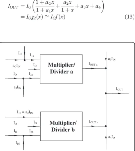
The block diagram of the function synthesizer, based on the original proposed approximation function (1), is pre-sented in Figure 1. The “Multiplier/Divider” circuits are current-mode structures [30,47,48], having the new im-plementation and the description of their operation pre-sented in the following paragraph. The expressions of IOUTaandIOUTbcurrents are
IOUTa¼IOII1a
2a ð10Þ
and
IOUTb¼IOII1b
2b ð11Þ
The output current of the circuit having the block dia-gram presented in Figure 1 will have the following ex-pression:
IOUT ¼IOUTaþIOUTbþa3IINþa4IO ð12Þ
Using the notationx=IIN/IOand relation (1), it results
that IOUT current represents the fourth-order
approxi-mation off(x) function:
IOUT ¼IO 1þaOx 1þa1xþ
a2x
1þxþa3xþa4
¼IOg2ð Þ ffix IOf xð Þ ð13Þ
Multiplier/ Divider a
IOUT a
I2a IO
a1IIN IO
IOUT a3IIN
I2b IO
IIN
IO IOUT b
a4IO IO
I1b = a2IIN IO I1a
aOIIN
Multiplier/ Divider b
The implementation of the“X2”block
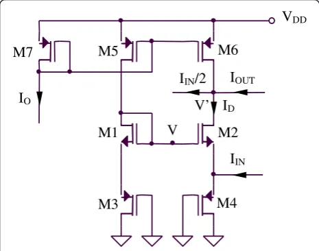
The functional core for designing the “ Multiplier/Div-ider” circuit is represented by a current-mode squaring circuit, having the original implementation presented in Figure 2. The aspect ratios of MOS transistors are 1μ/ 0.54μ for M1–M4 transistors and 0.8μ/0.54μ for M5– M7 transistors.
Noting withVGS(I) the absolute value of the gate–source
voltage of a MOS transistor biased at a drain current equal with I the equation of the translinear loop can be expressed as follows:
2VGSð Þ ¼IO VGSð Þ þID VGSðIDþIINÞ ð14Þ
resulting
2 ffiffiffiffiffiIO p
¼pffiffiffiffiffiIDþ
ffiffiffiffiffiffiffiffiffiffiffiffiffiffiffiffi
IDþIIN p
ð15Þ
Reducing the radicals by squaring the terms and sim-plifying, it results
4IO2IDIIN¼2pffiffiffiffiffiffiffiffiffiffiffiffiffiffiffiffiffiffiffiffiffiffiffiffiIDðIDþIINÞ ð16Þ
equivalent with:
16I2
OþIIN2 16IDIO8IOIIN ¼0 ð17Þ
So
ID¼IOIIN 2 þ
I2
IN
16IO ð18Þ
The expression of the output current will be
IOUT ¼IDþIIN 2 IO¼
I2
IN
16IO ð19Þ
The previous relations can be used only for strong satu-rated devices and for not too small devices. In order to
increase the accuracy of the computations, quasi-identical source–drain voltages for M1–M2 and M3–M4 transistors, respectively, must be imposed. The source–drain voltage of M3 transistor can be expressed as follows
VSD3¼VVGS1ffiVVGS2¼VSD4 ð20Þ
because, considering IIN< <IO, M1 and M2 transistors
are identical and biased at drain currents that differ only with a small amount. Additionally, for biasing M1 and M2 transistors at approximately equal drain– source voltages, V’ potential must be imposed, from the IOUT external terminal, to be equal with V
poten-tial. This particular biasing of M1 and M2 transistors will impose quasi-identical source–drain voltages also for M5 and M6 transistors, this fact increasing the accuracy of M5–M6 current mirror.
The M3–M7 transistors are not affected by the sub-strate effect, as their bulks are connected to their sources terminals. The M1 and M2 transistors have the bulk connected to the ground, so their non-zero bulk-source voltage will be responsible for small errors intro-duced by the substrate effect. As a result, the expression ofIOUTcurrent will slightly be affected by undesired
de-pendencies on technological parameters. The impact of these errors on the overall accuracy of the proposed function synthesizer circuit is small and they can be compensated using specific design techniques. The bias-ing current of the squarbias-ing circuit from Figure 2 is ap-proximately 200μA.
The implementation of the“multiplier/divider”block
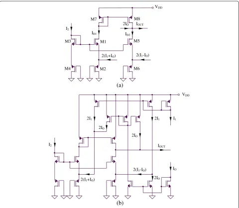
The original proposed“Multiplier/Divider”circuit is pre-sented in Figure 3a, being designed using two current-mode squaring circuits, similar with the structures pre-sented in Figure 2 (M1–M4 and M3–M6, respectively). The full CMOS implementation of the “ Multiplier/Div-ider” circuit is shown in Figure 3b. The complexity of the“Multiplier/Divider”circuit is minimized by re-using M3–M4 transistors for both squaring circuits. The as-pect ratios of MOS transistors are 1μ/0.54μfor M1–M6 transistors and 0.8μ/0.54μ for M7–M8 transistors. The output current has the following expression:
IOUT ¼ID1ID2þ2IO ð21Þ
where two translinear loops similar with the loop ana-lyzed for the “X2” circuit implement the following expressions ofID1andID2currents (derived from (19)):
ID1¼I2ðI1þIOÞ þðI1þIOÞ
2
4I2 ð
22Þ
and
I
DI
INI
OUTI
IN/2
I
OV
DDM3
M4
M2
M1
V
V’
M6
M5
M7
ID2¼I2ðI1IOÞ þðI1IOÞ
2
4I2 ð
23Þ
resulting an output current of the circuit having the fol-lowing expression:
IOUT ¼IOII1
2 ð
24Þ
The original proposed Multiplier/Divider circuit pre-sents two important advantages. First, the current-mode operation increases the frequency response of the compu-tational structure. Second, the independence of the output current expressed by (24) on technological parameters removes, in a first-order analysis, the temperature- and technological-caused errors, the overall accuracy of the proposed circuit being increased in this way. Additionally,
the resulted concrete implementation of the function synthesizer circuit based on the block diagram proposed in Figure 4 has a smaller complexity comparing with pre-viously reported similar computational structures.
Using MOS transistors implemented in 0.18μmCMOS technology, the maximal frequency of operation of the proposed function synthesizer circuit is approximately hundreds kHz - MHz, depending on the particular model of MOS active devices. The biasing current of the “Multiplier/Divider” circuit is approximately 300μA, while the maximal biasing current of the function synthesizer circuit is smaller than 800μA.
Error mechanisms for function synthesizer circuit
Real circuits are affected by a multitude of errors [3,4] that slightly affects their overall accuracy. The most
IOUT
2IO
2(I1-IO)
ID1
I2
VDD
2(I1+IO)
ID2
M2 M1
M6 M4
M5 M3
M8 M7
2(I1-IO)
2(I1+IO)
(a)
IO
2I1 2I1
VDD
I1
I2 IOUT
2IO
2IO
2IO
(b)
important errors that must be taken into account for evaluating the function synthesizer accuracy are pre-sented in the following paragraphs.
The deviation of the MOS transistor characteristic from the square-law, bulk effect, leakage
The saturated MOS transistor squaring characteristic is affected by the second-order effects: mobility degradation (25), channel-length modulation (26), and bulk effect (27):
K¼ KO
1þθGðVGSVTÞ
½ ð1þθDVDSÞ ð25Þ
ID¼K
2ðVGSVTÞ
2 1þλV
DS
ð Þ ð26Þ
VT ¼VTOþγ
ffiffiffiffiffiffiffiffiffiffiffiffiffiffiffiffiffi
ΦVBS
p
pffiffiffiffiΦ
ð27Þ
The errors introduced by the bulk effect [3,4] can be reduced by proper designs that avoid the dependence of the circuit parameters on the threshold voltage. The de-sign of circuits for obtaining a zero bulk-source voltage cancels out the errors introduced by the bulk effect. Additional errors produced by the second-order effects are given by the dependence of K transcon-ductance parameter on VGS voltage. Taking into
ac-count only the K(VGS) dependence, a small changing
of K(VGS) voltage comparing with the analysis based
on the first-order model of MOS transistors can be determined:
VGS¼VTþ ffiffiffiffiffiffiffi
2ID K
r
þθKGID ð28Þ
For latest CMOS VLSI nanometer designs, the leak-age [3,4] becomes more important, the leakleak-age current depending on the properties of the layout and also on the device structure. The determination of the total leak-age cannot be made by adding individual leakleak-age currents, because of a correlation that exists between leakage currents.
The subthreshold leakage is the current produced by minority electrons flowing through p substrate from source to drain, being modeled by an exponential func-tion:
ISL¼IDOWL exp VGSnVVT TH
1 exp VVDS TH
ð29Þ
W/L is the aspect ratio of the MOS transistor,VTH is
the thermal voltage,nis a parameter, andIDOcurrent is
an additional parameter. The subthreshold-off current (obtained for VGS= 0 and VDS> >VT) can be expressed
as follows:
ISLoff ¼IDOWL exp nVVT TH
ð30Þ
The gate leakage current can be carried by tunnel-ing electrons or holes, the carriers leaktunnel-ing to source, drain, and channel. For junction leakage, low cur-rents are carried by minority carriers drifting across the junction, by the electron–hole generation in junction or by the impact ionization at high reverse bias, the electrons being able to pass the barrier by tun-neling through it—Band-To-Band Tunneling current [3,4].
Mismatches in current mirrors
Current mirrors implemented using real circuits present some errors caused by the mismatches between the
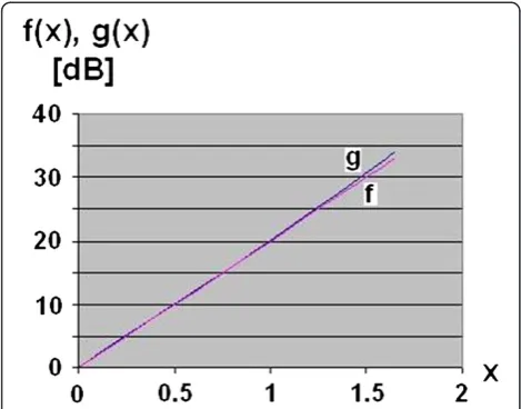
Figure 4Graphical comparison betweeng(x) approximation function andf(x) = exp(x).
Table 1 Comparison betweeng(x) approximation function andf(x) = exp(x)
x g(x) (dB) f(x) (dB) e(dB)
0 0 0 0
0.2 4.075 4 0.075
0.4 8.029 8 0.029
0.6 12.011 12 0.011
0.8 16.028 16 0.028
1.0 20.095 20 0.095
1.2 24.239 24 0.239
1.4 28.495 28 0.495
1.6 32.914 32 0.914
composing MOS transistors and also by the channel-length modulation:
IO IREF ¼
ðW=LÞO
ðW=LÞREF
1þλVDS O
1þλVDS REF ð31Þ
The method for reducing the errors introduced by the channel-length modulation is to impose to the current mirror an output voltage that setVDSOffiVDSREF.
Different threshold voltages and Kn/Kpconstants for NMOS/ PMOS devices
Real circuits present differences between the threshold voltages andKn/Kpconstants for NMOS and PMOS
tran-sistors. In order to avoid additional inaccuracies intro-duced by the practical situation, translinear loops that represent the functional basis of many computational cir-cuits must contain only NMOS or PMOS active devices or must be implemented using quasi-symmetrical struc-tures from the point of view of this complementarily (the same number of NMOS and PMOS transistors).
Variations over the process, temperature, and supply voltage
Most of MOS transistors parameters are affected by the process in which the computational circuits are imple-mented. On the other side, technological parameters present important temperature dependencies. From this perspective, in order to avoid important errors intro-duced by process and temperature, the practical realiza-tions of analog computational circuits must be done in such a way that minimizes the number of technological parameters in the expression of the output signal. Add-itionally, the errors caused by the supply voltage varia-tions can be minimized using self-biased cascode configurations. In this context, a tradeoff between power supply rejection ratio and minimal supply voltage has to be considered.
Applications
An original exponential function generator circuit can be designed using the fourth-order approximation func-tion (1), replacing in general relafunc-tions (3)–(7) the par-ticular values of constant coefficients of expansion (2): m= 1,n= 1, p= 1/2, q= 1/6 and r= 1/24. Theg(x) func-tion that fourth-order approximates the exponential function can be expressed as follows:
g xð Þ ¼16þ21x
165x þ 1 126
1 1þx
7x
11 ð32Þ
Using (8), the approximation error of the exponential function generator will have the following general ex-pression:
Eg xexpð Þð Þxð Þ ffix x5
120 expð Þx ð33Þ
A comparison between g(x) approximation function andf(x) = exp (x) is shown in Table 1.
Figure 5SPICE simulationIOUT(IIN) for the squaring circuit.
A graphical comparison between g(x) approximation function andf(x) = exp (x) is presented in Figure 4.
As a result of using a fourth-order approximation function, the dynamic range of the proposed exponential function generator is approximately 33 dB, for an error smaller than 1 dB.
Simulations
The proposed function synthesizer circuit is designed for implementing in 0.18μm generic CMOS technology, the simulations being based on the square-law SPICE LEVEL 3 model. The parasitic and noise effects have been neglected in the performed analysis, but it could be esti-mated that their impact to the overall accuracy of the pro-posed function synthesizer circuit are relatively small comparing with other causes of errors (approximation error or second-order effects). The overall accuracy of the
proposed fourth-order function synthesizer circuit is 0.3% for an extended range of the input signal.
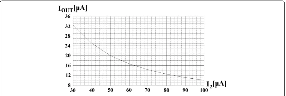
SPICE simulation IOUT(I2) for the Multiplier/Divider
circuit proposed in Figure 3 is presented in Figure 5. The IO and I1 currents have the following values: IO=
50μA and I1= 20μA, while the range of I2 current
was chosen to be between 30μA and 100μA.
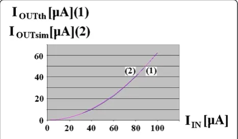
A comparison between the simulated and the theoret-ical estimated results for the proposed current squarer is shown in Figure 6.
SPICE simulation IOUT(I1) for the Multiplier/Divider
circuit proposed in Figure 3 is presented in Figure 7. The IO and I2 currents have the following values: IO=
10μA and I2= 100μA, while the range of I1 current
was chosen to be between 0 and 100μA.
SPICE simulation IOUT(I2) for the Multiplier/Divider
circuit proposed in Figure 3 is presented in Figure 8. The IO and I1 currents have the following values: IO=
Figure 7SPICE simulationIOUT(I1) for the Multiplier/Divider circuit.
50μA and I1= 20μA, while the range of I2 current
was chosen to be between 30μA and 100μA.
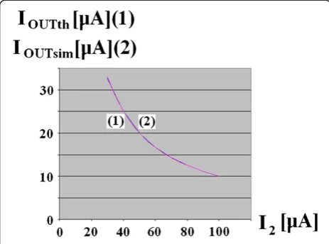
A comparison between the simulated and the theoret-ical estimated results for the proposed current Multi-plier/Divider circuit is shown in Figure 9. The values of IO and I1currents are IO= 50μAand I1= 20μA, while I2
current has values between 30μAand 100μA.
As a result of the particular architecture proposed for the realization of the function synthesizer structure, it presents a low-voltage operation (a minimal supply volt-age of IVfor an implementation in the mentioned tech-nology). This value of the minimal supply voltage was obtained using the theoretical analysis of the proposed function synthesizer circuit (VDDmin= 2VSG+VDSsat) and
also by performing simulations based on the square-law SPICE LEVEL 3 model.
Methods
The necessity of implementing a multitude of continuous mathematical functions in CMOS technology has been solved by the original proposed function synthesizer circuit. A very important advantage of this computational structure is mainly related to its large capability of generating con-tinuous mathematical functions: exponential, multiplying/ dividing, or squaring/square-rooting functions. The original operating method was based on a new fourth-order ap-proximation function, having a superior-order polynomial series that match the polynomial series of the approximated function. The current-mode operation and the independ-ence of the circuit performances on the technological errors are responsible for an additional improvement of structure accuracy. The proposed function synthesizer circuit allows a relatively simple implementation in CMOS technology using only two current-mode Multiplier/Divider circuits.
The designed function synthesizer circuit has the advantages of increased modularity and controllability and of minimal design costs per implemented mathem-atical function. The function synthesizer is designed for implementing in 0.18μm CMOS technology and it is supplied at IV. SPICE simulations confirm the theoret-ical estimated results, showing an accuracy of 0.3% for an extended range of the input signal. This accuracy is exclusively referring to the precision of generating the previous functions, not to the additional circuits that de-serve the proposed function synthesizer structure.
The speed of the original proposed function generator circuit is correlated with its overall accuracy, expecting the necessity of making a tradeoff between the previous per-formance parameters. Additionally, especially for extreme small values of the approximation error, the noise of the cir-cuit can slightly degrade the circir-cuit performances.
As an immediate application of the function synthesizer circuit, it was proposed a new exponential function gener-ator based on a particular fourth-order approximation function. The circuit has a dynamic range of approxi-mately 33 dB, in the conditions of limiting the error to 1 dB.
Abbreviations
CMOS: complementary metal oxide semiconductor; MOS: metal oxide semiconductor; VLSI: very large-scale integration.
Competing interests
The author declares that they have no competing interests.
Acknowledgments
The author thanks Professor Maurits Ortmanns from Institute of
Microelectronics, University of Ulm for reviewing the article and for helpful discussions, the collaboration with him bringing many improvements to the article.
Author’s information
Cosmin Radu Popawas born in Constanta, Romania. He received the B. Eng. degree in electronic engineering and telecommunications in 1997, the M.Sc. degree in microelectronics in 1998, and the Ph.D. degree in electronic engineering and telecommunications with Summa Cum Laude distinction in 2004 from the University Politehnica of Bucharest, Romania. Currently, he is a lecturer at Faculty of Electronics,
Telecommunications and Information Technology, Bucharest, Romania. In 2006, he earned“In Hoc Signo Vinces”award, Magna Cum Laude distinction from The National Council of Scientific Research and, in 2008,
“In Tempore Opportuno”award from University Politehnica of Bucharest, both from excellence in research activity. From 2010, he is involved in a Postdoctoral Research Fellow with the same faculty. His main area of research is analog and mixed signal integrated circuits for low-power low-voltage applications and analog signal processing. Dr. Popa is author of five books (two of them published with Springer) covering the domains of analog signal processing circuits and, also, of more than 150 papers published in the most important international journals and conference proceedings.
Received: 20 February 2012 Accepted: 23 June 2012 Published: 13 July 2012
References
1. G Rittenhouse, S Goyal, DT Neilson, S Samuel,Sustainable
telecommunications(Technical Symposium at ITU Telecom World, Geneva, Switzerland, 2011), pp. 19–23
2. F Altiparmak, B Dengiz, AAE Smith, General neural network model for estimating telecommunications network reliability. IEEE Trans. Reliab.58(1), 2–9 (2009)
3. C Popa,Superior-Order Curvature-Correction Techniques for Voltage References
(Springer, New York, 2009)
4. C Popa,Synthesis of Computational Structures for Analog Signal Processing
(Springer, New York, 2011)
5. CC Du Preez, S Sinha, M du Plessis, CMOS ECG, EEG and EMG waveform bio-simulator. International Semiconductor Conference1, 27–29 (2006). September 2006, Sinaia, Romania, pp. 29–38
6. F Pini, K McCarthy,Capacitive instrumentation amplifier for low-power bio potential signal detection(Paper presented at Signals and Systems Conference, Cork, Ireland, 2010), pp. 54–58. 23–24 June 2010 7. C Azzolini, A Ricciardi, A Boi,Very low-cost CMOS audio amplifier for 1-V
portable applications(Paper presented at 3rd International Conference on Design and Technology of Integrated Systems in Nanoscale Era, Tozeur, Tunisia, 2008), pp. 25–27. pp. 1–4
8. C Azzolini, A Boni, A 1-V CMOS audio amplifier for low cost hearing aids, in Paper presented at 15th IEEE International Conference on Electronics, Circuits and Systems, 31 August–3,St(Julian's, Malta, September 2008), pp. 562–565 9. DC Wei, DQ Sun, AA Abidi, A 300-MHz fixed-delay tree search-DFE analog
CMOS disk-drive read channel. IEEE J. Solid State Circuits36(11), 1795–1807 (2001)
10. T Ndjountche, L Fa-Long, C Bobda,A CMOS front-end architecture for hard-disk drive read-channel equalizer(Paper presented at IEEE International Symposium on Circuits and Systems, Kobe, Japan, 2005), pp. 2184–2187. vol. 3, 23–26 May
11. C Hwang-Cherng, W Jia-Yu,High CMRR instrumentation amplifier for biomedical applications(Paper presented at 9th International Symposium on Signal Processing and Its Applications, 12–15 February 2007, Sharjah, United Arab Emirates, 2007), pp. 1–4
12. MR Haider, SK Islam, S Mostafa, Z Mo, O Taeho, Low-power low-voltage current readout circuit for inductively powered implant system. IEEE Trans. Biomed. Circuits Syst.4(4), 205–213 (2010)
13. R Dlugosz, T Talaska, W Pedrycz, R Wojtyna, Realization of the conscience mechanism in CMOS implementation of winner-takes-all self-organizing neural networks. IEEE Trans. Neural Netw.21(6), 961–971 (2010)
14. IE Ebong, P Mazumder, CMOS and memristor-based neural network design for position detection. Proc. IEEE99, 1–11 (2011)
15. K Ming-Dou,ESD-aware circuit design in CMOS integrated circuits to meet system-level ESD specification in microelectronic systems(Paper presented at International Conference of Electron Devices and Solid-State Circuits, Tianjin, China, 2011), pp. 1–2. 17–18 November 2011
16. L Seung-Chul, J Young-Deuk, K Jong-Kee, K Jongdae, A 10-bit 205-MS/s 1.0-mm290-nm CMOS pipeline ADC for flat panel display applications. IEEE J. Solid State Circuits42(12), 2688–2695 (2007)
17. N Sudha, K Sridharan, A high-speed VLSI design and ASIC implementation for constructing Euclidean distance-based discrete Voronoi diagram. IEEE Trans. Robot. Autom.20(2), 352–358 (2004)
18. T Villmann, FM Schleif, B Hammer,Fuzzy Labeled Soft Nearest Neighbor Classification with Relevance Learning(Paper presented at Fourth International Conference on Machine Learning and Applications, Los Angeles, USA, 2005), pp. 11–15. 15–17 December 2005
19. I Triguero, J Derrac, S Garcia, F Herrera, A taxonomy and experimental study on prototype generation for nearest neighbor classification. IEEE Trans. Syst. Man Cybern. C: Appl. Rev.42(1), 86–100 (2012)
20. A Rodríguez-Vázquez, R Domínguez-Castro, F Jiménez-Garrido, S Morillas, A García-Ortiz, C Utrera, MD Pardo, J Listan, R Romay, inCellular Nanoscale Sensory Wave Computing—A CMOS Vision System On-Chip with Multi-Core, Cellular Sensory-Processing Front-End, ed. by C. Baatar, W. Porod, T. Roska (Springer, New York, 2010), pp. 129–146
21. C Sawigun, J Mahattanakul,A 1.5 V, wide-input range, high-bandwidth, CMOS four-quadrant analog multiplier(IEEE International Symposium on Circuits and Systems, Washington, USA, 2008), pp. 2318–2321. 18–21 May 2008 22. BC Akshatha, VK Akshintala,Low voltage, low power, high linearity, high speed
CMOS voltage mode analog multiplier(Paper presented at 2nd International Conference on Emerging Trends in Engineering and Technology, Nagpur, India, 2009), pp. 149–154. 16–18 December 2009
23. SA Mahmoud,Low voltage low power wide range fully differential CMOS four-quadrant analog multiplier(Paper presented at 52nd IEEE International
Midwest Symposium on Circuits and Systems, Cancun, Mexico, 2009), pp. 130–133. 2–5 August 2009
24. A Naderi, A Khoei, K Hadidi,High speed, low power four-quadrant CMOS current-mode multiplier(Paper presented at 14th IEEE International Conference on Electronics, Circuits and Systems, Marrakech, Morocco, 2007), p. 1311. 11–14 December 2007
25. M Gravati, M Valle, G Ferri, N Guerrini, N Reyes,A novel current-mode very low power analog CMOS four quadrant multiplier(Paper presented at 31st European Solid-State Circuits Conference, Grenoble, France, 2005), pp. 495– 498. 12–16 September 2005
26. C Sawigun, WA Serdijn, Ultra-low-power, class-AB. CMOS four-quadrant current multiplier. Electron. Lett.45(10), 483–484 (2009)
27. R Hidayat, K Dejhan, P Moungnoul, Y Miyanaga,OTA-based high frequency CMOS multiplier and squaring circuit(Paper presented at International Symposium on Intelligent Signal Processing and Communications Systems, Bangkok, Thailand, 2009), pp. 1–4. 8–10 Ferbruary 2009
28. W Machowski, S Kuta, J Jasielski, W Kolodziejski,Quarter-square analog four-quadrant multiplier based on CMOS invertes and using low voltage high speed control circuits(Paper presented at 17th International Conference Mixed Design of Integrated Circuits and Systems, Wroclaw, Poland, 2010), pp. 333– 336. 24–26 June 2010
29. M Ehsanpour, P Moallem, A Vafaei,Design of a novel reversible multiplier circuit using modified full adde(Paper presented at International Conference on Computer Design and Applications, Qinhuangdao, China, 2010), pp. V3-230–V3-234. vol. 3, 25–27 June 2010
30. A Naderi, H Mojarrad, H Ghasemzadeh, A Khoei, K Hadidi,Four-quadrant CMOS analog multiplier based on new current squarer circuit with high-speed
(IEEE International Conference on“Computer As A Tool, Saint Petersburg, Russia, 2009), pp. 282–287. 18–23 May 2009
31. C.H. Kao, C.C. Tseng, C.S. Hsieh, Low-voltage exponential function converter. IEE Proc. Circuits Dev. Syst.152(5), 485–487 (2005)
32. S Ethier, M Sawan, Exponential Current pulse generation for efficient very high-impedance multisite stimulation. IEEE Trans. Biomed. Circuits Syst99, 1–9 (2010)
33. H Hedayati, B Bakkaloglu,A 3 GHz widebandPΔfractional-N synthesizer with voltage-mode exponential CP-PFD(Paper presented at IEEE Radio Frequency Integrated Circuits Symposium, Boston, USA, 2009), pp. 325–328. 7–9 June 2009
34. D Moro-Frias, MT Sanz-Pascual, CA de la Cruz-Bias,Linear-in-dB Variable Gain Amplifier with PWL exponential gain control(Paper presented at IEEE International Symposium on Circuits and Systems, Paris, France, 2010), pp. 2824–2827. 2010
35. CA De La Cruz Blas, O Feely, Limit cycle behavior in a class-AB second-order square root domain filter, in Paper presented at 15th IEEE International Conference on Electronics, Circuits and Systems, 31 August–3,St(Julian's, Malta, September 2008), pp. 117–120
36. B Boonchu, W Surakampontom,A CMOS current-mode squarer/rectifier circuit
(Paper presented at International Symposium on Circuits and Systems, Bangkok, Thailand, 2003), pp. I-405–I-408. vol. 1, 25–28 May 2003 37. CA De La Blas, A Lopez, A novel two quadrant MOS translinear
Squarer-divider cell, in Paper presented at 15th IEEE International Conference on Electronics, Circuits and Systems, 31 August–3 Sptember,St(Julian's, Malta, 2008), pp. 5–8
38. CA De La Cruz-Blas, AJ Lopez-Martin, A Carlosena, 1.5-V square-root domain second-order filter with on-chip tuning. IEEE Trans. Circuits Syst. I: Regular Papers52(10), 1996–2006 (2005)
39. G Raikos, S Vlassis,Low-voltage CMOS voltage squarer(Paper presented at 16th IEEE International Conference on Electronics, Circuits, and Systems, Yasmine Hammamet, Tunisia, 2009), pp. 159–162. 13–16 December 2009 40. V Garofalo, M Coppola, D De Caro, E Napoli, N Petra, AGM Strollo,A novel
truncated squarer with linear compensation function(Paper presented at IEEE International Symposium on Circuits and Systems, Paris, France, 2010), pp. 4157–4160. 30 May–2 June 2010
41. A Kircay, MS Keserlioglu,Novel current-mode second-order square-root-domain highpass and allpass filter(Paper presented at International Conference on Electrical and Electronics Engineering, Bursa, Turkey, 2009), pp. 242–246. 5–8 November 2009
42. C Popa,A New FGMOST Euclidean Distance Computational Circuits Based on Algebraic Mean of the Input Potentials(Springer, Berlin, 2009), pp. 459–466.
43. A Hyo-Jin, C Chang-Seok, L Hanho,High-speed low-complexity Folded Degree-Computationless Modified Euclidean algorithm architecture for RS decoders(Paper presented at 12th International Symposium on Integrated Circuits, Singapore, Singapore, 2009), pp. 582–585. 14–16 December 2009 44. MT Abuelma’atti, NM Al-Yahia,An improved universal CMOS current-mode
analog function synthesizer(Paper presented at International Symposium on Integrated Circuits, Singapore, 2007), pp. 580–583. 26–30 September 2007 45. MT Abuelma’atti, Universal CMOS current-mode analog function synthesizer.
IEEE Trans. Circuits Syst. I: Fund. Theory Appl49(10), 1468–1474 (2002) 46. MT Abuelma’atti,A translinear current-mode programmable analog
exponential function synthesizer(Paper presented at Eleventh International Conference on Microelectronics, Kuwait, 1999), pp. 209–212. 22–24 November 1999
47. C Psychalinos, S Vlassis, A systematic design procedure for square-root-domain circuits based on the signal flow graph approach. IEEE Trans. Circuits Syst. I: Fund. Theory Appl.49(12), 1702–1712 (2002)
48. GA Baker, P Graves-Morris,Padé Approximants (Cambridge University Press
(Cambridge, MA, 1996)
doi:10.1186/1687-6180-2012-146
Cite this article as:Popa:High-accuracy function synthesizer circuit with applications in signal processing.EURASIP Journal on Advances in Signal Processing20122012:146.
Submit your manuscript to a
journal and benefi t from:
7 Convenient online submission
7 Rigorous peer review
7 Immediate publication on acceptance
7 Open access: articles freely available online
7 High visibility within the fi eld
7 Retaining the copyright to your article