Systems Reference Library
Operator's Guide for IBM 7040 -7044 Systems
This publication is intended for personnel operating
IBM 7040 and 7044 systems. It describes lights,
switches, indicators, and keys of the systems, and of units within the systems. Instructions and operation code lists are included. The reader should be familiar with IBM 7040-7044 Principles of Operation, Form A22-6649.
This edition, Form A22-6741-1, obsoletes the preceding edition, Form A22-6741.
Copies of this and other IBM publications can be obtained through IBM Branch Offices. Address comments concerning the content of this publication to:
Introduction
Instructions and Data . Machine Cycles Operator's Console
Processing Unit Data Flow Input-Output Devices
Magnetic Tape Units
IBM 7330 Magnetic Tape Unit Keys and Lights
Card Devices. . . . .
IBM 1402 Card Read Punch, Model 2 IBM 1402 Card Read Punch, Model 2 Printer
IBM 1403 Printer, Models 1 and 2 Telecommunication Devices . IBM 1009 Data Transmission Unit . IBM 1011 Paper Tape Reader . IBM 1014 Remote Inquiry Unit Operations . . . . Loading Card Data - 1402 . Loading Magnetic Tape Data Loading Entry Key Data . Off-Line Operation
Appendix A. Instructions
Appendix B. Instruction List
Appendix C. Powers of Two Table Appendix D. Octal-Decimal
Contents
5 5 7 8 12 12
13 . 16
18 19 19
22 22
37 37 41 49
51 51 52 53 54
56 59
64
Integer Conversion Table. . . . 65 Appendix E. Octal-Decimal
The operator's console contains a program con-trolled console typewriter, keys, switches, and lights for communication between operator and computer (Fig-ure 1). Two banks of entry keys and an enter keys computer instruction make possible the entry of a full data word or instruction into the computer. This entry may be either manual or program controlled.
Information is set into the keys in octal format. The contents of main processing unit registers and counters are displayed in lights on the console. Certain control and error indications also are displayed on the console for viewing and action.
The processing unit controls and supervises the entire computer system and performs the actual arith-metic and logical operations on data. From a functional viewpoint, the processing unit consists of two sections: control and arithmetic-logical.
The control section can start or stop an input-output device, tum a signal indicator on or off, rewind a tape reel, or direct some process of calculation.
The arithmetic-logical section contains the circuitry to perform arithmetic and logical operations. The arithmetic portion calculates, shifts numbers, sets the algebraic sign of results, compares, and so on. The logical portion carries out the decision-making oper-ations to change the sequence of instruction execution.
Instructions and Data
Instructions are distinguished from data by the time at jhich they are brought into the processing unit from core storage. Information that is brought into the processing unit during an instruction (I) cycle is interpreted as an instruction. Information that is
Figure 2. Register Nomenclature and Function
Introduction
brought into the processing unit during any other computer cycle is treated as data. Consequently, the computer can readily operate on' its own instructions, by bringing information into the processing unit during any cycle other than an I cycle. Also, the computer can be instructed to alter its own instructions according to conditions encountered during the handling of a pro-cedure.
It is this ability to process instructions that provides the almost unlimited flexibility and the so-called logi-cal ability of the stored program computer system. Register
The register is an electronic device capable of re-ceiving and holding information, and transferring it as directed by control circuits. Functioning may depend upon magnetic cores, transistors, or similar compo-nents.
Registers are . named according to function: an accumulator register accumulates results; a multiplier-quotient register holds either multiplier or multiplier-quotient; a storage register contains information received from storage or to be sent to storage; an address register holds the address of a storage location or device; and an instruction register contains the instruction code (operation part) of an instruction being executed (Figure 2).
Registers differ in size, capacity, and use. Some regis-ters contain extra positions to indicate overflow condi-tions during an arithmetic operation. The accumulator register has 39 positions; 36 for data, two (P and Q) to remember overflow conditions, and one (C) which holds a check bit for that word. If two 36-bitbinary numbers are added, the result can be a 37 -bit an-swer. In Figure 3, the accumulator register holds one number; the other number - from storage - is in the storage register. When the two numbers are added, and the result is placed back into the accumulator register, the overflew is indicated by the presence of a I-bit in the first (P) overflow position. The
ac-Accumulator Contents
Storage Register Contents
Accumulator Result
1000,100110111010001101010011100010101011
SQP.l 35
lo~ 10110001010001101101100010100100101
~1 u
1001~)l1101000100011010111111110111001111
SQP. 1 35
Figure 3. Overflow Condition Resulting from Addition
cumulator might then be shifted right one place and a record kept of the lost low-order hit.
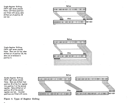
With other registers, contents can be shifted right or left within the register and, in some cases, even be-tween registers. When contents are shifted from one register to another, the two registers act as one large register. Figure 4 shows three types of shifting. With shifting involving a single register, data shifted out of the register mayor may not be lost, depending on the instruction used. With double register shifting, data shifted out of the registers are lost, and vacated posi-tions of the registers are filled with zeros.
In other uses, a register may hold data while associ-ated circuits analyze the data. When an instruction is placed in a register, circuits can determine the oper-ation to be performed and locate the data to he used. Data within specific registers can also be checked for validity.
The main registers of a system, particularly those involved in normal data How and core storage address-ing, display their contents by small lights located on
Single Register Shifting: (Shift right seven places) Note: Left-hand positions are filled with zeros; data shifted out of position 35 are lost.
Single Register Shifting: (Shift right seven places) Note: Data are not lost when shifted out of position 35; the data are re-entered in position S.
Double Register Shifting: (Shift right seven places) Note: Data are shifted from position 35 of the first register into position S of the second register. DatQ shifted out of position 35 of the second register are lost. Vacated positions are filled with zeros.
Figure 4. Types of Register Shifting
6
the operator's console. A light ON indicates a I-bit for
that position: a light OFF indicates a O.:hit.
Counter
Counters are closely related to registers and usually perform the same functions. In addition, contents of a counter can be increased or decreased by some amount. The contents of a counter, as of a register, may be displayed in lights on the operator's console.
Adder
The adder receives data from two or more sources, performs addition, and sends the sum to a register. Figure 5 shows two positions of an adder circuit with inputs from an accumulator register and a storage register. The sum is developed in the adder. A carry from any position is sent to the next higher-order posi-tion. The final sum goes to corresponding positions of the receiving register.
Before
[image:6.617.28.544.333.746.2]Figure 5. Adders in a Computer System
Machine Cycles
All computer operations take place in fixed intervals of time, determined by regular pulses emitted from an electronic clock at frequencies as high as millions per second. A fixed quantity of pulses determines the time of each basic machine cycle.
Within a machine cycle, the computer performs a specific machine operation. The quantity and kind of operations required to execute a single instruction depend on the instruction. Various machine operations are combined to execute each instruction.
An instruction consists of at least two parts, an oper-ation and an operand. The operoper-ation tells the machine which fmiction ·to perform: read, write, add, subtract, and so on. The operand can be the address of data or of an instruction, or of an input-output unit or other device. The operand can also specify a control function such as shifting a quantity in a register, or backspacing and rewinding a reel of tape.
To receive, interpret, and execute instructions, the central processing unit must operate in a prescribed sequence. The sequence is determined by the specific instruction and is carried out during a fixed interval of timed pulses.
All instructions have one instruction (I) cycle. Some instructions require only an I cycle for complete execu-tion; other instructions require both an I and an exe-cute (E) cycle.
Instruction Cycle
The first cycle required to execute an instruction is called the instruction (I) cycle. The time of this cycle is instruction or I-time. During I-time:
1. The instruction is taken from a main storage loca-tion and brought to the processing unit.
2. The operation part is decoded in an instruction register. This tells the machine what is to be done. 3. The operand is placed in an address register. This tells the machine what it is to work with.
4. The location of the next instruction to be exe-cuted is determined.
At the beginning of a program, the instruction coun-ter is set to the address of the first program instruction.
This instruction is brought from storage and, while it is being executed, the instruction counter automatically advances (steps) to the address of the location occu-pied by the next stored instruction. By the time one instruction is executed, the counter has located the next instruction in the program sequence. The stepping action of the counter is automatic: when the computer is directed to a series of instructions, it will execute these instructions one after another until instructed to do otherwise.
Assume that an instruction is given to add the con-tents of storage location 00002 to the concon-tents of the accumulator register. Figure 6 shows the main registers involved and the information flow lines.
At the start of I-time, the instruction counter trans-fers the address of the instruction to the address regis-ter. The addressed instruction is selected from storage and placed in a storage register. From the storage register, the operation part is routed to the instruc-tion register, and the operand to the address register. Operation decoders then condition circuit paths to per-form the instruction, while the address register locates the operand.
Execution of instructions need not necessarily pro-ceed sequentially. Certain instructions can alter the normal stepping of the instruction counter: the instruc-tion brought from storage can cause the next execuinstruc-tion to be not the next sequential instruction, but, instead, one located in another position. For instance, the instruction counter can be reset back to the beginning to repeat the entire program for another incoming group of data.
This transfer ( branch) to alternative instructions also may be conditional. The computer can be directed first to examine some indicating device, and then trans-fer if the indicator is on, or off. An instruction can say, "Look at the sign of the quantity in the accumulator; if this sign is minus, take the next instruction from location 5000; if plus, proceed to the next instruction in sequence." The instruction counter is set according to the contents of one of two possible storage loca-tions: 5000, or the location of the next instruction in sequence. The logical path - that is, the precise
Figure 6. Computer I Cycle Flow Lines
sequence of instructions executed - may be con-trolled either by unconditional transfers, or by a series of conditional tests applied at various points in the pro:-gram. Normally the storage arrangement of the stored instructions is not altered.
Execute Cycle
I-time is usually followed by one or more computer cycles which complete the operation being perfonned. Execution of an E cycle brings a word into the process-ing unit from core storage, or takes a word from the processing unit and places it in core storage. Any word brought into the processing unit during an E cycle is treated as data for the operation decoded by the pre-vious I cycle. Figure 7 shows the data flow following the I-time illustrated by Figure 6.
The E-cycle (Figure 7) starts by removing from stor-age the infonnation located at the address (00002) in-dicated by the address register. The infonnation goes to the storage register, from which it is then moved to the adders together with the number from the lator. The contents of the storage register and accumu-lator are combined in the adders, and the sum is returned to the accumulator.
The address register may contain information other than the storage location of data. It can indicate the address of an input-output device, or a control func-tion to be perfonned. The operafunc-tion part of the instruction tells the computer how to interpret this information.
Buffer Cycle
Buffer cycles are used to transfer information between an overlap data channel (channels B through E) and an input-output device.
Use Cycle
Use cycles are used to transfer infonnation between channel A and attached input-output devices.
number at location 00002
t the number located at 00002
Address Register
Instruction Counter
Figure 7. Computer E Cycle Following an I Cycle
Operator's
Console
The operator's console has five panels (Figure 8) containing keys, lights, and switches that provide flexi-ble, efficient communication between the computer and the operator. The following descriptions of console features start· at the top left-hand comer of panel 1 and continue through panel 5.
Panel 1
Channel Bit Density: Five density switches are used, one for each possible data channel, to select the mag-netic tape densities used for recording. Each switch has three positions: 556/200, 800/200, and 800/556. Thus, a magnetic tape unit whose channel bit density switch is in the 800/556 position would record at800 bits per inch if operating at high density, at 556 bits per inch if operating at low density.
Storage Clock: With this switch in the ON position, core storage location 00005 is incremented (added to) 60 times a second. Incrementing is stopped by placing the switch in the OFF position or by removing power
from the system.
Step Mode Selector: This three position rotary switch controls the operation mode when the single or multiple step keys are depressed. The three positions of the selector switch are: INSTRUCTION, CYCLE, PULSE. INSTRUCTION is the normal operation position and pro-vides for execution of a single instruction at a time when the single step key is used. The CYCLE and PULSE
positions are customer engineering aids and allow ex-ecution to be slowed to observe details of a single instruction.
Address Stop:. This five-position switch is used in conjunction with the entry (location) switches and has these positions: OFF, I-Cycle, E-Store, Channel Store, and Any. The address at which the operator wishes to stop is first placed in the entry (location) switches. The operator then selects the type of cycle on which to stop. When a coincidence of the selected address and the cycle occurs, the computer stops.
Panel 2
C B Thermal: This light is turned ON whenever a
circuit breaker, fuse, thermal, or airflow switch in the basic system or auxiliary equipment opens. Power is removed from the system if the opening switch is in the central processing unit (cPu). In auxiliary equip-ment, power is removed only from the unit.
~
Channel Bit Density
~ .!!QQ ll.QQ. ~
200 200 200 200 200
556 ••• I.!QQ ~ ••• !!QQ 556 ••• !!QQ ~ ••• §Q,Q 556 ••• 800 200 @ 556 200 ® 556 200 © 556 200 ® 556 200 ® 556
Storaie Clock .r"'--S M d I _ . Off
0
On Inst·OPulse tep 0 e Cyc e :0-.
Index A
121 22 23
I
24 25 26 1 27 28 29I
30 31 3213334 351CB
J
Thermal Light IMaster powerj Connect IMas~er powerj DlSconn I Norm~nPowe1 I Normal powerj Off
DDDDDDDDDDDDDDD
Channel in Use I Channel Chk I Position Reg I Index BA B C o E
J
A 8 C 0 ElF 14 15 16 171 121 22 23 1 24 25 26 I 27 28 29 I 30 31 32 I 33 34 351DDDDDDDDDDDDDDD
Instruction CounterDDDDDDDDDDDDDDD
Index C121 22 23 1 24 25 26 1 27 28 29 1 30 31 3213334351 121 22 23 1 24 25 26 1 27 28 29 1 30 31 32 1 33 34 35 1
DDDDDDDDDDDDDDD
DDDDDDDDDDDDDDD
Instruction Sh ift Counter I Tag I Address
IT] 1 2 3 I 4 5 6 I 7 8 9 110 11 112 13 14 115 16 17 I 18 19 20 I 21 22 23 I 24 25 26 I 27 28 29 I 30 31 321333435
D DDDDDDDDDODDDDDDDDDDODDODDDDDDDDDDO
Storage[U 11 2
I
3 4 5I
6 7 81 9 10 11 112 13 14 115 16 17118 19 20121 22 23124.25 26127 28 291 30 31 32 133 34 35 1 ~0 DDDDODDDDDDDDDDDDDDDDDDDDDDDDDDDDDD
Accumulator0
DDODO'ODO'ODo'oodODO'O
00100010001000100010001000
MQ
IT] 11 2
I
3 4 5I
6 7 8I
9 10 11 112 13 14 115 16 17118 19 20 121 22 23 124 25 261 27 28 29130 31 32I
33 34 351 [JD DDDDDDDDDDDDDDDDDDDDDDDDDDDDDDDDDDD D
Cycl~ Time Mas Prog Par Tally Counter I E L B a f3 Stop Stop Ready
8 B
I~~::Ie
I I~:~~~:~
jBJ
DDDO[ ODD
OJ
D
DODO
0 DC
I'~~:;::k
1
Clock Pulses Accu Div 10 Par Trp Trp Mem Q Ch X 9 9 FP FP~~'
10
DDDO[
nOD
Inh Inh Ctl Prot Car Car Car Oflo 1 2
B
I
MultipleI
Enter\I
DOD D
DOD 0 0
rn
I
Contn;tnter
I
Step StorageI
ClearI
Sense Location
CD
0
0
0
CD
Emergency (0 (0
0
0
0
Q
Power
0)
CD
0
0
0
0)Off
m
CD
0
0
0
0
0
CD
CD
0
0
0
G)CD
CV
0
0
0
CD
CD
CD
0
0
0
CD
CD
0
0
0
C0
Instruction Tag Address
@
0
0
0
0
0
0
0
0
0
0
CD
@
CD
0
0
0
0
0
0
0
0
0
@)Q
<0
0
0
0
0
G)0
0
0
0
<0
@
0
0
0
0
0
Q0
0
0
0
CD
@ G)
0
0
0
0
G)0
0
0
0
G)@
CV
0
0
0
0
G)0
0
0
0
V
@
<D
0
0
0
0
CD
0
0
0
0
CD
(!9) CQ)
0
0
0
0
(Q)0
0
0
0
CQ)Figure 8. Operator's Console Panel
Master Power Disconnect: This switch controls power circuits and power applied to the sequencing controls. All power components under control of the system are disconnected from the line power. The power-on switch has no effect in this condition. Press-ing this switch (with the system operatPress-ing) results in a sequenced power-off operation.
Normal Power On: Pressing this switch starts a power-on sequence for the CPU and auxiliary
equip-ment under control of the power distribution unit. Normal Power Of]: Depressing the power-off switch removes all DC voltages and air blower circuits in
se-quence. The -48 volts control voltage and convenience outlet power remain on.
Channel in Use (A through E): The channel in use indicators, one for each channel, are on for each data channel that is in operation.
Channel Check (A through E): The channel check indicators, one for each channel, are on when a byte or word redundancy has been detected.
Position Register: These five lights reflect the con-tents of the indirect address trigger (F) and positions 14-17 of the instruction being executed. Positions 15-17 indicate which adapter is being used on a select in-struction and the character selected on character-han-dling instructions.
Instruction Counter: These lights reflect the contents of the instruction counter.
Index A, B, and C: These lights, one for each posi-tion of each index register, reflect the contents of the index registers.
Panel 3
. Internal CPU Registers: The contents of the in-struction register, shift counter, tag register, address counter, storage register, accumulator register, and multiplier-quotient register are reflected by these lights.
Storage Register C: This light reflects the contents of the 37th. bit of the word in the storage register. MQ Register C: This light reflects the parity bit contents of the word being used in an input-output operation on data channel A.
Panel 4
Reset: Pressing this key resets all registers and in-dicators in the logic section of the processing unit. Core storage is not affected by the reset key, but all data channel registers and indicators are reset.
Automatic: This switch is lit when in AUTOMATIC
position. Placing this switch in the MANUAL position
stops the processing unit after it has completed execu-tion of the instrucexecu-tion being processed, unless an input-output device is in use. In this case, the
com-puter continues execution of instructions and remains in automatic status until all input-output devices have been disconnected. When the processing unit stops (with this switch in manual) the computer is in manual status. The storage clock continues to run.
Single Step/Multiple Step: When the CPU is in
manual status, these keys enable the operator to pro-ceed with his program either one step at a time or at a slow automatic speed. If the computer executes an instruction that causes an input-output unit to be selected, the computer operates :in automatic mode until the input-output unit is disconnected. When the disconnect occurs, the computer returns to manual status.
Display Storage: With the CPU in manual status,
pressing the display storage key displays the contents of the core storage location addressed by the entry keys of panel 5. The contents are displayed by the lights associated with the storage register. If the stor-age clock optional feature is installed, the storstor-age clock switch must be turned off to maintain the displayed word in the storage register.
Load: This key is active in automatic when the CPU
is stopped and no channels are in operation. It is also operative as a program reset any time the automatic key is on. The following occurs when the load key is depressed.
When the automatic key is not on (manual mode): 1. If an instruction is in process it is given a brief
period of time to complete.
2. At the end of this time, an interlock reset occurs even if the present instruction has not completed. The interlock and all other possible resets are described at the end of this section .
When the autom~tic key is on (automatic mode): 1. The instruction set up in the entry keys is
exe-cuted.
2. The instruction set up in the keys should select a channel and put the channel in use. A channel command with maximum word count and an address of 00100 is loaded into the selected chan-nel. Whep. the channel in use indicator is turned off, the computer transfers control to location 00101 and continues instruction execution from there.
Start: Pressing the start key continues operation at high speed if the computer has stopped at a program stop, or if the CPU has been returned to automatic
after having been in manual status. The start key re-sets the program stop light, and operations start at the address specified by the contents of the instruction counter.
Enter Storage: With the CPU in manual status,
Enter Instruction: Pressing this key executes the in-struction set up in the word bank of the entry keys .. The CPU must be in manual status.
Cycle Timer (I, E, L, B,a, f3): The cycle timer lights reflect the current machine cycle being executed. Status of the alpha and beta triggers are also reflected for a 7106 CPU.
Master Stop: This light is on whenever the master stop trigger is on (cPu is logically stopped).
Program Stop: This light is on whenever the com-puter executes a halt instruction.
Ready: This light is ON after power is applied to the
computer and remains on except when the computer is in automatic status and the continuous enter-instruc-tion switch is on or the 1-0 interlock switch is in
MANUAL.
Clock Pulses (AD through A5): These lights reflect the state of the timing ring.
Accumulator Overflow: This light is on during any fixed-point or shifting operation that gives a carry out of position 1 of the accumulator. The light is turned off by execution of a TOV instruction or depression of the
reset key.
Divide Check: This light is turned on in fixed-point division if the dividend (accumulator contents) is greater than or equal to the divisor (storage register contents). In floating-point operation, the light is on if the magnitude of the fraction of the divid&nd is greater than or equal to twice the magnitude of the' divisor fraction. The light is tested and turned off by execution of the DCT instruction.
I -0 Check: The 1-0 check light may be turned on by
any of the following conditions:
1. If an RCR instruction is decoded and the specified
data channel has not been selected.
2. If, during writing, a channel data register has not been loaded with a word from storage by the time its contents are to be sent to the output unit. S. If, during reading, a channel data register has not transmitted its contents to storage by the time that new data are to be loaded into it from an input unit. This is not true during a tape opera-tion when an RCR (following an RDs) is given
too late.
The I-a check light may be turned off by execution
of an lOT instruction.
Parity Check: This light is turned on when the parity circuits detect an error. It will be on when the
CPU stops on error during storage test operations.
Tally Counter (1, 2, 3, 4, 5, 6, 10, 20, 30): The tally counter differentiates between the L cycles of a float-ing-point instruction and provides gating for their different operational steps. The counter is divided into two stages. Lights on the console' reflect which stage the CPU is currently operating in. Positions 1 through 6
indicate the flow of single precision floating point and positions 10, 20, and SO together with positions 1 through 6 indicate the flow of double precision float-ing point.
1-0 Interlock Control: When the light in this switch is on, the switch is in MANUAL position; when the light
is off the switch is in automatic position. The switch is used with the auto-manual switch as an aid in locating
I-a problems. The switch functions as follows:
1. If an I-a unit is selected with the I-a interlock light off, system operation reverts to automatic status even though the auto-manual switch is in
MANUAL.
2. If the I-a interlock light is on and the CPU is in
manual status when an '1-0 unit is selected, the
CPU executes the select and remains in manual
status.
Parity Inhibit: This light is on whenever parity traps are inhibited as a result of a previous parity trap. The light is turned off by execution of a TRP instruction or a
machine reset.
Trap Inhibit: This light is on when all interrupt traps are inhibited as a result of a parity or interval timer reset trap. The light is turned off with execu-tion of the TRT or TRP instructions or a machine reset.
Channel Trap Control: This light is off when chan-nel traps are inhibited as a result of a trap or ICT
instruction or a machine reset. It is turned on by exe-cution of an RCT or ENB instruction.
Memory Protect: This light is on whenever the ma-chine is operating in the memory protect mode.
Q
Carry: This light reflects the condition of the Q-carry trigger. The trigger is turned on whenever a carry out of adder Q position occurs.X Carry: This light is on when the X-carry trigger is on as a result of a carry out of adder position 21.
9 Carry: This light is on whenever a carry occurs out of adder position 9.
9 Overflow: This light is on whenever accumulator position 9 equals 1 in an accumulator left shift or during a 9 carry in an adder to accumulator operation. FP 1 and FP2: The floating point (FP) 1 and 2 lights reflect the condition of floating-point 1 and 2 triggers. The triggers are used to store certain conditions throughout floating-point operations. The lights are customer engineering aids.
Continuous Enter Instruction: When the light in this switch is on, indicating continuous enter instruction mode, the CPU is forced continuously to execute the
in-struction set up in the entry keys in panel 5 if the CPU
is in automatic status and the start key is depressed. It
is a customer engineering aid.
Clear: With the computer in automatic status, press-ingthe clear key resets all areas of core storage to
Accumulator
35 35
Figure 9. Simplified Processing Unit Data Flow
zeros and all registers in the CPU. The clear key also
resets all channel registers and indicators. The key is inoperative when the computer is in true manual status.
PanelS
Emergency Power Off: Wh~n this pull type switch is actuated, all power on the system and all auxiliary power are immediately removed. The switch must be mechanically restored. The on-line 1401 and its at-tached 1-0 equipment are not affected.
Sense: Six sense switches give· the operator manual control over the program while it is being executed at high speed. At various points in the program, executing . a sense switch test instruction causes the computer pro-gram to follow one of two courses, depending on whether the sense switch tested is depressed. The sense switches are also effective while the computer is in manual status.
Entry Switches: There are two banks of entry switches. The first is an 8 X 5 matrix of switches that allow the operator to enter a location into core storage in octal format. The second bank is an 8 X 12 matrix of switches that enable the operator to insert a word into the computer using octal format. This word is divided into sign, instruction, tag, and address. To enter a word into core storage, the octal representation of the location in core storage to be used is first placed into the location bank switches. Next, the octal repre-sentation of the actual word to be entered is placed in the word bank switches. The enter storage key is
Index Registers
21 35
MQ Register
5/ 1 35
then pressed, which automatically stores the desired word in the desired location in core storage. These switches. are active only when the computer is in manual status.
Processing Unit
DataFlow
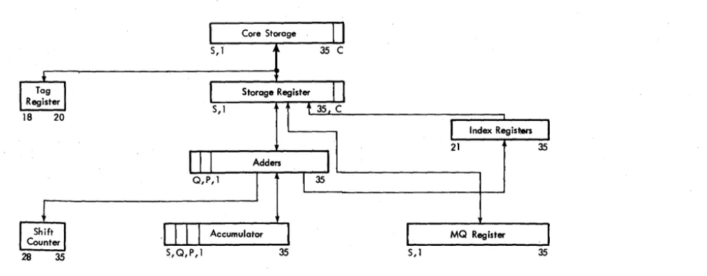
Instruction How charts accompany many of the instruc-tion descripinstruc-tions of this publicainstruc-tion. To aid under-standing the How of data and instructions through the processing unit, Figure 9 shows a simplified processing unit data· How; the positions of the word that are placed in an individual register or counter are shown below each component.
Input.Output Devices
The following sections describe the operation of input-output devices that may be attached to the system. In addition to the information about operation of keys and lights, general information about magnetic tape and basic card machine features is included.
[image:12.626.28.543.46.247.2]Magnetic Tape Handling
DUST PREVENTION
Foreign particles on tape can reduce the intensity of reading and recording pulses by increasing the dis-tance between the tape and the read-write head. Be extremely careful to protect magnetic tape from dust and dirt.
Keep the tape in a dust proof container whenever the tape is not in use on a tape unit. When a reel of tape is removed from a tape unit, immediately place it in a container. Always place sponge rubber grommets or special clips on the reels as they are stored, to pre-vent the free end from unwinding in the container.
When tape is removed from the container, close the container and place it where it is not exposed to dust and dirt.
Store tapes in a cabinet elevated from the floor and away from sources of paper or card dust. This should minimize the transfer of dust from the outside of the container to the reel during loading or unloading oper-ations.
Never use the top of a tape unit as a working area. Placing materials on top of the units exposes them to heat and dust from the blowers in the unit. It might
also interfere with the cooling of the tape unit.
To label a reel of tape for identification, other than by means of the provided card holder, use a material that can he removed without leaving a residue. Ad-hesive stickers that can be applied and removed easily are satisfactory. Never use an eraser to alter the identi-fication on a label.
DAMAGE PREVENTION
Information is recorded within .020 inch of the edge of the tape. Proper operation requires that the edge of the tape be free from nicks and kinks.
Handle reels near the hub whenever possible. In picking up reels, grip the reel between the center hole and the outer edge. Gripping the reel so as to com-press its outer edges pinches the few turns of the tape near the outer edge of the reel. Persons handling tape 'reels inside and outside the machine room should be instructed to avoid pinching the reels or contacting the exposed edges of the tape.
Dropping a reel of tape can easily damage both the reel and the tape. Never throw or mishandle reels even while they are protected in. their containers.
Magnetic Tape Units
CLEANING TAPE AND TAPE CONTAINERS
To clean a tape, gently wipe the tape with a clean, lint-free cloth moistened with an IBM recommended tape
transport cleaner.
Inspect containers periodically. Remove any accumu-lation of dust by washing with a regular household detergent.
TAPE BREAK
If a tape break occurs, divide the reel into two smaller reels. It may be necessary to make a temporary splice in order to recover information; however, splicing is not recommended as a permanent correction proce-dure. In making a temporary splice, be sure to use the special low-cold-flowing splicing tape.
DROPPED-TAPE INSPECTION
If a reel of tape has been dropped, the reel may be broken or bent. Bending is less likely, as a strain suffi-cient to bend a reel usually breaks it. The edge of the tape may be crimped, and the tape may be soiled. To test for and remedy these defects, proceed as follows:
1. Inspect the tape reel immediately. Breaking or bending of the reel can usually be found by visual in-spection. In addition, check the reel for bending by mounting 'it on the hub of a tape unit .. If the reel has been bent or broken:, it obviously should not be used again; but the tape may be serviceable.
2. Inspect the tape itself.
a. If there is no evidence of crimping or other tape damage, and the reel is undamaged, thoroughly clean the tape (exposed or unwound) and reel. The tape is then in good operating condition. If at all pos-sible, test to verify that the tape operates properly be-fore using it on subsequent runs.
b. If there is no evidence of tape damage, but the reel is damaged, thoroughly clean the tape (exposed or unwound) and rewind it on another reel. If pos-sible, test to verify that the tape operates properly.
c. If the edge of the tape is crimped, the action to be taken depends on whether the tape contains essen-tial information. If the tape does not contain essential information, discard the crimped footage. If the tape contains essential information, thoroughly clean the tape and attempt to reconstruct this information through a tape-to-printer or other machine operation. Should reconstruction fail, the records in question must be rewritten from cards or from another source.
Manual Operation of the Tape Units
On each tape unit, manual operations are performed
by using the keys and lights appearing in Figure 10. The tape address selector switch determines which
one of the tape addresses may select this unit. If the switch is set to 1, the unit may be addressed by 201 in the BCD mode or 221 in the binary mode. This switch
should not be rotated during any tape operation.
The select light is turned on only when the computer selects the tape unit. The ready light is on (the tape unit is in ready status), provided the tape is loaded in-to the columns, the reel door interlock is closed and
the tape unit is not in the process of finding the'load point (rewind or load operation). Manual control is
indicated when the ready light is off, provided the tape unit is not rewinding or loading and the reel door is closed.
Pressing the start key places the tape unit under
con-trol of the computer and causes the ready light to be turned on, provided the tape unit is in ready status. Pressing the reset key removes the tape unit from com-puter control, turns off the ready light, and resets all controls to their normal positions. It also stops any
tape operation that has been initiated, except high
speed rewind, which reverts to low speed rewind. After
the tape is loaded into the vacuum columns and
low-speed rewind is in progress, press the reset key again to
stop the low-speed rewind.
When the door is open, the reel door interlock pre-vents operation of the reel drive motors. If the reel door is closed and the ready light is off, pressing the load rewind key causes a fast rewind (if the tape is more than 450 feet from its load pOint) at the end of
Tape Address Selector Switch
Figure 10. mM 729 II and IV Keys and Lights
14
which the tape is loaded into the vacuum columns and
searched in a backward direction for the load point.
Pressing the unload key causes the tape unit to remove
the tape from the vacuum columns and raise the head
cover, regardless of the distribution of the tape on the two reels. If tape is not at the load point when the operator wishes to change it, the operator starts a load point search by pressing the load-rewind key.
The EOT indicators in the channel and tape unit are
turned on when the tape breaks or when the physical
end of tape is reached during a write operation. The end of tape test (ETT) may be used in a program to interrogate the status of the end-of-tape indicator in a
data channel. The status of the EOT indicator has no
effect upon tape operation.
The end-of-tape indicator and light may be turned
off by pressing the reset key on the tape unit and then
pressing the unload key on the tape unit. Execution of
the ETT instruction will turn off the EOT indicator in
the data channel.
The change density key changes the density mode (high or low) when depressed if the tape unit is not
ready. The stored program instruction can accomplish
the same density setting. The density mode in which
the tape unit is operating is indicated by the high or
the low density light.
The plastic tape reels are
lO
Vz
inches in diameterand are deSigned so that the front and back sides of
the reel are different (Figure 11). In normal operation,
a special ring is inserted in a groove in the back side
of the reel to depress a pin which is then under spring
tension. If the special ring is removed from the reel,
the pin rides freely in the groove and a writing int
Figure 11. Protect Ring
lock is automatically set. Also, the file protect light is turned on to inform the program that it is impossible for the program to write on tape. However, tape may be read, backspaced, or rewound freely when the file protect light is on.
The fuse light indicates that a fuse has burned out. Notify a customer engineer of this condition.
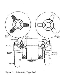
The tape transport mechanism of the 729u and 729IV tape units is shown in Figure 12.
Left Proloy ---lL.----1r---i""
,-"" 1
'--u
Figure 12. Schematic, Tape Feed
Tape Unload Procedures
To unload tape, use the following procedure:
1. Depress the reset key (tape unit) to tum off the ready light. Depressing the reset key is necessary only if the ready light is on.
2. Depress the load rewind key to rewind the tape. 3. When the load point has been reached, depress the unload key.
4. Open the reel door when the head cover is fully raised, the tape is out of the columns, and the load point is under the photoelectric cell. Do not open the door of the tape unit until the tape drive mechanism has completed the unloading sequence.
5. Bold the reel release key depressed and manually rewind the file reel by turning it in a counterclock-wise direction with the finger pressed in the finger hole of the reel.
6. When the tape has been completely rewound, loosen the hub knob and remove the reel. If resistance is encountered in removing a reel, exert pressure from the rear of the reel with the hands as near the hub as possible. Never rock a reel by grasping it near the outer periphery in such a way as to pinch the edges of the outer turns of tape.
7. Check the removed reel to determine whether it is to be file protected and whether it has been labeled correctly. Place the reel in the container. If the file protection ring has been removed and the file protect light fails to go on, notify the customer engineer im-mediately.
Tape Load Procedures
Before the follOwing tape load procedure is initiated, the tape unit should be in an unload condition and tape removed from the machine.
1. Check the reel that is to be loaded, to determine if if should have the file protection ring inserted or re-moved. The file protection ring must be inserted for card-to-tape operation. Mount the reel to be loaded on the left mounting hub and tighten the hub knob (Fig-ure 8). Place an empty reel on the right mounting hub and tighten the hub knob. The hub contains a rubber rim that grips the reel tightly when the knob in the center of the hub is tightened. When mounting, push the reels firmly against the stop on the mounting hub to insure proper alignment. Always make sure that the hub knobs have been tightened during loading. How-ever, do not use excessive force when tightening the hub knobs, for this tends to strip the threads.
2. Hold the reel release key depressed and rotate the file reel in a clockwise direction, unwinding about four feet of tape.
[image:15.627.70.259.61.253.2] [image:15.627.50.309.427.763.2]3. Place the tape over the left roller through the
read-write head assembly and over the right roller (Figure 8). Place and hold the end of the tape be -tween the index finger and the hub of the machine reel. Depressing the reel release key, wind the tape on the
machine reel in a clockwise direction for at least two
turns beyond the load point marker. When placing
tape on the machine reel, align it carefully to prevent damage to the edge on the first few turns. When wind-ing the tape to load point, rotate the machine reel with the finger in the reel finger hole or near the hub and on the reel. Rotating the reel with the finger in the cut
-out can result in nicking or curling the edge of the
tape ..
4. Close the reel door. Make sure that the door in-terlock switch is closed.
5. Set the address selector switch to the correct a d-dress position.
6. Depress the load rewind key to (1) load tape into the vacuum columns, (2) lower the head assembly,
and (3) rewind the tape to the load point.
7. Depress the start key. This places the tape unit under automatic control and turns on the ready light. OTE: Do not turn power off with the tape unit in
a load status because the head assembly must be up for removal of tape. If power is turned off after leaving
load point, it will be necessary to begin a new start procedure to resume operation.
. IBM
7330
Magnetic Tape Unit Keys and LightsFigure 13 shows keys and lights of the 7330, described as follows. Figure 14 shows both the IBM 729 II and
the IBM 7330 Magnetic Tape Units.
Address Selection Switch sets a tape unit to any one
of ten possible tape unit addresses.
Select Light turns on when the computer executes a tape control instruction that contains the tape address
Address Selection Switch Density SelecHon Switch
,fJ
_
_
a
e
. .
_
D1
1iii1i1_
Figure 13. IBM 7330 Operating Keys and Lights
corresponding to the setting of the address selectIOn switch of a unit that is ready.
Ready Light indicates that tape unit is in operation
or is ready for operation. The reel door should not be
opened when the ready light is on.
Tape Indicate Light turns on when the unit detects
a tape mark when reading, or an end-of-reel reflective
spot when writing. The light turns off after an unload operation and by instruction.
Fuse Light indicates that a protective device has in-terrupted an excessive flow of current; operation can
-not be resumed until the condition has been corrected by a customer engineer.
File Protection Light is turned on if the file reel is
mounted without a file protection ring in it or if the
unit is not ready or is rewinding. Writing on tape ca n-not occur when the file protection light is on.
Low Density Light turns on when density selection switch is manually set to low density. It must be on when the unit is reading or writing low-density tape.
High Density Light is turned on when the density
selection switch is manually set to high density; it must be on when the unit is reading or writing high-density tape.
Reset Key resets the tape unit to manual control and stops any tape operation previously initiated; it does not change status of the tape indicate light.
Stmt Key turns on the ready light and places the
tape unit in ready status. The start key is pressed only after tape has been positioned with the load-rewind key .
Low-Speed Rewind Key positions tape at the load point by causing a slow-speed (in-column) rewind until the load point marker is sensed. The low-speed rewind key is effective only if the load arm is posi-tioned, tape is in the vacuum columns, the reel door is closed, and the ready light is off.
High-Speed Rewind Key removes tape from the vacuum columns, raises the upper read-write head as-sembly, and rewinds tape at high speed. Tape must be in the columns, the reel door must be closed, and the ready light must be off for the high-speed rewind key to be effective. The tape indicate light is turned off at the end of the operation.
Density Selection Switch places the tape unit in low-density mode when the toggle is moved to the left and in high-density mode when the toggle is moved to the right. The appropriate density light turns on.
Reel Release Key is depressed to permit manually turning the reels for threading tape when the reel door is open.
Steps required to place a 7330 tape unit in ready status after a high-speed rewind are:
1. Open the reel door.
2. Press the reel release button and hold it pressed through step 5.
3. Manually rotate the take-up reel for a few times until the load point is on the reel.
4. Move the read-write head lever to a vertical posi-tion. This will lower the head.
5. Rotate each reel, as necessary, to move the tape into the vacuum columns properly.
6. Close the reel door.
7. Press the low-speed rewind and start keys.
TAPE LOADING PROCEDURE
Proper tape loading minimizes tape damage, tape con-tamination, and insures correct seating of the rewind arm:
1. Check for removal or insertion of file protection ring.
2. Place file reel firmly on machine mounting hub and tighten the hub knob.
3. Press reel release key and unwind about 18 inches of tape.
4. Open center cover and right column door. 5. Thread tape through tape transport as indicated on inside of center cover.
6. Close right column door.
7. Turn machine reel clockwise to move load point marker past the transport area; avoid slack in the tape.
8. Press reel release key and lower the rewind arm. 9. Remove pressure from reel release key for a few seconds.
10. After vacuum comes up, press reel release key and load tape into columns by turning the left reel clockwise and the right reel counterclockwise.
11. Seat rewind arm; close center cover and tape unit door.
12. Set the address selector switch to the correct ad-dress position.
13. Depress low-speed rewind and start keys.
7330 OPERATING PRECAUTIONS
High-Speed Rewind: To prevent damage to tape, never press the reset key or open the tape unit door during normal high-speed rewind.
If an emergency forces a violation of this rule, take steps afterward to remove undesirable tension from the tape on the file reel. Press the reel release key and manually wind at least 200 feet of tape from the file reel to the machine reel; then close the door and resume high-speed rewind.
High-Speed Rewind Arm: After tape is removed from the 7330, the high-speed rewind arm is in the up pOSition; leave it in the up position. An arm that is in the down position when power is turned off may cause fuses to blow when power is turned on.
Card Devices
IBM
1622 Card ReadPunch
The mM 1622 Card Read Punch reads 250 cards per minute and punches 125 cards per minute. Cards are read 9-edge first, face down, past two reading sta-tions: check and read. The read buffer is initially loaded with 80 columns of card data during a start or load run-in operation. Thereafter, each card feed cycle is under program control. The reader can accept and translate card codes equivalent to the 64 combi-nations of six bits (with optional feature).
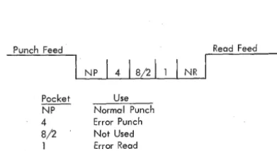
The read and punch feed units are separate and functionally independent; . each has its individual switches, lights, checking circuits, and buffer storage. Two stackers are provided for each feed unit: one for normal stacking, the other for error selected stacking (Figure 15).
Punch Feed Read Feed
NP
1
418/21
1I
NRPacket Use
~ Normal Punch 4 Error Punch 8/2 Not Used 1 Error Read N R Norma I Read
Figure 15. 1622 Card Read Punch Stacker Pockets
PUNCH HOPPER
POWER READY PUNCH READY FUSE
PUNCH STATION
~
PUNCH CHECK
CHIP II START II
TRANS-PORT
PUNCH
CHECK STATION
For the punch operation, cards are fed 12-edge first, face down, past the punch and check stations; All of the 64 combinations of six bits (with optional feature) can be translated and punched.
Card Read And Card Punch Keys and Lights (Figure 16)
The following lights are common to both the read and punch feeds:
Stacker Light is turned on when a stacker is full. Both feeds are stopped and removed from ready sta-tus .. Operation resumes after the stacker is emptied.
Fuse Light is turned on to indicate a blown fuse in the 1622.
Transport Light is turned on when a card in either feed unit does not feed properly. Both feeds are stopped and removed from ready status. Both start keys must be pressed to resume operation after the feed condition is corrected.
Thermal Light is turned on if the internal tem-perature of the 1622 becomes excessive.
CARD READER
Reader ani Off Switch supplies power to the unit. The computer power-on switch must be on to make this 1622 switch active.
N onprocess Runout Key is used to run out cards after a reader check error, or after the reader stop key
KEYS AND LIGHTS
i
I
I
I
I
READER
READER POWER CHECK READY READER READY STACKER THERMAL
READ STATION
CHECK
STATION READER
SELECT . / STATION
!l
HOPPER ,~I---I-~mCT
G
ATIONPUNCH PUNCH READ READ NON-SELECT
G G
NON- ERROR NOT USED ERROR SELECT SELECT SE LECT
[image:18.626.55.251.356.463.2] [image:18.626.37.545.497.758.2]has been pressed. The cards are placed in the read se-lect stacker without a buffer storage-to-core storage transfer. The reader check light and check circuits are turned off. Cards must be removed from the hopper to make this key active.
Poteer Ready Light is on when power in the 1622 is at an operating level.
Reader Ready Light is turned on to indicate that the first card has been loaded into buffer storage with the start key, without a reader check error. It remains on until: stop key is pressed, a reader check error, a transport jam, a misfeed, or an empty hopper.
Reader Check Light is turned. on by· an unequal comparison between the read and check stations and by incorrect parity detected in buffer storage during a card read. With an unequal comparison, the reader is stopped, ready status is terminated, and the buffer storage data just read cannot be transferred to core storage on the next read operation.
Start Key is used (1) to run in cards which are then placed under program control (data from the first card is checked and loaded in input buffer stor-age); (2) to set up a runout condition, which per-mits programmed reading of the cards remaining in the feed when the hopper becomes empty; and (3) to restore ready status after the reader has been stopped by either the stop key, an empty hopper, an error, a misfeed, or a transport jam.
Stop Key is used to stop the read feed at the end of the card cycle in progress, and to remove the reader from ready status. Data that is entered into buffer stor-age during the read cycle in progress is transferred to core storage. The computer continues processing until the next read instruction causes a reader-no-feed stop. Load Key causes data from the first card to be read into buffer storage and to be checked. Thereafter, each card feed cycle is under program control.
CARD PUNCH
Punch On/Off Switch supplies power to the unit. The computer power-on switch must be on to make this 1622 switch active.
Select N -Stop - Select Stop Switch controls stop-ping of the punch when error cards are selected into the punch error select stacker. With the switch on
STOP, the punch feed stops with the error card in the
select stacker.
--Nonprocess Runout Key is pressed, after a punch check error and machine stop, to reset the error
cir-~~~~~ CHIPS PUNCH CHECK PUNCH STOP
Figure 17. IBM 1402 Keys and Lights (Model 2 )
STACKfi POttER
FUSE TRANSPORT
cuits and to run out the card (B) following next be-hind the error card (A). Card B has passed the punch station and is stopped between the punch and the punch check stations. Card B may have been the sub-ject of a punch error at approximately the same time as the punch check error on card A; if so, card B will follow card A into the select stacker and the punch check light will be turned on again. The next follow-ing two cards will be blank and will go into the non-select pocket; these two cards should be removed before further processing.
Punch Ready Light is turned on when the 1622 has a card in punching. position and will respond to a write instruction. The light is turned off by a punch check error, an e'mpty hopper, a full chip box, a stop key depression, a transport jam, or a misfeed.
Power Ready Light is on when power in the 1622 is at an operating level.
Punch Check Light is turned on by an unequal comparison between data read at the check station, and data punched on the preceding card feed cycle; or when, with the select stop switch set to stop, a 1622 parity error occurs during punching. The punch stops and ready status is terminated.
Start Key is used to feed cards to the punch sta-tion initially or after an error and nonprocess runout; and to establish ready status after an empty hopper, a misfeed, a transport jam, or a stop key depression. Stop Key is used to stop the punch feed at the end of the card cycle in progress, and to remove the punch from ready status.
Check Reset Key is used to reset error circuits and turn off the punch check light. A start key or non-process runout key depression must follow.
IBM 1402 Card Read Punch,
Model
2
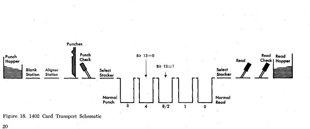
The 1402, Model 2, reads 800 cards per minute and punches 250 cards per minute. The read and feed units are separate as with the 1622, and the same stacker pocket names are used. The 8/2 pocket, used only on the 1402, holds selected punched cards. Cards are read and punched in the same manner as with the 1622.
Card Read Punch Lights (Figure 17)
The 1402, Model 2, has four lights that refer to the machine rather than to one of the two units:
VALIDITY ~~~; READER CHECK READER STOP
~
L.&J
Stacker indicates that one or more pockets are full. Both the reader and punch units stop.
Fuse indicates that a fuse has blown in the reader or punch unit.
Power indicates that power is being supplied to the 1402.
Transport indicates that a card jam has occurred in the stacker transport area. Card feeding is stopped in both feeds until the jam is cleared.
Reader Keys and Lights
READER START
Operating this key feeds three cards into the read feed, fills the reader synchronizer with the contents of the first card, and turns on the reader ready light.
When the reader has been stopped, pressing the start key turns on the reader ready light, and allows the cards to continue feeding under program control. When the cards are removed from the read feed hopper and the end-of-file key is not operated, press-ing the start key moves the remainpress-ing two or three cards to the NR stacker pocket unprocessed (Figure 18).
READER STOP
Operating this key stops the reader at the end of the feed cycle in progress and turns off the reader ready light.
END-OF-FILE (EOF)
Operation of this key activates circuits that signal a last card condition in the central processing unit. The last card condition can be used by the stored program to initiate an end-of-file routine. The end-of-file latch is turned on following the data transfer of the last card. The EOF key lights when it is pressed.
Punches
The end-of-file key, which can be pressed at any time, causes the card reader to operate in one of these ways:
1. With four or more cards in the read hopper, all the cards are processed and run into a stacker. Operat-ing the stop key or processOperat-ing the last card causes the end-of-file condition to be reset.
2. With three cards remaining in the feed, a card read instruction before the operation of the end-of-file key causes the program to hang-up. Pressing the end-of-file key and then the start key allows the last three cards to be processed and run into a stacker. Operating the stop key or processing the last card causes the end-of-file condition to be reset.
3. With the one, two, or three cards to be processed in the read hopper, pressing the end-of-file key and then the start key feeds the card or cards and turns on the reader ready light after the first card passes the second read station. The card or cards are processed and run into a stacker. Operating the stop key or proc-essing the last card causes the end-of-file condition to be reset.
READER READY
This light indicates that the reader is ready to be used by the CPU.
VALIDITY
This light indicates than an invalid character has been detected during a feed operation. The light remains ON
until the next feed instruction is started. During the read instruction, the invalid character is transferred from synchronizer to storage.
READER STOP
This light indicates that a feed failure or card jam has occurred during a feed operation, stopping the reader and turning off the reader ready light.
Hopper
tf
I
Blank~
Aligner
Station
1
~~:~t
Bit 11
3=0
~
Bit 13=1~~ ~~
Stacker
+
Stacker:aUUUUU=
Read
21
Punch Read
o 4 8/2 0
[image:20.621.34.563.528.749.2]READER CHECK
This light indicates the detection of a hole count error, parity error, or synchronizer timing error during a feed operation. The light remains ON until the next feed
instruction is started. During the read instruction, the data are transferred from synchronizer to storage, and the channel A redundancy check indicator is turned on.
Punch Unit Keys and Lights
PUNCH START
Operating this key feeds two cards into the punch feed and turns on the punch ready light.
When the punch has been stopped, pressing the start key turns on the punch ready light, and allows card punching to resume under program control.
When the cards have been removed from the punch feed hopper, pressing the start key moves the three cards remaining in the punch feed to the normal punch pocket. The first card that enters the normal punch pocket is unchecked.
PUNCH STOP
Operating this key stops the punch at the end of the feed cycle in progress and turns off the punch ready light.
PUNCH READY
This light indicates that the punch is ready to be used by the CPU.
PUNCH STOP
This light indicates that a feed failure or card jam has occurred during a punch operation, stopping the punch and turning off the punch ready light.
PUNCH CHECK
This light indicates the detection of a hole count error, parity error, or synchronizer timing error during a punch operation.
CHIPS
This light indicates that the chip receptacle is full or not in place. The punch cannot operate while the chips light is on.
NOTE: Cards in either the punch or reader ~hich
result in validity errors or a hole count check are automatically stacked in the NP or NR pocket.
Printer
IBM 1403 Printer, Models 1
and
2
The 1403, Modell or 2, is an output unit for IBM 7040
and 7044 systems. The standard printing capacity is 100 positions, with an additional 32 positions available on the Model 2. Each position can print 48 different characters: 26 alphabetic, 10 numeric, and 12 special characters. For information pertaining to the numeric print feature, refer to "Special Features" at end of this section.
METHOD OF PRINTING
The alphabetic, numeric, .and special characters are as-sembled in a chain (Figure 19). As the chain travels in a horizontal plane, each character is printed when it is positioned opposite a magnet-driven hammer that presses the form against the chain.
When each character is printed, it is checked against the corresponding position in the print synchronizer to insure that printed output is accurate. Also, the ma-chine checks to insure that the character is printed in the correct print position, that only valid characters are printed, and that over-printing does not occur.
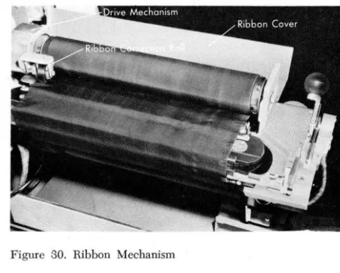
Ribbon
132 Printing Positions
Figure 19. Printing Mechanism, Schematic
22
1403 Printer Keys and Lights (Figures 20 and 21)
PRINTSTART (FRONT AND BACK)
Operating this key turns on the ready light.
PRINT STOP (FRONT AND BACK)
Operating the stop key turns off the ready light. If the stored program attempts to execute a WRS instruction
with the printer specified, the CPU will hang up. CHECK RESET
This key resets a printer error indication. The print-start key is then pressed to resume operation.
PRINT READY
This light indicates that the printer is ready to print.
END-OF-FORMS
This light indicates an end-of-forms condition (the machine stops).
FORMS CHECK
This light indicates paper feed trouble in the forms tractor, or that the carriage stop has been used. This
Paper
[image:22.627.41.564.423.771.2]PRINT PRINT
READY CHECK
END or FORMS
-..
FORMS SYNC...
CHECK CHECKFigure 20. 1403 Operating Keys and Lights
light must be cleared by the check reset key before the print start key is effective.
PRINT CHECK
This light indicates a print error.
SYNC CHECK
This light comes ON to show that the chain was not
in synchronism with the printer compare counter. The timing is automatically corrected. The light is
extin-guished by operating the print start key.
1403 Carriage Controls
CARRIAGE RESTORE
Pressing