\
j
I•
-- -- -- --
- -
-
- - -
--
- -
-
-
---
---
---_
.
-GA34-0028-1
File
No. S1-09
IBM Series/1
Communications Features
Description
'[OT'-,
".
~
~
~Vl~!8iJ
II ' - -I
Series/1
0 ~ :[Jcl
10
II
11111111111111111111111111111111111111111111111
0
[])
111111111111111111111111111111111111111111111111
0
[]
0[]J
1111111111111111111
~
0 [[]JI
-
111111111111111111111111111111111111111111111111I
{(I
z..
=
~
-- -- --
-- -- -- --
-
- - - --
--
----
-
-
---
---
--_.-(
c
GA34-0028-1 File No. S1-09
IBM Series/1
Communications Features
Description
Second Edition (March 1977)
This is a major revision of, and obsoletes GA34-0028-0. Significant changes in this new edition include:
1. Chapters 2, 3, and 4 have had descriptions of the jumperable options added. 2. A new appendix (Appendix C) has been added.
3. Technical corrections have been made. These changes are marked by a vertical bar to the left of the affected areas.
Changes are periodically made to the information herein; any such changes will be reported in subsequent revisions or Technical Newsletters. Before using this publication in connection with the operation of IBM systems, have your IBM representative confirm editions that are applicable and current.
Requests for copies of IBM publications should be made to your IBM representative or the IBM branch office serving your locality
A form for readers' comments is provided at the back of this publication. If the form has been removed, send your comments to IBM Corporation, Systems Publications, Department 27T, P.O. Box 1328, Boca Raton, Florida 33432. Comments become the property of IBM.
©Copyright International Business Machines Corporation 1976, 1977
(
(
c
Preface v
Prerequisite Publications v Related Publications v Summary of Publication v
Chapter 1. Introduction 1·1 Summary Description 1·1
Communications Features 1·1 Interfaces 1·1
Types of Data Links 1·2 Transmission Codes 1·3 Communications Indicator Panel 1-4 Communications Facilities 1-4
Chapter 2. Asynchronous Communications Control Features 2·1
Section One. Product Description 2·1 ACC Feature Configurations 2·1 Line Control 2-2
Control Characters 2·2 Transmission Codes 2-4
PTTC Codes for 2740 and 2741 2-4 Eight Bit Data Interchange Code 2-4 Data Flow 2-4
Line Error Checking 2·5 Timeouts 2-5
Operating Modes 2·5 Commands 2·5
Prepare 2·5 Device Reset 2·6 Start 2·6
Start Cycle Steal Status 2-6 Read ID 2·6
Diagnostic Commands 2·6 Start Control 2·7
Device Control Block (DCB) 2·7 Control Word 2·8
Bit-Rate Constant 2-11 Line Control Characters 2-12 Timer 1 2-12
Timer 2 2-12 Chain Address 2·12 Byte Count 2·12 Data Address 2·12
Interrupt Status Byte (lSB) 2·12 Cycle Steal Status Words 2·13
Word Zero 2·13 Word One 2·13 Word Two 2-14 Status After Resets 2·14 Jumperable Options 2-15
Asynchronous Communications Single·Line Control Feature 2·15 Asynchronous Communications 4·Line Adapter feature 2-15
Contents
Section Two. Asynchronous Communications Features Operating Procedures 2·16
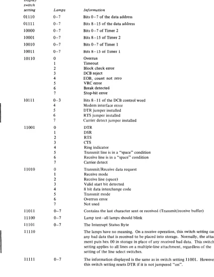
Communications Indicator Panel 2·16 Line Select Switches 2-16 Function/Display Switches 2·16 Error Recovery 2-18
Chapter 3. Binary Synchronous Communications Features 3·1
Section One. Product Description 3·1 BSC Feature Configurations 3·2 Data Transmission Codes 3·3 Data Flow 3·3
Transmit 3·3 Receive 3·3
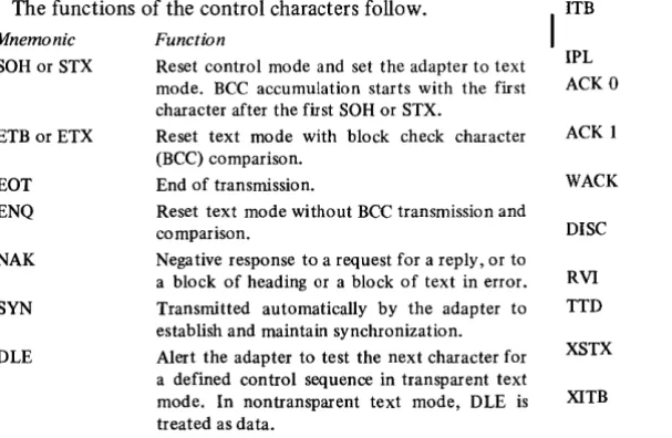
Control Characters and Sequences 3·4 Line Error Checking 3·5
Synchronization and Timing Information 3·5 Transmit Synchronization 3-5
Receive Synchronization 3·5 Timeouts 3-5
Data Set Ready Timeout 3·5 Receive Timeout 3-5 Program Timeout 3-5 Operating Modes 3·6
Text Mode 3·6
Transparent Text Mode 3·6 Control Mode 3·6 Selected Mode 3·6 IPL Mode 3·6 Commands 3· 7
Prepare 3·7 Device Reset 3· 7 Start 3·8
Start Cycle Steal Status 3·8 Read ID 3·8
I
Diagnostic Commands 3·8 Start Control 3·8Device Control Block (DCB) 3·9 Control Word 3-9
Chain Address 3·10 Byte Count 3-10 Data Address 3·10
Interrupt Status Byte (lSB) 3·10 Cycle Steal Status Words 3·11
Word Zero 3·11 Word One 3-11 Word Two 3·12 Status After Resets 3·12 Jumperable Options 3·12
Binary Synchronous Communications Single-Line Control (Medium Speed) 3·12
Binary Synchronous Communications Single·Line Control/ High Speed 3·13
Binary Synchronous Communications 4-Line Adapter 3·13
Section Two. BSC Operating Procedures 3-14 Communications Indicator Panel 3-14
Line Select Switches 3-14 Function/Select Switches 3-14 Error Recovery 3-18
Operate I/O Condition Codes 3-18 Interrupt Condition Codes 3-18
Otapter 4. Synchronous Data Link Control Single-Line Control Feature 4-1
Section One. Product Description 4-1 SDLC Feature Configurations 4-1 Data Transmission Codes 4-1 Data Flow 4-2
Transmit 4-2 Receive 4-2
Control Characters and Sequences 4-3 Frame Format (F, A, C, I, FCS, F) 4-4
Flag 4-4
Zero Insertion 4-4 Idle Stations 4-5 Address Field 4-5
Control Field and the P/F Bit 4-6 Information Field 4-7
FCS (Frame Check Sequence) Field 4-7 Synchronization 4-7
Timers 4-8 Timer 1 4-8 Timer 2 4-8 Operating Modes 4-8
Monitor Mode 4-8 Receive Mode 4-8 Transmit Mode 4-9 Commands 4-9
Prepare 4-9 Device Reset 4-10 Start 4-10
Start Cycle Steal Status 4-10 Read ID 4-10
Diagnostic Commands 4-11
Device Control Block (DCB) 4-11 Control Word 4-11
Timers 4-13 Status Address 4-13 Chain Address 4-14 Byte Count 4-14 Data Address 4-14
Interrupt Information Byte (lIB) 4-14 Interrupt Status Byte (ISB) 4-14 Cycle Steal Status Words 4-15
Word Zero 4-15 Word One 4-15 Word Two 4-15 Word Three 4-16 Status After Resets 4-16
I
Jumperable Options 4-16Section Two. SDLC Feature Operating Procedures 4-17 Communications Indicator Panel 4-17
Line Select Switches 4-17 Function/Display Switches 4-17 Error Recovery 4-18
Operate I/O Condition Codes 4-18 Interrupt Condition Codes 4-18
Appendix A. Reference Information A-I
Appendix B. ACC Features Operational Flowcharts B-1
Appendix C. Cable Information C-I
Index X-I
I )
,
,
(-(
(
c
This manual describes the functional characteristics of the IBM Series/l communications features. It is assumed that the reader understands data processing terminology and is familiar with binary and hexadecimal numbering systems. This publication is intended primarily as a reference manual for experienced programmers who require machine code information to plan, correct, and modify programs written in assembler language.
PREREQUISITE PUBLICATIONS
• IBM Series/l Model 5, 4955 Processor and Processor Features Description, GA34-0021; or IBM Series/l Model 3, 4953 Processor and Processor Features Description, GA34-0022.
• IBM Systems Reference Library: General Information-Binary Synchronous Communications,
GA27-3004.
• IBM Synchronous Data Link Control General Information, GA27-3093.
RELATED PUBLICATIONS
• IBM Series/1 Installiltion Manual-Physical Plilnning,
GA34-0029.
• IBM Series/1 Configurator, GA34-0042.
Preface
SUMMARY OF PUBLICATION
Chapter one contains a general description of the three general types of communications features available for the Series/I. Chapter two-Asynchronous communications fea t ures. Chapter three - Binary Synchronous communications features. Chapter four-Synchronous data link control communications features.
Chapters two, three, and four are each divided into two sections. Section 1 contains descriptions of commands, immediate device control blocks (IDCBs), device control blocks (DCBs), operations, and status information. Section 2 contains information on error recovery and the use of the
Communications Indicator Panel feature.
Appendix A contains a character code chart for ASCII, EBCDIC, Eight Bit Data Interchange, and PTTC codes. In addition to the code chart, Appendix A contains charts showing line control characters for the IBM 2740 and 2741, ASCII line control characters, sample BSC IPL sequence, and condition code charts.
Appendix B contains flowcharts of the various operations tha t can be performed by the asynchronous communications features.
Appendix C contains diagrams of various cables used to connect the communications features to modems or terminals.
(
c
The Series/l communications features are designed to provide a variety of communications options. The features are the Synchronous Data Link Control Single-Line Control feature (abbreviated SDLC). the Binary Synchronous Communications feature (BSC), and the Asynchronous Communications Control feature (ACC).
All three features provide the capability to communicate with telecommunication terminals and host systems. Only the single-line BSC features are capable of receiving an Initial Program Load (IPL) from a host system.
SUMMARY DESCRIPTION
The features provide a variety of single-line and
multiple-line telecommunications capability. In addition, there is a variety of line speeds, line configurations, clocking sources and data codes to choose from. All communications features described in this manual are cycle-stealing devices.
Communications Features
Asynchronous Communications Single-Line Control
Feature
This feature provides circuitry for one half-duplex line. It
can operate at speeds up to 9,600 BPS (bits per second). It
can be used as either a primary station or a secondary station. The ACC makes no provisions for station-address recognition. Therefore, when ACC is used as a secondary station on a multipoint network, the software must provide the ability to recognize station-addresses. No IPL capability is provided.
Asynchronous Communications 8-Line Control and
Asynchronous Communications 4-Line Adapter Features A maximum of eight lines operating half-duplex may be controlled by these features. The bit-rate for each of these lines is a maximum of 2,400 bits per second.
Chapter 1. Introduction
Binary Synchronous Communications Single-Line Control Feature
This feature provides circuitry for one half-duplex, medium speed (up to 9,600 bits per second) line. It also provides the ability to IPL (initial program load) the processor from a host system. This feature can be used as either a primary (control) or secondary (tributary) station.
Binary Synchronous Communications Single-Line Control/ High Speed Feature
This feature provides circuitry for one half-duplex, high
speed (up to 56,000 BPS) line. It also provides the ability
to IPL the processor from a host system. This feature can be used as either a primary or secondary station. This feature is for use in leased-line applications only.
Binary Synchronous Communications 8-Line Control and Binary Synchronous Communications 4-Line Adapter Features
These features can control up to eight half-duplex communications lines at medium speeds. The maximum aggregate bit-rate possible through the 8-line control feature is 33,600 BPS. The ability to IPL from a host system is not provided on multiple-line BSC features.
Synchronous Data Link Control Single-Line Control Feature
This feature provides circuitry for one half-duplex line. This line can handle bit-rates up to 9,600 bits per second (BPS). The SOLC feature operates as a primary station or a
secondary station but provides no IPL capability.
Interfaces
In all features except the high speed BSC, an EIA
*
RS232-C and CCITT (Consultive Committee on Inter-national Telephone and Telegraph) V.24 interface is pro-vided for each line. The interface directly drives or terminates an external modem. The high speed BSC provides interfaces compatible with the Western Electric 303 Data Set (or equivalent), and CCITT recommendation V.35.
*
Electronic Industries Association 2001 Eye Street, N.W.Washington, D.C. 20006
Types of Data Links
Each communications line can operate in one of three different types of data link. The data links are:
• Point-to-point-non-switched • Point-to-point-switched • Multipoint
A line is point-to-point when a local station is connected
to a single remote station. Such a line is non-switched when
there is a permanent connection between the local sta tion and the remote station through their respective modems, or when the stations are directly connected.
Local
Modem* Station Modem*
* Modems not present when using direct connect cable with the ACC feature.
Point-to-point netwurk-nonswitched
A point-to-point line can be switched so that one local
station can communicate with one of several remote
stations after a link has been established between the local station and the remote station. The connection is maintained only for the duration of the communication.
Local
Station Modem
Point-to-point network-switched
I
I
\
••
\
\
Modem
Modem
Modem
Remote Station
Remote Station
Remote Station
c
(
c
The primary station in a multipoint data link is physically
connected to several secondary stations through their respective modems. The primary station polls the secondary stations using unique station addresses. Only the addressed station can respond to the poll.
Modem
Control
Modem Modem
Station
Modem
Multipoint network
Transmission Codes
The communications features can use a variety of transmission codes.
ACC Codes
The ACC features can use the following codes: • PTTC/EBCD
• PTTC/Correspondence • Eight Bit Data Interchange BSC Codes
The BSC features can use the following codes: • ASCII
• EBCDIC (transparency is standard) SDLC Codes
Full transparency is inherent in SDLC procedures. The
SDLC feature can use any eight-bit code including the
following codes: • ASCII • EBCDIC
Tributary Station
Tributary Station
Tributary Station
COMMUNICATIONS INDICATOR PANEL
The Communications Indicator Panel is available as an option to the communications features. This panel provides a means of displaying various states, conditions, and lines.
It also provides a means of manually resetting the 'data
terminal ready' line to the modem.
o
2 3 4 5 6 700000000
@ \ 6 8 4 2 1 4 2
10
Q~QQQQOQ
I
DISPLA Y jFUNCfIONI
L
LINE I L - . - _ _ _ SELECT - - - I SELECf---.1
The indicator panel may be used with any of the communications features one at a time. The panel's cable plugs into a connector on a feature control card, and the panel can be moved between processor units and I/O expansion units. Therefore, it is not necessary to have more than one indicator panel. The panel does not attach to the 4953 models A and C.
The indicator panel provides different information for each feature. Detailed information about the indicator panel is given in the chapter for each feature.
COMMUNICATIONS FACILITIES
The communications features can communicate with remote stations over private lines, leased common-carrier facilities, or switched voice-grade common-carrier lines.
The ACC, the SDLC, and the medium speed BSC interfaces conform to the Electronic Industries Association (EIA) standard RS232-C, and to the Consultive Committee on International Telephone and Telegraph (CCITT) recommendation V.24.
The high speed BSC provides the ability to select either an interface that is compatible with a Western Electric 303 (or equivalent) data set, or an interface that is compatible with CCITT recommendation V.35.
Some modems automatically disconnect when the communication feature's 'data terminal ready' (DTR) signal is deactivated. This signal can be deactivated by issuing a Start command with a "disable" operation specified in the
I
DeB, or by using the communications indicator panel.-(
(
c
Chapter 2. Asynchronous Communications Control Features
Section One. Product Description
The Asynchronous Communications Control (ACC)
features are optional features which control transfer of serial data to and from remote terminals or host systems via
modems and communications line facilities- The ACC
features allow the processor to communicate with telecommunications equipment using the start/stop method of data transfer. There are several important items to consider about the ACC features. They are:
• Data transmission is serial-by-bit, using the start/stop method of character and bit synchronization.
• The features can communicate with several different terminals using one of two transmission codes.
• The selection of a code is under program control. • tine control characters are defined by the program. • Bit rates from 37.5 to 9,600 bits per second (BPS) are
controlled by programming. The multiple-line ACC feature can handle up to 2,400 BPS on all eight lines. • The ACC features make no provision for station-address
recognition. Therefore, when an ACC feature is used as a secondary station on a multipoint network, the software must provide the ability to recognize station-addresses. • The processor cannot receive an initial program load
(IPL) through the ACC features.
• The features provide answertone generation.
Indicator panel connectors
3
Device
addres~
!
XXXXXOI1/1 XXX X XOIO
XXXX XOO 1 -- 11
XXXXXOOO~
o
ACC FEATURE CONFIGURATIONS
The Asynchronous Communication Control features are available in single-line and multiple-line configurations. The multiple-line configuration provides up to eight lines. The
single-line ACT feature contains one card. The multiple-line
configuration contains either two or three feature cards-two cards for one to four lines, three cards for five to eight lines.
Note. Throughout the remainder of this chapter, the term
attachment is used as a general term to refer to either of the following:
1. The Asynchronous Communications Single-line
Control feature.
2. The Asynchronous Communications 8- tine Control
feature and on~ or two Asynchronous Communications
4-line Adapter features.
When referring specifically to item 1 above, the term
single-line attachment is used. When referring specifically to
item 2, the term multiple-line attachment is used.
Each line operates in a half-duplex mode. If desired, each line can be connected to a full-duplex modem to avoid modem turnaround times. If a line is connected to a full-duplex modem, the attachment still operates in half-duplex mode.
7
6
~
Device address~XXXXXlll
XXXX XII0 S _ _ XXXXXI0l XXXX XI00
4 /
Asynchronous communication single-line control
Asynchronous communication 4-line adapter
Asynchronous comm unica tion 8-line control
Asynchronous communication 4-line adapter
*
Modem interface connectorsLINE CONTROL
A precise exchange of control characters between stations is necessary to establish and maintain teleprocessing communications. This exchange of control characters is called line control. One of its functions is to prevent two or more stations or terminals from attempting to use the line simultaneously (line contention).
Because each remote terminal may require different line control characters, the ACC attachments provide programmable line control characters. These characters are transferred to the attachment via the DCB (device control block). The DCB that transfers the control characters to the attachment is different from other DCBs. It is identified by bits 12-15 of the control word being set to 1101.
Control Characters
On a transmit operation (using PTTC code), the attachment compares characters coming from the processor with the programmed line control characters. On a receive operation, the attachment compares the characters being received with the programmed line control characters. All recognized control characters, that cause a change of direction (COD), cause the attachment to terminate the operation in progress with either a normal device end interrupt, a DCB command chaining operation, or an exception interrupt with ISB bit 0 on. All received control characters, except upshift and downshift, are placed in storage.
The attachment recognizes the control characters and acts on them as follows:
Eight Bit Data Interchange Code-Receive Mode
The attachment recognizes any of the seven characters defmed in the DCB and treats them as COD characters. When any of the defined characters is received, the attachment presents a device end interrupt or begins a DCB command chaining operation (except when an Incorrect
Length Record* is detected).
Eight Bit Data Interchange Code-Transmit Mode
There is no control character recognition in transmit mode. All ending conditions must be controlled by byte count. A device end interrupt occurs when the byte count is decremented to zero.
*
See INTERRUPT STATUS BYTE.PlTC Code-Receive Mode
When it is desired that the attachment operate in PTTC mode, the program should initiate a Set Control operation, specifying the control characters in the DeB as follows:
Word ,2.CB ~vic£50.1!trol bloctl - - -
-1
o
I
,
,---I /16 (EOA)
2 /3D (EOB) /76
<
G)
3 /40
<0 )
/IF©,
(EOT)4 /IC (Upshift) /7C (Downshift)
5
I
It--- - -
---~
6
I
I
~---.~
7
I
I
EOA
EOB
L _ _ _ _ _ _ _ _ _ _ _ _ _ _ _ _ _ I
o 15
This is the low order byte of word 1 of the Set Control DCB.
When the first EOA character (end of address) is received, the attachment begins LRC (longitudinal redundancy check) character accumulation starting with the next character to be received. The EOA character is placed into storage.
This is the high order byte of word 2 of the Set Control DCB.
When this character (end of block) is received, the attachment compares the next character, which is the LRC character, with the LRC character generated by the attachment. If the LRC characters compare, the attachment terminates the operation with a normal device end interrupt or begins a DCB command chaining operation (except when an Incorrect Length Record* is detected). If the LRC characters do not compare, or if there is a stop-bit error or VRC error, the attachment terminates the operation with an exception interrupt and sets ISB bit 0 "on," indicating that information as to the cause of the error is available to the program.
Note. The attachment makes no distinction between terminals that use record checking and terminals that do not use record checking. Therefore, the EOB must not be received when record checking is not used.
(
-(~
(
COD I COD 2
COD 3
Upshift
Downshift
These are: the low order byte of word 2 and the high order byte of word 3 in the Set Control DCB. For PTTC code, one of these bytes should be loaded (by the program) with the positive acknowledgement character
(X)
and the other byte should be loaded with the negative acknowledgement character ( ® ) .If the attachment is in Receive mode, it does not recognize any COD 1 or COD 2 character that occurs between an EOA and an EaT -the characters are simply treated as data. Receive mode is used for receiving data. Receive Response mode is used after a transmit operation to allow recognition of the positive or negative response from the station that received the data. Receive Response is only used where record checking is being performed. If the attachment is in Receive Response mode, it recognizes the COD I and COD 2 characters at any time. When the attachment recognizes a COD I or COD 2, it places the character in main storage and presents a device end interrupt (except when an Incorrect Length Record* is detected). The program then must examine the character in storage and determine the appropriate action.
This is the low order byte of word 3 in the Set Control DCB.
For PTTC code, this byte should be loaded (by the program) with the
©
(EaT) character. When the defined character is recognized, the attachment terminates the operation with a device end interrupt or begins a DCB command chaining operation (except when an Incorrect Length Record* is detected).This is the high order byte of word 4 in the Set Control DCB.
For PTTC code the program should load the value IC (hexadecimal) into this byte. When this character is recognized, the character itself is not placed in storage. The attachment places subsequent characters into storage with the high order bit of each byte on, until a downshift or COD character is received, or until the attachment is reset.
This is the low order byte of word 4 in the Set Control DCB.
For PTTC code the program should load the value 7C (hexadecimal) into this byte. When this character is recognized, the character itself is not placed in storage. The attachment places subsequent characters into storage with the high order bit of each byte off, until an upshift character is received. All receive operations begin in lower case.
*
See INTERRUPT STATUS BYTE.PTTC Code-Transmit Mode
In this mode all normal ending conditions must be controlled by the byte count.
EOA
EOB
COD I COD 2
COD 3
Upshift Downshift
This is the low order byte of word 1 in the Set Control DCB.
When this character (end of address) is recognized, the attachment begins LRC accumulation starting with the next character transmitted. Any characters with the same bit configuration as the EOA, occurring between the first EOA and the COD 3 character, are treated as data.
This is the high order byte of word 2 in the Set Control DCB.
When this character (end of block) is recognized, the attachment transmits the EOB and follows it with the LRC. If the byte count is zero when the EOB is transmitted, the attachment presents a device end interrupt or begins a DCB command chaining operation. If the byte count is not zero, the attachment terminates the operation with an exception interrupt and sets bit 0 on in the ISB and bit 4 on in cycle steal status word one. Note. The attachment makes no distinction between terminals with record checking and terminals without record checking. Therefore, the EOB must not be transmited when record checking is not used.
These are: the low order byte of word 2 and the high order byte of word 3 in the Set Control DCB. Any COD 1 or COD 2 character coming from storage is simply transmitted as data.
This is the low order byte of word 3 in the Set Control DCB.
In transmit mode, when the attachment recognizes this character, it is again able to recognize the EOA character as an EOA.
These are: the high order byte and the low order byte of word 4 in the Set Control DCB.
On outgoing data, the shift bit (bit 0 of each byte) is noted and removed from each character. A change in the shift bit causes the appropriate shift character to be inserted into the data stream before the data character is sent.
Note. The attachment does not recognize the shift characters as they come from storage so it does not update the shift mode unless the shift bit accompanying the shift character indicates a change. If the bit changes the current case, two shift characters are transmitted.
TRANSMISSION CODES
The ACC attachments can serve as control stations to a variety of terminals by using one of the following codes:
• PTTC/EBCD
• PTTC/Correspondence Code • Eight Bit Data Interchange Code
Line control depends on the requirements of the terminal. For detailed descriptions of terminal line control, consult the technical manual for the terminal.
PTTC Codes for 2740 and 2741
Character Set
The IBM 2740 Models 1 and 2 and the IBM 2741 use two versions of PTTC code. They are PTTC/EBCD code and PTTC/Correspondence code. These codes are similar, but they have some differences in character' structure and line control usage. The codes are shown in Appendix A.
Line Control Characters
The line control characters used by the 2740/2741 are shown in Appendix A.
Eight Bit Data Interchange Code
Eight Bit Data Interchange Code is essentially a mirror image of eight bit ASCII. Therefore, the ACC features may communicate with terminals that use 8 bit ASCII code (such as Teletype ASR 33 and ASR 35). These terminals,
Transmit ... __
----1--Data
Storai!e 0 2 3 4 5
PTTC * B A 8 4 2 8 bit DIC 2 3 4 5 6
*Shift bit
First character
6
7
however, must transmit two stop bits to preclude stop-bit errors in the attachment.
Character Set
The character set for Eight Bit Data Interchange Code is shown in Appendix A.
Line Control Characters
The line control characters for Eight Bit Data Interchange Code are shown in Appendix A.
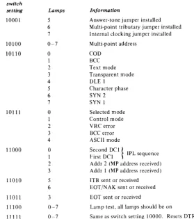
DATAFLOW
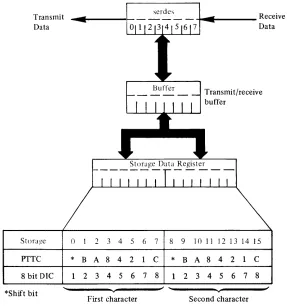
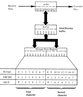
With the exception of the upshift/downshift bit, valid data is placed in storage as it is received. Data received containing bad parity or a stop-bit error is replaced in storage with hexadecimal 00. Data is transmitted exactly as it comes from storage. Therefore, data must be organized in the exact bit configuration required by the code being used and in the sequence in which it is to be transmitted. Figure
2-1 illustrates the relationship between (1) bits in storage,
(2) the various transmission codes, and (3) the attachment's storage data register.
Note.
ACC attachments transmit by sending out the high order bit of the high order byte first. The received characters are stored in the same manner-the first bit received is the high order bit of the high order byte. If the data address (DCB word 7) is odd, only one character will be moved in or out of storage on the first data transfer.serdes
Buffer
7 8 9
C
*
B8 1 2
... _ _ _ _ Receive
Data
Transmit/receive buffer
10 II 12 13 14 15
A 8 4 2 C
3 4 5 6 7 8 Second character
Figure 2-1. ACC feature data flow
[image:15.612.155.442.422.730.2](
(
C~
LINE ERROR CHECKING
The attachment performs error checks on received data. The type of terminal being communicated with and the code being used determine the type of checking used. LRC
(longitudinal redundancy check) and VRC (vertical
redundancy check) are provided by the attachment for PTTC code only. LRC is performed when the attachment recognizes an EOB character. The LRC is generated without regard to parity.
If parity' checking is required for eight bit data
interchange code, the checking must be done by the program.
The attachment also checks each received character for proper stop-bites).
TIMEOUTS
The attachment has two programmable timers (timer 1 and timer 2). Each timer is controlled by a 16 bit word in the DCB. Both timers are decremented independently at a rate of 3.33 milliseconds per count. The maximum time that either timer can count is 218.4 seconds. The timers operate by decrementing a count (hexadecimal FFFF to 0001) supplied by the program. When the number is decremented to 0000, the attachment begins or terminates an operation. The timers are used with various operations, defined in the control word of the DCB, as shown below.
Timer 1
• Receive timeout (see 'Receive with Timeout' under 'Operations' -la ter in this chapter)
• Answertone/Break • Transmit delay
Slows down turnaround time (pre-transmit delay)
- Allows last character to exit modem before dropping
R TS (post-transmit delay) • Carrier detect timeout
Timer 2
• Program delay • Clear to send timeout • Data set ready timeout • Ring indicator timeout • DTR Disable delay
For detailed information on the use of the timers with particular operations, see 'Device Control Block' (DCB) later in this chapter.
OPERATING MODES
The attachment can operate in transmit, receive or receive response modes. The modes are selected by several different operations, as explained later under the DCB control word.
COMMANDS
The Operate I/O instruction points to the IDCB which contains one of the following commands.
• Prepare • Device Reset • Start
• Start Cycle Steal Status • Read ID
I •
Start Diagnostic I or:2I • Start C mHral
Prepare
The Prepare command is used to control the interrupt parameters of the addressed device. The data word contains the level and I-bit. The single-line attachment is always able
to accept and execute a Prepare command, even if it is busy
or has an interrupt pending from a previous command. On a multiple-line attachment, the device returns a condition code 1 (CC 1) to this command if it has an interrupt pending, and the I-bit in the IDCB is off. The IDCB for the
Prepare command has the following format:
IDCB (immediate device control block)
Command field Device address field
o
1 1 0 0 0 0 0 X X X X X X X Xo,-____
-v ______ ~! 8~~ ______ v_----~!56()
ilmmediilte data field Zeros
()()- FF for multiple-line
attachments
()()- 7F for single-line
attachments
Level
I
II
16 26 27 3() 31
Level. This four bit field specifies the priority interrupt level assigned to the device. The binary value of bits 27 through 30 indicates priority levels of 0-3.
Example:
0000
=
level 0, 0001=
levell,0010
=
level 2, 0011=
level 3.A prepare command issued to any device on a multiple-line attachment prepares all of the devices in the attachment to the same level. The I-bit information, however, applies only to the specific device addressed.
I. This bit determines whether the device is allowed to
request an interrupt. An I-bit value of 1 permits the device
to request an interrupt, and a value of a prevents the device
from interrupting.
The prepared attachment stores the level data and presents it to the processor each time an enabled device presents an interrupt request. This data is reset on a system reset, a power-on reset, or changed by the successful
execution of another Prepare command to the attachment.
Device Reset
This command resets the addressed device and clears any pending interrupts (except controller end). The prepare
information (including the I-bit) does not change. Also, the information stored in the device by a Set Control operation does not change. The IDCB for the Device Reset command has the following format:
IDeB (immediate device control block)
Command field Device address field
0 1 1 0 1 1 1 1 X X X X X X X X
0 , 7 8, 15
" ...
T
..
6F XX
Immediate data field
o
0 0 0 0 0 0 0 0 0 0 0 0 0 0 016 31
T
00
Start
This command initiates a cycle-stealing operating in the addressed device. The format of the IDeB for the Start
command is:
IDeB (immediate device control block)
Command field Device address field
0 1 1 1 0 0 0 0 X X X X X X X X
0, J
<t
)570
xx
iImmediate data field
DeB address
16 31
T
XXXX
Start Cycle Steal Status
This command initiates a cycle-stealing operation in the addressed device for the purpose of collecting status information relative to the previous cycle-stealing operation. The format for this command is:
IDeB (immediate device control block)
Command field Device address field
o
1 1 1 1 1 1 1 X X X X X X X X~,
______
~____
~! ~,______
~____
~}57F
xx
Ilmmedlate data field
DeB address
16
,
31XXXX
See 'Cycle Steal Status Words' for a description of the information transferred to storage by this command.
ReadID
This command puts the attachment's identification word (ID) into the data word position of the IDCB. The ID word contains physical information about the attachment that is used to tabulate the system's configuration. The Read ID command is generally used in diagnostic programming.
IDeB (immediate device control block)
Command field Device address field
0 0 1 0 0 0
0 ...
T
20
Immediate data field
Identification word
16
Single line ACC Two lineACC Four line ACC Six lineACC Eight line ACC
0 0 X
7 8
... ...
100E 210E 220E 230E 200E
Diagnostic Commands
X X X X X
T
XX
X X
15
,
31
There are two diagnostic commands. They are used by diagnostic programs to determine if the attachment is operating properly. These commands are called Start Diagnostic 1 and Start Diagnostic 2. For a full explanation
of these commands, refer to chapter 5 of IBM Series/1 4955 Processor-Theory Diagrams, SY34-0041; or IBM Series/1 4953 Processor-Theory Diagrams, SY34-0042.
IDeB (immediate device control block)
Command field Device address field
0 1
0 1 1 1 1 1 or X X X X X X X X 1 0
0 7 8 15
,
" " "
..
..
7D (diagnostic 1) XX 7E (diagnostic 2)
Ilmmediate data field
DeB address
16 31
'--(
(
c~
Start Control
This command is reserved for use by IBM engineering.
IDCB (immediate device control block)
Command field Device address field
0 1 1 1 1 1 0 0 X X X X X X X X
o
,
7 8 15~
7C
xx
IImmediate data field
DCB address
16 31
Accidental issuance of this command may result in the
Words 2 and 3 of the DeB for a Start command provide
one of two functions, depending on the contents of the control word. If bits 12-15 of the control word equal 1101, words 2 and 3 contain line control characters. In all other cases, words 2 and 3 either contain values for Timers 1 and 2 or are not used.
Word DCB (device control block)
o Control word ,lAddr
keyl
O O l O O X X X O 0 0 0 0 0 0 0
Not used
2 Not used
3
Not used
attachment becoming inoperable. If this happens, the 4
Not used
attachment can only be restored to operation by turning
power off, then on again. 5 Not used
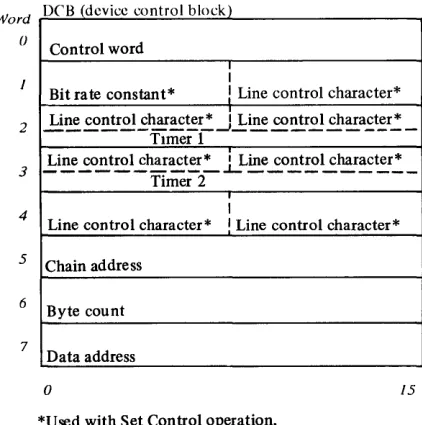
DEVICE CONTROL BLOCK (DCB)
The DeB is an eight word area in main storage which describes the specific parameters of the cycle-stealing operation. Its location in storage is assigned by the program. The DeB address transferred to the attachment via the IDeB points to word O. The address of the DeB must be even. If the DeB address is odd, the attachment sets ISB bit 1 on and terminates the cycle-steal operation with an exception interrupt. The data in the DeB is loaded and changed by the program. The DeB is fetched by the attachment, using a cycle-steal address key of zero, after successful execution of a Start command, or a Start Cycle Steal Status command. The format of the DeB for a Start Cycle Steal Status command is different from the DeB for
a Start command.
Word
()
2
3
4
5
6
7
DC'B (device control block)
Control word
I
Bit rate constant*
!
Line control character*Li~ ~ntr.£.!..£~~~r,: ~l:ine ~~r.£.! ch~a.£~r,: _ TImer 1
.!:i~ ..£o~tro1...:har~t~':"" .LLine..:.o!:t~~~r~~r,:,_
Timer 2
I
Line control character* I Line control character*
Chain address
Byte count
Data address
o 15
[image:18.613.321.534.152.350.2]*Used with Set Control operation.
Figure 2-2. Format of the DCB for a start command
6
Byte count - must be 0006 for ACC
7
Data address
o 15
Figure 2-3. Format of the DCB for a start cycle steal status command
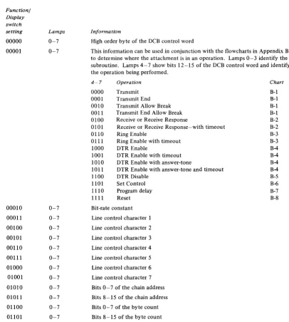
[image:18.613.68.279.506.719.2]Control Word
The control word is located in word 0 of the DeB. This
word delineates the cycle-stealing operation. The format of
the control word for a Start Cycle Steal Status command is
shown in Figure 2-3. The format of the control word for the Start command is:
Bit
o
1 2 3 4 5-7 8-9 10-15 Bito
1 2 3-4 5-7 8-9 10-15 Meaning Chaining flagNot used-must be zero Input flag
Not used-must be zero Not used-must be zero Cycle steal address key Not used-must be zero Operation 101112131415
x
X X X 0 0 X X X X X X X X X X XX 0 X 0 X 0 X 0 X 0 X 0 X 0 X 0 X 0 X 0 X 1
X X X X 0 X X
o
o
o
o
1 1o
o
o
o
0 0 1 1 0 0 0 0 1 1 0 0 1 0 0 0 Description0 Transmit Transmit end 0 Transmit allow break
1 Transmit end allow break 0 Receive
1 Receive with timeout 0 Receive response
1 Receive response with timeout 0 Ring enable
1 Ring enable with timeout 0 DTR enable
1 DTR enable with timeout 0 DTR enable wi th tone
1 DTR enable with tone and timeout 0 DTR disable
Set control PTTC
1 Set control 8-bit interchange 0 Program delay
1 Reset
Chaining flag-If this bit is on, the attachment fetches the next DCB in the chain, after completing the current DCB operation.
Not used-must be zero.
Input flag-This bit indicates the direction of data transfer. If bit 2 is on, data is transferred from the attachment to the processor. If bit 2 is off, data is transferred from the processor to the attachment. This bit must be on for either a receive operation or a Start Cycle Steal Status command.
Not used-must be zero.
Cycle-steal address key-This is a three bit key to be presented by the attachment during data transfers.
It is used by the processor to determine if the attachment is to be allowed access to certain areas of storage.
Not used-must be zero.
The attachment decodes these bits to determine the operation to be performed.
Operations
The following paragraphs describe the operations specified
by bits 10-15 of DeB word 0 (the control word).
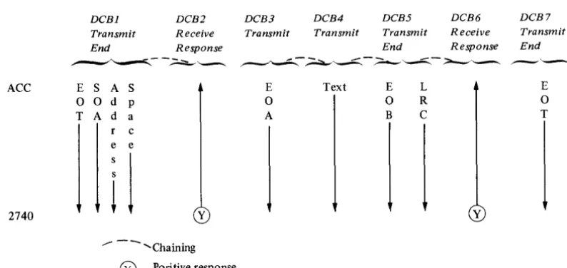
Flowcharts for the operations are shown in Appendix B. Transmit. This operation is used when another transmit type of operation is to follow immediately. Figure 2-4 shows an example of the use of this operation.
The attachment begins this operation by sending a 'request to send' to the modem and starting timer 2. The attachment then waits for a 'clear to send' from the modem. When the attachment gets 'clear to send', it resets timer 2, starts timer 1, and waits for timer 1 to timeout. When timer 1 times-out, the attachment begins fetching data from storage and transmitting the data to the remote station. The delay provided by timer 1, in this case, is called "pre-transmit delay"; its purpose is to allow the receiving station enough time to set up to receive data, and to allow time for the modem and communication lines to stabilize. If the attachment doesn't receive the 'clear to send' from the modem before timer 2 times-out, an exception interrupt occurs.
The attachment presents a device end interrupt or begins
a DeB command chaining operation when the byte count
goes to zero. The attachment stays in transmit mode and leaves its 'request to send' active at the end of this operation. This allows continuity from one transmit type of operation to another, without sending another 'request to send' and waiting for 'clear to send'.
When chaining a series of transmit type of operations, timer 2 is used only in the first operation; timer 1 provides the pre-transmit delay in the first operation only.
Pre-transmit delay First operation (transmit) Second operation (transmit) [
:
Note. Timer 1 should be set for a pre-transmit delay of approximately six milliseconds when the receiving station is a program controlled device and is directly connected or connected through a full-duplex modem.
t
f
-c
(
c
Transmit End. This operation is used to transmit the last block of data in a chain of transmit type of operations or when only one block is being transmitted. Figure 2-4 shows an example of the use of this operation.
This operation is the same as the Transmit
operation-except that the attachment exits transmit mode and starts Timer 1 after the last character is sent to the modem. When timer 1 times-out, the attachment resets its
'request to send' (if RTS is not permanently jumpered
"on"). This delay allows the last character to leave the modem before the attachment resets its 'request to send'. The timer 1 delay at the end of this operation is called "post-transmit delay." Note that timer 1 is used twice in this operation (pre-transmit and post-transmit delays), if this operation is not part of two or more transmit type of operations.
Pre-transmit delay Post-transmit delay
Transmission
---~---
Single operation (Transmit end)Post-transmit delay
~;~_is_s_w_n
____~
_____T_ra_n~;~m_is_s_w_n
____~
____ - J~~--
..
~~~----~~---~---
..
---Previous operation (transmit)
Last operation (Transmit end)
Transmit Allow Break. This operation is the same as the
Transmit operation, except that it allows the receiving station to stop the transmission. To do this, the receiving station "breaks" the line for at least 150 milliseconds. If the attachment detects this condition, it resets transmit mode and 'request to send', and presents an exception interrupt with bit 0 on in the Interrupt Status Byte. The attachment does not reset RTS if it is permanently jumpered "on."
Transmit End Allow Break. This operation is the same as the Transmit End operation, except that this operation allows the receiving station to stop the transmission in the
same way as the Transmit Allow Break operation.
Receive. This operation allows the attachment to begin placing data into storage when the attachment begins
receiving valid data. If the carrier detect jumper is installed,
'carrier detect' must be active before the attachment can begin transferring data to storage.
If while receiving, ine aitacnment detects a bad character,
it places hex 00 into storage instead of the bad character. If
the indicator panel is connected to the attachment and the switches on the panel are set to 11110, the attachment places the bad character into storage "as is."
The attachment checks every character it receives to see if the character is a COD character. The attachment presents a device end interrupt or begins a DCB command chaining operation when it recognizes a COD character.
The attachment terminates the operation and presents an exception interrupt if any of the following conditions occur:
1. The attachment is in transmit mode when this
operation is started.
2. The 'data set ready' line is off when this operation is started.
3. The attachment detects an LRC error.
4. The attachment receives an EOB and a bad character was received during this operation.
S. The attachment detects a "long" or "short" record. This error is called "incorrect length record." Refer to INTERRUPT STATUS BYTE, bit 2.
Receive with Timeout. This operation is the same as the
Receive operation, except that the attachment uses timer 1
to limit the time it will wait for the first character. It also
limits the time between characters. Failure to receive a character within this time results in an exception interrupt with bit 0 set on in the ISB. If the carrier detect jumper is installed, the attachment allows the time specified by timer 1 for 'carrier detect' to become active. If 'carrier detect' does not become active within the specified time, the attachment presents an exception interrupt and posts
"modem interface error" in cycle steal status word one.
Receive Response. This operation is used with record checking to receive the positive or negative response to a transmit operation.
This operation is the same as the Receive operation
except that when the attachment is in a Receive Response
operation, it always recognizes the COD 1 and COD 2 characters. Figure 2-4 shows an example of the use of this operation.
Receive Response with Timeout. This operation is the same
as the Receive Response operation, except that the
attachment uses timer 1 to limit the time that the attachment waits to receive the response.
Ring Enable. This operation is used in switched-line applications. It allows the attachment to recognize the fact that it is being called by another station. This command is only good for one call. The attachment cannot accept other operations until either a call is received or the device is reset. When the attachment detects a "ring," it prcscnts a device end interrupt or begins a DeB command chaining operation.
Ring Enable with Timeout. This operation is the same as the Ring Enable operation except' that the attachment uses timer 2 to limit the time it will wait for a "ring." If timer 2 times-out, the attachment presents an exception interrupt with ISB bit 0 set on.
DTR Enable. This operation causes the attachment to activate the 'data terminal ready' line. 'Data terminal ready' (DTR) must be active for any communication to take place. When the attachment receives 'data set ready' (DSR) from the modem, it presents a device end interrupt or begins a DeB command chaining operation. The attachment also presents an interrupt or begins a DCB command chaining operation if 'DSR' is already active.
Note. 'DTR' is normally jumpered on for leased lines.
ACC E
0
T
2740
DCB1
Transmit End
S A S
0 d p A d a r c
e e
i
1
DCB2 DCB3
Receive Transmit
Response
E
0
A
y
--- - - ... Chaining
®
Positive responseDTR Enable with Timeout. This operation is the same as the DTR Enable operation except that the attachment uses timer 2 to limit the time that it will wait for 'DSR' to be returned from the modem. If timer 2 times-out before 'DSR' becomes active, the attachment presents an exception interrupt and sets ISB bit 0 on.
DTR Enable with Answertone. This operation is the same
as the DTR Enable operation, except that the attachment
places an answertone on the transmit line when 'data set ready' becomes active. The duration of the answertone is determined by timer 1. The attachment presents a device end interrupt or begins a DeB command chaining operation when the timer 1 timeout occurs. This operation can be used to generate a break condition. Timer 1 should be set for approximately three seconds for this operation. The exact setting depends on the modem being used. Therefore, you should consult the manual for the modem to determine the proper length of the answertone.
DTR Enable with Answertone and Timeout. This operation
combines the functions of the DTR Enable with
Answertone and DTR Enable with Timeout operations. DTR Disable. This operation causes the attachment to deactivate the 'data terminal ready' line to the modem. The modem then disconnects itself from a switched network. TIle attachment starts timer 2 at the same time that it
deactivates 'DTR'. When the timeout occurs, the
attachment presents a device end interrupt or begins a DeB
command chaining operation. It is recommended that timer
2 be set for at least one second. This operation should not be used in a leased line application.
DCB4
Transmit
Text
DCB5
Transmit End
E L
0 R B C
DCB6 DCB7
Receive Transmit
Response End
y
E
o
[image:21.617.89.486.504.692.2]T
Figure 2-4. An example of using ACC operations
(
c
Set Control PTTC. This operation performs three
functions:
1. lt places the attachment in PTTe mode.
2. It loads the bit rate constant from word 1 of the DeB
into the attachment's clock register.
3. It loads the line control characters from the DeB into
registers in the attachment for use in transmit and receive operations. This enables the program to specify the bit pattern of all the line control characters. See the topic "Line Control" in this chapter for the location of the line control characters in the DeB.
The attachment presents a device end interrupt or begins a DeB command chaining operation at the end of this operation. The control information in the attachment
remains unchanged until another Set Control operation is
performed, or until a power-on reset occurs.
Set Control 8 Bit Data Interchange. This operation is the
same as the Set Control PTTC operation, except that this
operation places the attachment in 8 bit Data Interchange mode.
Program Delay. This operation provides a means for the program to use timer 2. The attachment loads the value specified in DeB word 3 into timer 2 and starts the timer. When the timeout occurs the attachment presents a device end interrupt or begins a DeB command chaining operation.
DCB Command Reset. This operation resets an individually addressed device. The prepare information, the information
supplied by the Set Control operation, and 'data terminal
ready' are not reset by this operation. A device end interrupt occurs or a DeB command chaining operation begins when the reset is complete.
Bit-Rate Constant
An eight bit hexadecimal number is used to control the
bit-rate within a range.
The single-line attachment can run at speeds from 37.5 to 1,200 BPS (low range) with the low-speed jumper installed on the feature card. It can run at speeds from 300 to 9,600 BPS (high range) with the high-speed jumper installed.
Each line in a multiple-line attachment can run at speeds from 37.5 to 1,200 BPS with the low-speed jumper installed. By installing the high-speed jumper, speeds between 300 and 2,400 BPS can be obtained. In a multiple-line attachment, the low-speed and high-speed
jumpers are located on the Asynchronous Communications
4-Line Adapter feature cards. There is only one set of jumpers on each 4-line adapter card. Therefore, if the high-speed jumper is installed on a 4-line adapter card, all lines associated with that card must run at speeds between 300 and 2,400 BPS.
The bit-rate constant is supplied to the attachment by the program. The constant is taken from the high order byte of
DeB word 1 and stored in the attachment during a Set
Control operation.
The bit-rate constant for low-range operation is
determined by the following formula:
Constant
=
9600 BPS -1 Round off to nearest whole number and convert to hexadecimal.hxample: Determine the bit-rate constant for 150 BPS.
9600
--1 = 63 (decimal) = 3F (hexadecimal)
150
Therefore, the hex constant supplied by the program in
conjunction with the Set Control operation would be 3F.
The bit-rate constant for high-range operation is determined by the following formula:
C onstant = 76800 BPS -1 R oun d 0 ff to t e nearest whole number h
and convert to hexadecimal.
Example: Determine the bit-rate constant for 1,200 BPS (with high-speed jumper installed).
76800
1200 --1
=
63 (decimal)=
3F (hexadecimal)Therefore, the hex constant supplied by the program in
conjunction with the Set Control operation would be 3F.
Note. It is recommended that the high-speed jumper be installed when operating at speeds over 300 BPS.
There are some bit rates in the ranges shown above that are incompatible with the attachment. The difference between the bit rate of the attachment and the bit rate of the attached terminal must not exceed 1.5 percent. To determine the difference (in percent) use one of the
following methods. An example follows method 2.
Method 1 For attachments that have the low-speed
jumper installed.
Step 1. Divide the terminal's bit rate into 9,600 and round the answer to the nearest whole number.
Step 2. Multiply the above
.000104166. This
attachment's bit-time.
answer by
gives the
Step 3. Determine the terminal's bit-time by taking the reciprocal of the terminal's bit-rate.
Method 2
Step 4. Divide the smaller of the bit-times by the larger of the bit-times.
Subtract the answer from 1.
Multiply this answer by 100. This
gives the percentage of difference between the bit-rate of the terminal and the actual bit-rate of the attachment for a given constant. For attachments that have the high-speed jumper installed. Compute the difference in the same manner as rpethod 1, making the following substitutions:
Step 1. Substitute the number 76,800 for
9,600.
Step 2. Sub s tit ute the n u m b e r
.0000130208 for .000104166.
Example: Determine the difference between the bit-rate of the attachment and the bit-rate of a terminal that operates at 134.5 BPS.
Step 1 9600
134.5
=
71.37=
71 Step 2 .000104166Step 3
Step 4
X 71
.007395786 = attachment's bit-time
134~5
= .007434944 = terminal's bit-time.007395786
(1 - .007434944) 100 = 0.53%
Therefore, a terminal with a bit rate of 134.5 bps is compatible with the attachment.
Line Control Characters
When performing a Set Control operation, DCB words 2, 3
and 4, and the low order byte of word 1 contain characters (assigned by the program) to be used as line control characters.
The usage of these characters depends on whether Eight Bit Data Interchange Code or PTTC code is being used. Refer to the topic "Line Control" for further explanation.
Note. DCB words 2 and 3 are used for timer information in
all DCBs except the DCB for a Set Control operation.
Timer 1
DCB word 2 contains the value to which timer 1 is to be set. Refer to 'Timeouts' earlier in this chapter.
Timer 2
DCB word 3 contains the value to which timer 2 is to be set.
Chain Address
This word (DCB word 5) contains the storage address of the next DCB when chaining is indicated. The address of the
chain-to DCB must be even. If it is odd, the attachment sets
ISB bit 3 on and terminates the operation.
Byte Count
The byte count is a 16 bit word (DCB word 6) which
contains an unsigned integer representing the count for this data transfer. The count is always specified in bytes.
Data Address
This word (DCB word 7) contains the storage address of the first data transfer for the operation being performed.
INTERRUPT STATUS BYTE (lSB)
When the attachment presents an interrupt to the processor, the ISB is used to record status that cannot be indicated to the program via condition codes. The
attachment presents the ISB to the processor as bits 0-7 of
the interrupt ID word. The ISB is presented only when interrupt condition code 2 is reported. Its format is:
Bit
o
1
2 3
4
5 6
7
Name
Device dependent status available Delayed command reject Incorrect length record DCB specification check Storage data check Invalid storage address Protect check Interface data check
The bits and their meanings are:
Bit Meaning
o
Device dependent status available-If this bit is on, additional status is available via the Start Cycle Steal Status command (a discussion of this status follows inthis chapter). This bit may be set on in conjunction with bit 2 (incorrect length record).
2
Delayed command reject-This bit is set on under any of the following conditions:
a. The IDCB contains an odd numbered DCB address. b. The IDCB contains an invalid function/modifier. Incorrect length record-This bit is reported only during receive operations. If ISB bit 0 is off and bit 2 is on, it indicates that the byte count has gone to zero and the attachment has not received a change of direction (COD) character. If ISB bits 0 and 2 are both on, the attachment received a COD character and the byte count was not zero.
t
\
(
'---(
c
3 4 5 6 7DCB specification check-This bit is set on under any of the following conditions:
a. The DCB contains an odd numbered chaining address (DCB word 5).
b. The byte count (DCB word 6) contains a value other than 6 for a Start Cycle Steal Status
command.
c. The data address (DCB word 7) contains an odd address for a Start Cycle Steal Status command. d. The byte count for a transmit or receive operation
is zero.
e. Bit 2 of the DCB control word (word 0) is not set appropriately for the operation.
Storage data check-This bit is set on during cycle-steal output operations only. It indicates that the storage location accessed during the current output cycle contained bad parity. The parity in main storage is not corrected. The attachment terminates the operation.
Invalid storage address-This bit is set if the storage address presented by the attachment for data or DCB access exceeds the storage size of the system. The attachment terminates the operation.
Protect check-The attachment attempted to access a storage location without the correct cycle-steal address key.
Interface data check-A parity error was detected on an interface cycle-steal data transfer. The condition may be detected by the processor I/O channel or the attachment. In either case, the operation is terminated and an exception interrupt is presented to the processor.
CYCLE STEAL STATUS WORDS
Three words of status information are available via the Start
Cycle Steal Status command. This information is available regardless of the setting of ISB bit O.
The format of the DeB for this command is shown in
Figure 2-3. Three words (6 bytes) of status information are transferred into main storage starting at the data address
contained in DeB word 7.
Word Zero
Word zero contains the main storage address of the last attempted cycle steal transfer. This residual address may be
either a data or DeB address. The value of the residual
address must be examined to determine if it is a data
address or a DeB address. When reporting a DeB address,
the attachment reports the address of the low order byte of
the last DeB word that the attachment attempted to fetch.
Word One
Word one has the following format:
Bit
o
1 2 3 4 5 6 Name Overrun Timeout Block check error DCB reject EOB, count not zero VRC errorBreak detected 7 Stop-bit error 8 Not used
9 Modem interface error 10-15 Not used
The bits and their meanings are:
Bit
o
2 3 4 Mean inKOverrun-During a receive operation, overrun occurs if the attachment is not able to transfer data to storage before the storage data register is needed for new data. During a transmit operation, overrun occurs if the attachment is unable to fetch new data from storage in time to keep a steady stream of data going out on the line.
Timeout- This bit is set on if:
a. DSR is not received from the modem within the predetermined time after an Enable with Timer
operation begins.
b. During a Receive with Timeout or a Receive Response with Timeout operation, no data is received within the limits established by timer 1. c. During a RinK Enable with Timeout operation,
'Ring indicator' is not received from the modem within the limits of timer 2.
Block check error-The LRC character received does not compare with the LRC character accumulated by the attachment. PTTC mode only.
DeB reje