IJEDR1604005
International Journal of Engineering Development and Research (www.ijedr.org)23
1New Horizon College of Engineering, Bangalore - 560103, India________________________________________________________________________________________________________
Abstract - Wheels are the most ancient discovery for humankind. The wheels on the automobiles are the different sizes and shapes that we can see around us. In the present competitive world, the disc wheel intended for normal use on passenger cars and agricultural vehicles used for agriculture and transportation of the components plays a major role in safety and at the same time they also have role to play in the costly replacements of the disc wheels. The disc wheels experience the fatigue loads due to suspension systems, the road conditions, the way of driving, the air pressure in wheel of the transporting vehicle and many more. Disc wheels also experiences static loads when the vehicles are in steady condition. The study focuses on considering all the loads under a roof to estimate the safe life of the disc wheel. The scope of the study lies in predicting the safe life of the disc wheels and suggesting the optimized disc wheel model in order to increase the life of the disc wheel to avoid costly replacements using FEA.
Index Terms - FEA, Fatigue test, Wheel disc, Static load, Safe life
________________________________________________________________________________________________________
I.INTRODUCTION
Wheels have made it easier for all of us to travel. The creation of wheels is perhaps the significant discovery. It is unbelievable to visualize the globe with no wheels around. As soon as the wheel was invented, there was a revolt in the manufacturing industry. There are different size and shapes of wheels we can see around, disc wheel intended for normal use on passenger cars and agricultural vehicles used for agriculture and transportation of the components plays a major role in safety and at the same time they also have role to play in the costly replacements of the disc wheels. The disc wheels experience the fatigue loads due to suspension systems, the road conditions, the way of driving, the air pressure in wheel of the transporting vehicle and many more. Disc wheels also experiences static loads when the vehicles are in steady condition. The study focuses on considering all the loads under a roof to estimate the safe life of the disc.
II.WHY FEA BASED FATIGUE DESIGN
Fatigue is a phenomenon where in the failure takes in three main steps called as crack initiation, propagation and rupture. Usually the materials like aluminum, steel are more used in most of the applications. These materials are crystalline in nature and the initiation of crack will take place due to formation of slips. The fatigue is highly dependent on the locations and dynamics of the component, therefore time history of stress and strain at the exact location is an essential parameter in fatigue analysis. At this point of time, is the use of FEA highly needed. using FEA we can concentrate the regions of crack, crack tip and mesh those regions to get the nearly accurate results.
III.METHODOLOGY
The fatigue life of wheel disc has been estimated with the help of CAD and CAE tools which are highly efficient and near to accuracy, literature review was carried out to understand about the methodologies to tackle the problem the industry is facing in real time. The literature review has given enough knowledge on how to deal with the linear static analysis, Modal analysis and Fatigue analysis. CAD model of the wheel disc was modeled in Solid works 2014 according to the dimensions, solid works was imported in Hyper mesh an FEA preprocessing software. Linear static analysis was carried out in Ansys and hand calculations were carried out to validate the software Ansys The fatigue life estimation was carried out in NCODE software where in rst files generated by Ansys was an input. The S-N approach to validate the life estimated by NCODE. The life calculated from the line with the NCODE software.
IJEDR1604005
International Journal of Engineering Development and Research (www.ijedr.org)24
Figure 1: Work Process3.1Meshing Checks for Quality and connectivity
Before proceeding to applying loads and boundary conditions, it is always necessary to check the model for quality and connectivity. If the model does not have proper connectivity (free edges), the analysis is not possible. Also the quality of the mesh plays a major role in analysis. few factors like warpage, aspect ratio, Jacobean if they are not under the acceptable limits, errors may take place in analysis. Ratio of the longest edge of an element to its shortest edge. Aspect ratio should be less than 5:1 in most cases, The Jacobian value ranges from 0.0 to 1.0, where 1.0 represents a perfectly shaped element. However, Jacobian values of 0.7 and above is generally acceptable. warp angle is out of plane angle. The amount by which an element or element face (in the case of solid elements) deviates from being planar. War page of up to 5 is generally acceptable. Ideal value is 0.
IV.RESULT AND DISCUSSION
4.1 Meshed Model details
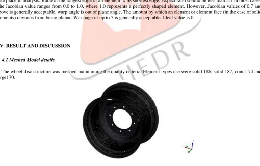
The wheel disc structure was meshed maintaining the quality criteria. Element types use were solid 186, solid 187, conta174 and targe170.
Figure 2: Meshed model of wheel disc
IJEDR1604005
International Journal of Engineering Development and Research (www.ijedr.org)25
Figure 3: Meshed model of disc Figure 4: Meshed model of rim lug
From the figures 3 and 4 shows the separate meshing parts of the disc and the rim lug, solid meshing is taken place. Solid 187 elements are used for the disc because solid 187 element has a quadratic displacement and higher 3D 10-node element. Also conta 174 and targe 170 elements is used for the rim lug, these elements represent contact and sliding between the target surface.
4.2 Load on the wheel disc
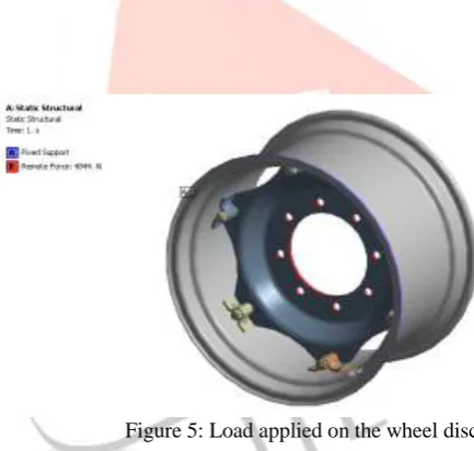
Figure 5: Load applied on the wheel disc
By seeing the above figure, the remote forces are acting on the wheel disc, by selecting the remote forces the load is acting on the center of the wheel disc this is the reason to choose the remote forces to get the more accurate results on the wheel disc, because of the rotational moment remote forces are choose, hence the load acting on the wheel is at the center. In the figure 5 the red region on the wheel disc is the remote forces acting on the wheel disc.
4.3 Linear static analysis of wheel disc
Steps to perform linear static analysis is described below. Import the Hypermesh model prepared into ansys Then apply material properties
Apply BC and the load by all degree of freedom and translate of Z direction. Then go to solution options and solve
IJEDR1604005
International Journal of Engineering Development and Research (www.ijedr.org)26
Figure 6: Von mises stress plots for the wheel discThe Maximum stress of the wheel disc is 107.57 Mpa is found at the hub bolt area also the minimum stress is 1.4073e-5 from the above figure 6, the results are in the static structural analysis from the ansys get the von mises stress results after applying the remote forces and the boundary conditions to the wheel disc. Red region occur on the wheel disc is the maximum stress on structural analysis
Figure 7: Deformation plots for wheel disc
The maximum deformation of around 0.26619mm which can be seen in the above image. Figures it can be concluded that the displacements are as less as 0.75mm which is negligible and also the stress produced is well below the yield value of steel which makes the analysis more sensible.
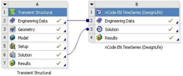
4.4 Fatigue Life calculation from N-CODE
The CODE is a plugin of Ansys which is used widely in the industries to calculate the fatigue life of product. Here also N-CODE software is used to calculate the fatigue life. The steps to perform fatigue analysis are described below
IJEDR1604005
International Journal of Engineering Development and Research (www.ijedr.org)27
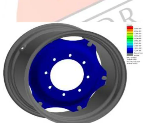
Figure 9: Life cycles plot of wheel discThe figure shows the damage of the wheel disc once the deformation done with ansys the transient analysis taken place after transient analysis done the N-code software plugin to the ansys to get the design life the wheel disc, where the N-code is widely used in the industries to calculate the life the design. From the figure 9 it shows that the life cycle of the wheel disc is 6.150e7 cycles. The damage at the point of failure also can be also seen in the below plots of damage to the wheel disc.
Since our aim is to optimize the wheel disc and estimate the safe life optimized wheel disc. The optimized wheel disc life is shown in the below figure.
Figure 10: Optimized damage plots at the failure location
IJEDR1604005
International Journal of Engineering Development and Research (www.ijedr.org)28
Figure 11: optimized life cycles plot of wheel discThe above figure 11 shows that the life cycles of the optimized wheel disc, in optimization the minimum life cycle of the wheel disc is 2.334e6 at the node of 55906, whereas in design wheel disc the minimum life cycle is 8.381e5 at the node of 55906. Hence the aim of the project is to estimate the life of the wheel disc done with the optimized wheel disc.
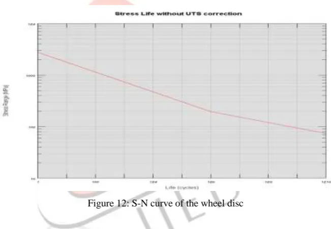
Figure 12: S-N curve of the wheel disc
From the S-N curve approach fatigue life estimation can be done, based on the material S-N curve can be obtained, since the wheel disc life estimation already estimate by using the N-code software, however the fatigue life estimation validates with the S-N curve approach. Here the fatigue life will calculate with respect to stress vs number of cycles, from the figure 12 the life cycle of the wheel disc is 2.334e6. Based on the stress in the component the fatigue life of the wheel disc is obtained. Hence the safe life of the wheel disc is estimated.
CONCLUSION
IJEDR1604005
International Journal of Engineering Development and Research (www.ijedr.org)29
[5] To Analyse the Effect of Fatigue Load Variation on Wheel Rim Vivekanand Bhanudas Bandgar, Prof. C.G. Harge[6] Analyse the Fatigue life of Aluminium Wheel Rim by using Rotary and Radial Fatigue Testing G.Arivazhagan, D.Kalaimegam, M.E. Student, 2Assistant Professor CAD CAM Engineering
[7] Computer Aided Design and Simulation of Radial Fatigue Test of Automobile Rim Using ANSYS Emmanuel M. Adigio and Ebughni O. Nangi Niger Delta University
[8] Structure Optimization of Wheel on Fatigue Failure Linghu Kezhi, Xiao Baoliang, Lin Ziyuan, Ning Yuncheng, Wang Fengqin, Li Shaobo, Huang Xueqi Research Institute of Technology of Shougang Group,Beijing,China
[9] CAD Modelling and FEA Analysis of Wheel Rim for Weight Reduction by Rahul K. Jape, Assistant Professor Departments of Mechanical Engineering VJTI, Maharashtra, India