Integer Performance Evaluation
of the Dynamically Trace
Scheduled VLIW Architecture
Alberto Ferreira de Souza
Thesis submitted in partial fulfilment o f the requirements for the degree of
Doctor of Philosophy
o f the
University of London
Department of Computer Science University College London
University of London
ProQuest Number: 10797652
All rights reserved
INFORMATION TO ALL USERS
The qu ality of this repro d u ctio n is d e p e n d e n t upon the q u ality of the copy subm itted.
In the unlikely e v e n t that the a u th o r did not send a c o m p le te m anuscript and there are missing pages, these will be note d . Also, if m aterial had to be rem oved,
a n o te will in d ica te the deletion.
uest
ProQuest 10797652
Published by ProQuest LLC(2018). C op yrig ht of the Dissertation is held by the Author.
All rights reserved.
This work is protected against unauthorized copying under Title 17, United States C o d e M icroform Edition © ProQuest LLC.
ProQuest LLC.
789 East Eisenhower Parkway P.O. Box 1346
Abstract
Very long instruction word (VLIW) machines potentially provide the most direct way to exploit Instruction-Level Parallelism (ILP), but cannot be used to emulate current general-purpose instruction set architectures. In addition, programs scheduled for a particular implementation of a VLIW model cannot be guaranteed to be binary compatible with other implementations of the same model either with a different number of functional units or functional units with different latencies. This problem is known as the VLIW object code compatibility problem. The Dynamic Instruction Formatting (DIF) concept, however, can be used to implement machines that execute code in a VLIW fashion and that are capable of overcoming the VLIW object code compatibility problem. A DIF machine schedules instructions into blocks o f VLIW instructions while executing them on a simple engine and caches these blocks for repeated execution on a VLIW engine.
This thesis presents an architecture, named Dynamically Trace Scheduled VLIW (DTSVLIW), which follows the DIF concept. The DTSVLIW architecture was conceived independently of DEF and its implementation is significantly different from the DIF implementation suggested by the proponents of DIF. A DTSVLIW machine differs in the instruction-scheduling algorithm, register renaming mechanism, register access mechanism, and VLIW cache organisation.
To evaluate the DTSVLIW, a trace-driven simulator has been implemented and experiments using SPEC benchmark programs have been performed. The effect of various architectural parameters on the DTSVLIW integer performance has been studied and the effectiveness of the DTSVLIW instruction-scheduling algorithm has been evaluated. In addition, comparisons between the DTSVLIW performance and that o f DIF and Superscalar implementations have been made. The results show that the DTSVLIW achieves significant ILP with feasible machine configurations and that, although simpler, the DTSVLIW instruction-scheduling algorithm is as effective as the DIF’s. The results also show that the DTSVLIW performs better than the DIF and Superscalar architectures for representative machine configurations while using less hardware resources and in a way that should not produce a longer clock cycle than these architectures.
Acknowledgements
I would like to give a very special thanks to my supervisor Peter Rounce for his friendship, encouragement, attention, support, kindness, and invaluable advice throughout these three years.
I would also like to give a special thanks to Antonio Liotta. His company and friendship in all the critical moments of this research work has been invaluable.
My thanks to Jorge Ortega-Aijona, Lee Braine, Tom Quick, Artur d ’Avila Garcez (from Imperial College London), Rafael Bordini, Nadav Zin, Adil Qureshi, and all other friends of the Department of Computer Science at UCL for their encouragement, advice, and criticism.
I am indebted to Eliseu Monteiro Chaves Filho for allowing me to use the code of his Sparc scalar simulator.
I owe a huge debt o f gratitude to my colleagues of the Departamento de
Informatica at Universidade Federal do Espirito Santo (UFES) for carrying out my teaching duties while I have been here.
I gratefully acknowledge the financial support provided by the Brazilian people
through the Coordenagao de Aperfeigoamento de Pessoal de Nivel Superior
(CAPES) and UFES.
Contents
Integer Performance Evaluation of the Dynamically Trace Scheduled VLIW
Architecture...1
Chapter 1 Introduction... 14
1.1 Research Motivation... 17
1.2 Goal o f this Thesis... 17
1.3 Overview of the Contributions...18
1.4 Organisation of this Thesis...19
Chapter 2 Background... 20
2.1 Architectures for Exploiting IL P ... 21
2.1.1 Pipelined Architectures...21
2.1.2 Superscalar Architectures...22
2.1.3 Vector Architectures...25
2.1.4 VLIW Architectures... 27
2.1.5 Multithreaded Architectures...28
2.2 ISA and Hardware Support for Exploiting IL P ... 30
2.2.1 Register Renaming...31
2.2.2 Branch Prediction...32
2.2.3 Speculative Execution and Interrupt Handling...36
2.2.4 Memory Disambiguation...38
2.2.5 Predication...39
2.2.6 Instruction Hoisting...41
2.2.7 Data Dependence Collapsing...43
2.3 Compiler Support for Exploiting IL P... 43
2.3.1 Trace Scheduling...44
2.3.2 Superblock Scheduling...45
2.3.3 Percolation Scheduling...46
2.3.4 Loop-unrolling...48
2.3.5 Software Pipelining...50
2.4 ILP Available in Programs... 52
2.5 Historical Perspective of ILP Exploitation...54
2.5.1 Late 70s...54
2.5.2 Beginning o f the 80s...54
2.5.3 Late 80s...55
2.5.4 Beginning o f the 9 0 s...55
2.5.5 Late 90s...56
Chapter 3 Related W ork... 57
3.1 Related Work on Microcode Scheduling...57
3.2 Related Work on VLIW Architectures... 59
3.3.2 Hardware Approaches...67
3.4 Related Work on Exploiting Code Locality...70
3.4.1 Trace Cache...70
3.4.2 Value Prediction and Instruction Reuse...74
Chapter 4 The DTSVLIW Architecture... 76
4.1 The Scheduler Engine...78
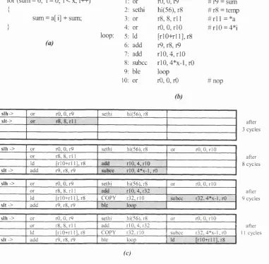
4.1.1 The Scheduling Algorithm...79
4.1.2 Copy Instructions Handling...82
4.1.3 Control-Transfer Instructions Handling...83
4.1.4 No-operation Instructions Handling...84
4.1.5 Load and Store Instructions Handling...84
4.1.6 Save and Restore Instructions Handling...84
4.1.7 Non-schedulable Instructions Handling...84
4.1.8 Multicycle instructions Handling...85
4.2 DTSVLIW Long Instruction Format...86
4.3 DTSVLIW Long Instruction Addressing... 88
4.4 The VLIW Cache...91
4.5 The VLIW Engine...92
4.6 Scheduler Unit Implementation... 93
4.7 Memory Aliasing Detection...96
4.8 Exception H andling... 97
4.9 Object Code Compatibility Issues... 98
4.10 Differences Between DTSVLIW and D IF...100
Chapter 5 Experimental Methodology...102
5.1 The DTSVLIW Simulator...102
5.2 Simulation Parameters...103
5.3 Benchmark Programs... 105
5.4 M etrics... 106
Chapter 6 Experiments... 108
6.1 Effect of Some Architectural Parameters on the DTSVLIW Performance.. 108
6.1.1 VLIW Fetch Starting Point... ...108
6.1.2 Block Size and Geometry...112
6.1.3 VLIW Cache Size...113
6.1.4 VLIW Cache Associativity...114
6.1.5 Instruction Cache S ize...114
6.1.6 Multicycle Instructions Latency...116
6.1.7 A Feasible DTSVLIW Machine Configuration...119
6.2 Effectiveness of the DTSVLIW Scheduling Algorithm... 122
6.2.1 Evaluation o f the Performance o f the DTSVLIW, Greedy, and FCFS Scheduling Algorithms — Untyped Functional Units...123
6.2.2 Evaluation o f the Performance o f the DTSVLIW, Greedy, and FCFS Scheduling Algorithms — Typed Functional Units...124
6.3 DTSVLIW versus D IF...126
6.4 DTSVLIW versus VLIW ... 130
6.5 DTSVLIW versus Superscalar... 131
Chapter 7 Discussion...134
7.2 DTSVLIW versus Explicitly Parallel Instruction Computing Architectures 138
7.3 Research Architectures for ILP Exploitation...140
7. 3. 1 IRAM Architectures...140
7.3.2 Simultaneous Multithreaded Architectures...141
7.3.3 Dataflow Architectures...141
7.3.4 Multiscalar Architectures...143
1A Critical Assessment of this Research Work...144
7.4.1 On the Limits o f Validity o f the Experimental Results...144
7.4.2 On the DTSVLIW Implementation Difficulties...147
Chapter 8 Summary, Conclusions and Future Work... 150
8.1 Thesis Summary...151
8.2 Conclusions... 152
8.3 Future W ork... 155
8.3.1 Mechanisms fo r Reducing the Impact o f Load Latency...155
8.3.2 New VLIW Cache Organisations...155
8.3.3 Next Long Instruction Prediction...156
8.3.4 Clustered DTSVLIW...156
8.3.5 DTSVLIW Performance with Other Classes o f Program...156
8.3.6 DTSVLIW-Tailored Compilers...156
Glossary... 158
List of Figures
Figure 1.1: The Dynamically Trace Scheduled VLIW (DTSVLIW) architecture 17
Figure 2.1: Pipelining... 22
Figure 2.2: Superscalar machine...25
Figure 2.3: VLIW machines... 28
Figure 2.4: Data and control dependencies... 31
Figure 3.1: Trace Cache Architecture...73
Figure 4.1: A DTSVLIW machine... 78
Figure 4.2: Scheduling algorithm running example... 82
Figure 4.3: DTSVLIW long instruction format examples... 87
Figure 4.4: VLIW Engine instruction addressing... 91
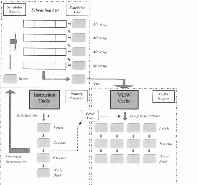
Figure 4.5: Scheduler Unit pipeline... 92
Figure 4.6: Scheduling list... 96
Figure 6.1: Variation o f parallelism with VLIW fetch starting point: 8x8-block.... 111
Figure 6.2: Variation of parallelism with VLIW fetch starting point: 16x16-block 111 Figure 6.3: Variation of parallelism with VLIW fetch starting point: 8x8-block and 16x16-block...I l l Figure 6.4: Variation of parallelism with block size and geometry... 113
Figure 6.5: Variation of the parallelism with VLIW Cache siz e... 114
Figure 6.6: Variation of parallelism with VLIW Cache associativity... 114
Figure 6.7: Variation of parallelism with different Instruction Cache configurations: 3072-Kbyte VLIW Cache...116
Figure 6.8: Variation o f parallelism with different Instruction Cache configurations: 192-Kbyte VLIW Cache...116
Figure 6.9: Variation of the parallelism with load/store instructions latency — 8x8-block...118
Figure 6.10: Variation of the parallelism with load/store instructions latency — 8x 16-block...118
Figure 6.11: Performance of a feasible DTSVLIW machine...122
Figure 6.12: Performance of the DTSVLIW, Greedy, and FCFS algorithms — untyped F.U...124
Figure 6.13: Performance of the DTSVLIW, Greedy, and FCFS algorithms — typed F.U...126
Figure 6.14: DTSVLIW versus DIF: untyped functional units...129
Figure 6.15: DTSVLIW versus DIF: typed functional units...129
Figure 6.16: DTSVLIW versus DIF: more realistic models...129
Figure 6.17: DTSVLIW versus VLIW... 131
Figure 6.18: DTSVLIW versus PowerPC620... 133
Figure 7.1: Different forms of ISA contract... 136
List of Tables
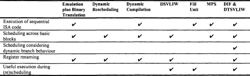
Table 3.1: Features implemented by different approaches for tackling the VLIW
object code compatibility problem ...70
Table 5.1: Fixed parameters...104
Table 5.2: Variable parameters... 104
Table 5.3: Benchmark programs and Input D ata... 106
Table 6.1: Percentage o f cycles waiting load/store latency in the Primary Processor and percentage o f VLIW execution cycles... 118
Table 6.2: Performance data of a feasible DTSVLIW m achine...122
Table 6.3: Resource consumption of a feasible DTSVLIW machine... 122
Table 6.4: Summary o f the results — 4x4 & 5x4 machine configurations...126
Table 6.5: Summary of the results — 8x8 & 10x8 machine configurations...126
Chapter 1
Introduction
In the standard model of computation, a computer program coded in machine language can be viewed as a vector in which each element is an instruction that commands a small set of simple operations. The computer starts executing the program at an instruction and proceeds executing instructions in ascending order. This order can be broken, however, by conditional or unconditional branch instructions, which can move the execution flow, forward or backward, a specified number of instructions. The program semantics is guaranteed to be correct if the instructions are executed atomically, and in the sequence specified by the program ordering and the taken branches.
A simple sequential computer processor executes each instruction completely before starting the execution of the next instruction. However, many operations are common to the execution of all instructions, which makes it possible to implement a processor in a pipelined way, as in a factory, to improve its performance (its ability to execute the program faster). In addition, sometimes instructions can be executed in parallel or even out of the order specified in the program without changing the program semantics. This can be exploited by properly designed processors containing many functional units capable of operating in parallel. Furthermore, the pipeline technique can be combined with parallel and out-of-order execution capabilities in a single processor for improving performance even further. Such processors are said to
follow the Superscalar architecture [Johnson91].
code in a parallel form. In this case, each element of the vector representing the program can hold a certain number of independent operations that can be executed in parallel. Properly designed processors execute such a program by fetching one element o f the vector at a time and by issuing the operations in parallel. Such
processors are said to follow the Very Long Instruction Word (VLIW) architecture,
because their instructions have hundreds or even thousands of bits to accommodate several operations [Fisher84]. VLIW processors can also be implemented in a pipelined fashion.
In VLIW systems, the compiler has complete responsibility for creating a package o f operations that can be simultaneously issued. VLIW processors do not dynamically make any decisions about multiple operation issue, and thus they are simple and fast. In addition, because the VLIW compiler can look for parallelism between instructions in the whole program, VLIW architectures are potentially the
most direct way of exploiting the instruction-level parallelism (ILP). However, the
assumptions built into the code by the VLIW compiler about the hardware prevent
code compatibility between different implementations o f the same VLIW instruction
set architecture (ISA). VLIW processors with different levels o f hardware parallelism require recompilation o f the source code. For instance, the code generated for a VLIW processor with four operations per VLIW instruction could not run on another VLIW processor with five operations per VLIW instruction without
recompilation. This problem, known as the VLIW object-code compatibility problem,
has limited the commercial interest in VLIW architectures [Rau93b].
Recently, a new architectural concept named Dynamic Instruction Formatting
In this thesis, we present a new architecture that follows the DIF concept. This
architecture, named Dynamically Trace Scheduled Very Long Instruction Word
(DTSVLIW) architecture [deSouza98a], has been conceived independently o f DIF, which has permitted an implementation significantly different from that suggested by the proponents of DIF. We have shown that the DTSVLIW is easier to implement than DIF and delivers equivalent performance with less hardware resources [deSouza99a].
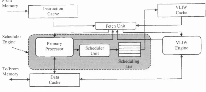
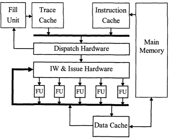
Figure 1.1 shows a block diagram of the DTSVLIW architecture. In the DTSVLIW architecture, the Scheduler Engine fetches instructions from the Instruction Cache and executes them first using a simple pipelined processor — the Primary Processor. In addition, its Scheduler Unit dynamically schedules the trace produced during this execution into VLIW instructions, placing them as blocks of VLIW instructions in the VLIW Cache. If the same code is executed again, it is then fetched by the VLIW Engine from this cache and executed in a VLIW fashion. In the DTSVLIW architecture, the Scheduler Engine provides object-code compatibility, and the VLIW Engine provides VUW performance and simplicity.
To execute code in two distinct modes, one sequential and one parallel, results in four positive characteristics:
1. Code compatibility between different machine generations is facilitated — DTSVLIW machines with different levels o f hardware parallelism can easily share the same ISA.
2. Complex instructions can be dealt with in sequential mode — During sequential execution, complex instructions can be decomposed into several simpler operations, which can later be executed in parallel mode.
3. The task o f finding parallelism is simplified — The DTSVLIW’s Scheduler Unit receives no more than one instruction per cycle and, therefore, can have a simple and fast hardware implementation.
4. Instruction exceptions can be dealt with in sequential mode — In case o f an instruction exception during parallel execution, a DTSVLIW machine can switch to sequential mode and deal with the exception in this mode.
reuse the blocks o f VLIW instructions saved in the VLIW Cache m any tim es. A
DTSVLIW m achine, then, relies on code temporal execution locality to im prove
program execution perform ance.
From
M em o ry V LIW
C a ch e Instruction
C a ch e
♦ { Fetch U nit
S c h ed u le r
E n g in e V L IW
E n g in e Prim ary
P r o cesso r
T o/F rom M em o ry
D ata C a ch e
F ig u r e 1.1: T h e D y n a m ic a lly T r a c e S c h e d u le d V L IW (D T S V L I W ) a r c h ite c tu r e
1.1
Research Motivation
The m ain m otivation for this research cam e from the observation that even small
instruction caches (16-K byte or 4098 instructions) can achieve average hit rates
higher than 99% with the SPEC92 and SPEC95 benchm ark suites [SPEC, G ee93,
C ham ey97]. This shows that there is strong temporal execution locality in program s.
The D TSV LIW exploits temporal execution locality by converting the code into
blocks o f VLIW instructions in the first execution encounter and by executing it in
the VLIW Engine in subsequent encounters. To make a m echanism like this w ork
and take advantage o f the DTSVLIW architecture characteristics, the conversion
algorithm has to be effective in producing VLIW code. In addition, it has to be
sim ple enough not to render the clock cycle tim e longer than that determ ined by the
VLIW Engine design. The results achieved with this research so far supports the
view that this can be achieved [deSouza99a, deSouza99c].
1.2 Goal o f this Thesis
The aim o f the research w ork presented in this thesis is to exam ine the follow ing
• The DTSVLIW architecture can overcome the VLIW object code compatibility problem while preserving the VLIW architecture simplicity
and high clock rate.
• The DTSVLIW can achieve higher performance than the DIF and
Superscalar architectures using equivalent hardware.
With this aim, we describe the DTSVLIW in detail and show that it can be implemented without taking the clock cycle far from that determined by a pure VLIW design. In addition, we show that the DTSVLIW can execute legacy code in VLIW mode. To better understand the DTSVLIW architecture, we investigate the effect of various architectural parameters on its performance via experiments. We then compare the DTSVLIW performance with that of DIF and Superscalar architectures.
1.3 Overview of the Contributions
The main contributions o f this research work are:
• Conception of a VLIW-based architecture — the DTSVLIW — capable of taking advantage of the code temporal locality for achieving program execution performance. The DTSVLIW uses a pipelined code-scheduling algorithm that effectively produces VLIW instructions dynamically [deSouza98a],
• Proof that the core operation of the DTSVLIW scheduling algorithm has complexity comparable to that of an integer adder and, as such, can be implemented in hardware level without impacting the DTSVLIW clock cycle time [deSouza99a].
• Evaluation o f the effect of important DTSVLIW architectural parameters on its performance [deSouza98b, deSouza99a, deSouza99b].
• Evaluation of the effectiveness of the DTSVLIW scheduling algorithm [deSouza99c].
1.4 Organisation of this Thesis
Chapter 2
Background
The ultimate goal of the computer designer is to minimise the execution time of any
given program. We can express this execution time, T, as:
T = N x C x S
where N is the number of instructions that need to be executed, C is the average
number of processor clock cycles per instruction, and S is the number of seconds per
cycle. To a first approximation, N, C, and S are affected primarily by the compiler technology, the ISA, and the implementation technology, respectively [Rau89].
An approach to reduce N at the expense of a smaller increase in C is to exploit
the parallelism available in horizontally microcoded machines [Salisbury76]. This can be done by defining complex instructions that exploit the internal micro
parallelism of these machines in the hope that N would decrease more sharply than C
would increase. This is the general idea behind Complex Instruction Set Computers
(CISC).
Microprogramming can be used to implement powerful CISC ISAs, with complex instructions capable of commanding many operations involving many operands in registers or main memory. A typical CISC instruction, for example, can read a value from memory, add this value to the content of an internal register, and store the result in another position in the memory.
T focuses on the use of very simple instructions, which would reduce C and, due to its simplicity, S as well. The resulting increase in N can be minimised by fine-tuning the compiler technology and the RISC ISA’s implementation [Patterson85].
RISC instructions usually command a single operation involving no more than one access to memory. Due to their simplicity, RISC instructions are not implemented using microprogramming. RISC machines are, therefore, equivalent to a vertical microprogrammable microarchitecture exposed to the programmer o f the ISA level.
Improvements in the implementation technology alone can also reduce T by
reducing S. However, assuming the use of the fastest technology, any further increase
in performance would require the exploitation of the parallelism available in programs.
2.1 Architectures for Exploiting ILP
Machines capable of exploiting parallelism in the ISA level realise ILP. In this section, we discuss briefly some important machine architectures for exploiting ILP.
2.1.1 Pipelined Architectures
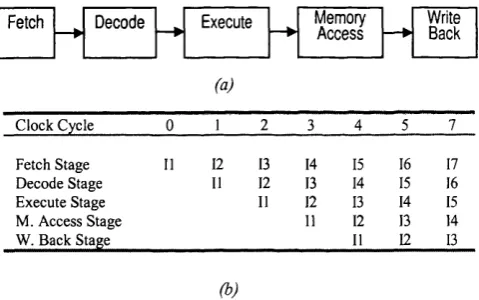
There are two basic types o f ILP: temporal and spatial. Pipelining realises temporal ILP. It refers to the segmentation of an instruction’s execution into several sub processes that are executed by dedicated autonomous units (pipe stages). Successive instructions can be executed in a mode analogous to car assembly in a factory. Using pipelining, several instructions can be executed in parallel, each one in a different pipe stage, and in a different phase of its execution (Figure 2.1). Because the operations performed by each pipe stage are simple, the pipe stages can be implemented with simple hardware, which results in a high machine-clock frequency. Theoretically, the deeper (larger number of pipe stages) the pipeline, the faster the machine is, but there are of course practical limitations to this rule. Kunkel and Smith [Kunkel86] have studied the relationship between the theoretical linear speedup that pipelining offers and its practical limitations.
Stretch [Bloch59]. After IBM Stretch, the majority of high-end machines have used some form o f pipelining. Surveys on pipelining include Keller [Keller75], Ramamoorthy and Li [Ramamoorthy77], and Kogge’s book [Kogge81], entirely devoted to pipelining.
Spatial ILP is that present in processors with multiple functional units. It refers to the execution o f more than one instruction simultaneously in different functional units o f the processor. Temporal and spatial parallelism can be present at the same time. Indeed, a few years after the IBM 7030 Stretch had been constructed, the CDC6600 was produced with pipelining and multiple functional units that can operate in parallel [Thomton70].
The arithmetic portion o f CDC6600 has 10 functional units, and many instructions can be issued to its functional units and executed in parallel. To do so,
the CDC6600 looks-ahead in the sequence of instructions originally specified in the
program in order to determine those that can be executed at the same time.
Fetch — ► Decode — ► Execute — ► Memory Write Access — ► Back
(a)
C lock C ycle 0 1 2 3 4 5 7
Fetch Stage 11 12 13 14 15 16 17
D ecod e Stage 11 12 13 14 15 16
E xecute Stage 11 12 13 14 15
M . A ccess Stage 11 12 13 14
W . B ack Stage 11 12 13
(b)
Figure 2.1: Pipelining, (a) The classic five-stage computer pipeline, (b) After filling all pipeline stages, one instruction can be completed per clock cycle. Up to five instructions, each in a different pipe stage, can be executed in parallel in this pipeline.
2.1.2 Superscalar Architectures
The term look-ahead derives from a class of schemes in which programs are
[Keller75]. The look-ahead scheme used in CDC6600 is called Thornton's algorithm and is described in [Thomton64] and [Thomton70].
The IBM 360/91 introduced a powerful look-ahead scheme named Tomasulo's algorithm [Anderson67, Tomasulo67]. A variant of Tomasulo's algorithm was used in the IBM RISC System/6000 design [Grohoski90] and, since then, various variants of Thornton and Tomasulo's algorithms have been used in many machines known as
Superscalar machines [Johnson91].
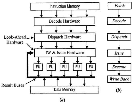
The core of a Superscalar machine, shown in Figure 2.2, is the look-ahead
hardware, also called dynamic scheduling hardware. The role o f the dynamic
scheduling hardware is to dispatch decoded instructions to the instruction window, and to select instructions from this window to issue to the functional units each clock cycle. The instruction window is central to the dynamic scheduling hardware and may be organised as a large structure with many entries or as several small structures, one for each functional unit. In the latter case, each structure has few entries and each entry is called reservation station.
During the dispatch process, dependency information is added to the instructions, their outputs are renamed (see Subsection 2.2.1), and they are stored into the instruction window. The dependency information comprises dependencies between the instructions being dispatched themselves and between these and other instructions previously dispatched, such as which instruction is going to produce a needed operand. Available input operands are also added to the instructions and saved with them into the instruction window during dispatch.
During the issue process, the issue hardware collects results from the result buses (Figure 2.2), updates the instruction window with these results, selects groups o f instructions ready to execute, and issues these groups to the functional units. The results collected from the result buses are stored into the instruction window in the entries that have instructions that were dispatched with an incomplete set o f input operands. When all input operands of an instruction are available, the issue hardware marks it as ready to execute. Groups o f ready instructions are selected by the issue hardware and issued to the functional units to execute.
compare the output o f all functional units with the inputs of all instructions in the instruction window. This requires wires to connect all functional units to all instructions in the instruction window, and a number of comparators and associated logic proportional to the number of functional units times the number of instructions in the window. Therefore, Superscalar processors with many functional units and large instruction windows have a complex issue hardware, and a complex issue hardware impacts negatively on the clock cycle time of these machines. A possible solution to this problem is to organise the Superscalar core in clusters of functional units and associated small instruction windows, and to add special buses for communicating results between these clusters [Palacharla97, Vajapeyam97].
The term superscalar was coined by Agerwala and Cocke [Agerwala87] to name machines that dispatch multiple independent instructions per clock cycle (in their original form, the Thornton and Tomasulo’s algorithms can dispatch one instruction per cycle only). In fact, Agerwala and Cocke proposed this approach as an extension of the RISC ideas [Hennessy86]. A machine that follows the RISC philosophy has a fixed instruction length, load-store instruction set (all instructions operate on registers and two specific instmctions operate with memory: load and store), limited addressing modes, and a small number of possible operations. These characteristics result in easier pipelined and superscalar implementation. Nevertheless, CISC IS As can also be interpreted by machines that follow the Superscalar architecture such as, for example, the Intel Pentium [Saini93] and the Intel Pentium Pro [Bhandarkar97] processors with the Intel IA-32 ISA. The Intel Pentium, less powerful than the Intel Pentium Pro, can dispatch up to two simple instructions (RISC-like instructions present in the IA-32 ISA repertoire) to two parallel execution pipelines of the machine. The Intel Pentium Pro, on the other hand, has three parallel decoders that convert up to three IA-32 ISA instmctions per clock cycle into multiple RISC-like micro-operations which can be dispatched to reservation stations of five different functional units.
However, the compiler can be given the primary responsibility for finding the parallelism and, in addition, for expressing it in the form of parallel code. From the different forms of parallel code that can be produced, two have been particularly
successful: Vector code and VLIW code.
Look-Ahead Hardware
Result Buses
Execute
Write Back Issue Dispatch
D ecode Fetch
Data Memory
IW & Issue Hardware Dispatch Hardware
Instruction Memory
Decode Hardware
(«)
Figure 2.2: Superscalar machine. IW stands for instruction window and FU for functional unit. (a) A simple Superscalar data path. (b) A simple Superscalar pipeline.
2.1.3 Vector Architectures
To produce Vector code, the compiler looks for loops in the program and, by using vectorization techniques [Padua86], generates vector instructions that implement, or partially implement, the loops. The Vector code produced is executed by Vector machines. These machines have specialised vector functional units that compute individual element operations of a vector operation in parallel [Patterson96 (Appendix B)].
writing the result into the output vector register repeatedly, from the first until the last vector element of each vector register. These operations are executed sequentially; however, in a very deep pipelined functional unit. Some Vector processors do not have vector registers and operate directly with memory.
A vector functional unit can be implemented with a very deep and fast pipeline because each result is independent of the previous in a vector operation. This independence is decided at compile time, when the vector instruction is selected to perform a sequence o f operations. Because the parallelism is decided at compile time, Vector processors do not need the complex look-ahead hardware of Superscalars.
Vector operations can execute in parallel in different functional units if they are independent. Using chaining, a technique that allows a vector operation to start as soon as the individual elements of its vector source operand become available, even some dependent operations can execute in parallel [Ramamoorthy77, Patterson96 (page B-24)]. Scalar and vector operations can also be executed in parallel if they do not write into each other’s inputs. Nevertheless, in these cases, look-ahead hardware is required.
Many Vector machines became successful commercially; however, by the end of the 1980s their importance started fading. This was caused by improvements in Superscalar architectures, their compilers, and their implementation techniques. At the beginning of the 1990s, these improvements made Superscalar machines, which were more than 10 times cheaper than contemporary Vector machines, faster than
Vector machines in the execution of the very important class of scalar programs
[Patterson96 (page B-38)]. Scalar programs are characterised by a lack of long loops that can be vectorized. Compilers, database manipulation programs, and system utilities are examples of scalar code. Nowadays, Vector computers are demanded only by specialised users that require vector performance.
2.1.4 VLIW Architectures
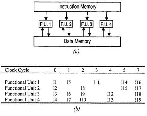
The other successful form o f parallel code that can be produced by compilers, VLIW code, is executed by VLIW machines [Fisher84]. VLIW machines can execute
several scalar operations in a single clock cycle. They have long instructions
F.U.2 F.U.3 F.U.4
Data Memory Instruction Memory
(a)
C lo ck C ycle 0 1 2 3 4 5 7
Functional U nit 1 11 15 111 114 116
Functional U nit 2 12 18 115 117
Functional U nit 3 13 16 19 112 118
F u nctional U nit 4 14 17 110 113 119
(b)
Figure 2.3: VLIW machines, (a) A hypothetical VLIW machine, (b) The compiler can put up to four instructions into each long instruction of this VLIW machine. If one instruction slot cannot be filled, a no-operation (nop) instruction is used.
2.1.5 Multithreaded Architectures
Like pipelining, multithreading realises temporal parallelism, but in a different way. A Multithreaded architecture can execute many threads (processes from different programs or the same program) in parallel with the same hardware. To do so, a multithreaded processor has multiple sets of storage positions for recording the state (also called context) of different threads. The multithreaded processor executes one or more instructions o f one thread and then switches to another thread ready for execution, repeating this process continuously in a round robin or prioritised way. Thread switching can be triggered either by the clock or by dynamic events such as cache misses. By using multithreading, the utilisation of the processor hardware is increased because latencies due to cache misses, inter-instruction dependencies, etc, can be hidden by the execution of other threads.
of clock cycles. In multithreading, the processor has storage space for several threads and its hardware is typically able to switch between threads in one clock cycle. Nevertheless, Multithreading can be used to implement multiprogramming.
To my knowledge, multithreading was first employed in the peripheral subsystem of the CDC6600 [Thomton70], in which a single processor is connected to 10 independent ferrite-magnetic-core memories and 10 independent register files. On each clock cycle, the processor is connected to one particular register file and one associated memory. The processor executes one instruction in this clock cycle and switches to the subsequent register file-memory pair on a circular basis. Because the CDC6600’s peripheral processor hardware is 10 times faster than its ferrite- magnetic-core memories, it is able to perform as if it were 10 processors instead o f one, by sharing its hardware between 10 different programs. When 10 I/O programs are running simultaneously, the Multithreaded architecture of the CDC6600’s peripheral processor hides the memory latency completely, making the most o f the available hardware.
The basic architectural principle behind multithreading — sharing hardware resources between threads — can be associated with other parallel processing paradigms. Some researchers have proposed, for example, multithreaded
multiprocessors [Smith_BJ81], while others have proposed multithreaded
multiprocessors where the processors are VLIW machines [Alverson90]. Tullsen and his colleagues have proposed an advanced Superscalar architecture capable o f issuing several instructions from different threads to the machine’s functional units in the same clock cycle [Tullsen95]. They called the technique embodied in this
architecture simultaneous multithreading. In Sohi’s Multiscalar architecture
[Sohi95], fme-grain tasks from a single program are defined automatically at compile time, as opposed to threads defined in the source code by the programmer or threads o f different programs. These tasks are dynamically assigned to different execution contexts o f the Multiscalar processor.
multithreading advantage. Nevertheless, as the gap between processor and main memory speed increases, multithreading may become more important due to its latency-hiding ability.
2.2 ISA and Hardware Support for Exploiting ILP
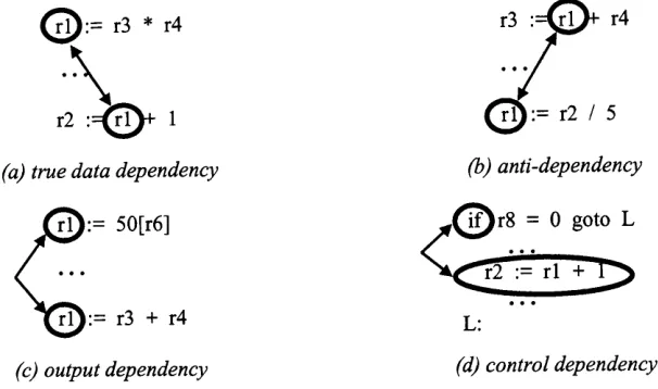
Pipelined, Superscalar, Vector, and VLIW architectures exploit the ILP available in programs. The amount of ILP that can be exploited is limited by data and control dependencies between instructions (Figure 2.4). These dependencies impede:
• execution of consecutive instructions in pipelined architectures
• parallel instruction issue in Superscalar architectures • loop vectorization in Vector architectures
• placement of more instructions into the long instructions of VLIW architectures by VLIW compilers
All this leads to poor utilisation of the available hardware — while one hardware unit is busy others may be idle, waiting for the results from the busy unit.
The ISA itself can give support to overcome dependencies by allowing direct expression o f ILP, as in Vector and VLIW ISAs. However, there are other forms of ISA support for exploiting ILP, such as bits in the instructions encoding to help
branch prediction or to express predication. Hardware can support ILP exploitation
with, for example, register renaming or dynamic branch prediction. In the rest of this
(a) true data dependency (b) anti-dependency
r l j : = 50[r6] r^ ^ r 8 = 0 g o to L
r2 := r l +
r l j : = r3 + r4 L:
(c) o u tp u t d e p e n d e n c y (d) c o n tr o l d e p e n d e n c y
Figure 2.4: Data and control dependencies, (a) Two instructions have a true data dependency if the result of the first is an operand of the second, (b) Two instructions have an anti-dependency if the first uses the old value in some location and the second sets that location to a new value, (c) Two instructions have an output dependency if they both assign a value to the same location, (d) There is a control dependency between a branch and an instruction whose execution is conditional on it.
2.2.1 Register Renaming
Anti-dependencies and output dependencies (Figure 2.4) can be eliminated by
renaming. They are called name dependencies because, as opposed to true data
dependencies, there is no value being transmitted between the instructions. In anti dependencies and output dependencies, it is the use of a name that causes the dependency, not the need for a previously computed value. For example, in Figure 2.4b, if the result of the second operation, “r2 / 5”, is written into another register, say “r5”, the anti-dependency disappears and the two statements can then be executed either in parallel or in reverse order. The same is true for Figure 2.4c if we change ‘W ” to “r2” in the second statement, for example. The names used for renaming cannot be in use at the point of renaming; that is, the names used cannot specify valid values that might be needed for subsequent instructions.
dynamically. In fact, the main difference between the Thornton and Tomasulo’s dynamic scheduling algorithms is the ability to perform renaming - the Thornton’s algorithm does not support renaming [Patterson96 (pages 240-261)].
2.2.2 Branch Prediction
Branch prediction [Lee_JFK84, Fisher92, Pan92, McFarling93, Nair95] can reduce the impact o f control dependencies (Figure 2.4d) on machine performance. Control dependencies impact on performance because instmctions that depend on a conditional branch can only be executed after the branch outcome is known. For example, if in Figure 2.1 (page 22) the instruction 15 is a conditional branch that targets instruction 132 at that point of program execution, the processor fetches and decodes instruction 16 in vain and fetches 17 in vain. This happens because the
processor only leams the branch outcome when 15 is in the execute pipeline-stage.
Branches can be predicted statically by the compiler or dynamically by the hardware. They can be predicted at compile time using knowledge about the program itself. A conditional branch at the end of a loop that is used to branch back to the beginning for another loop interaction may be predicted as taken, for example. Another alternative for branch prediction at compile time is profiling [Fisher92]. In this case, a version o f the program is executed one or more times with typical inputs and the branches’ behaviour is saved. The branch behaviour information is then used to statically predict the program branches as taken or not taken in an eventual program recompilation. Whether or not profiling is used, the compiler establishes its prediction by setting a taken-bit in the branch instruction to inform the hardware whether the branch is predicted as taken or not taken. Therefore, compiler oriented static branch prediction has to be supported by the ISA.
Usually, the hardware checks the taken-bit and moves the control-flow to the appropriate branch-target instruction when the branch instruction leaves the decode stage of the processor’s pipeline. In the example mentioned above, if 15 has a taken- bit and it is set at true, the processor can redirect the fetch under the control o f 15
when it is in the decode pipeline-stage. In such case, 16 is still fetched but not 17; 132
on average for the integer programs of the SPEC89 benchmark suite [Patterson96
(page 176)].
Certain ISAs go beyond the static branch prediction mechanism described and use the concept of delayed branches to try to avoid the useless fetch o f 16 in the last example. In such ISAs, one or more instructions that follow a branch (usually just one) are unconditionally executed. These instructions are said to be in the branch delay slots. The compiler can use branch delay slots to accommodate useful
instructions. An even more elaborate scheme adds an extra annul-bit to the branches
encoding to say whether the instruction in the branch slot should be annulled when the branch is not taken. Using these facilities, the compiler could put 132 after the 15
branch in the example above, and set the annul-bit and the taken-bit o f 15 at true. This would favour a possibly more frequent case when 15 is taken — no processor
cycles would be lost in such case, provided that the 15 target can be computed in the
decode pipeline-stage. The Sparc Version 9 ISA [Patterson96 (page C-25)], for example, incorporates the annul-bit and the taken-bit in some o f its conditional branches. Experiments have shown that the compiler is able to fill 79% of branch delayed slots and that delayed slots that can be annulled are not annulled 66% o f the time on average in the SPEC89 integer programs [Patterson96 (page 171)].
Branches can be predicted dynamically using pure hardware mechanisms. The
[Lee_JFK84].
An alternative implementation scheme for BTBs has been evaluated by Calder and Grunwald [Calder95]. In this scheme, called next line and set (NLS) predictor, the predicted next instruction cache line and set are stored either in a special cache or in the instruction cache directory (not the contents but the line and set values). This saves silicon space when compared with the BTB, because a branch target address specification requires more bits than a cache line and set, and no address tags are required, since they are already available for the instruction cache operation. Calder and Grunwald have shown that the NLS performs better than the BTB for the same silicon area in some important configurations [Calder95]. An example of processor that uses NLS is the UltraSparc-I [Tremblay96].
The BTB is a one-bit branch prediction scheme: it either contains or does not contain the target of a specific branch. A shortcoming of a one-bit predictor is that, even if a branch is almost always taken, this predictor will predict incorrectly twice rather than once when the branch is not taken and then taken. In a more elaborated branch prediction scheme, small registers record the history of previously executed branches. These registers are also saved in a cache, called the Branch History Table
(BHT). In a predictor that follows this scheme and uses two-bit registers, a prediction may be set to miss twice before change, for example. The two-bit scheme is actually a specialisation of a more general scheme that has an 72-bit register for each entry in the BHT. With an 72-bit register it is possible to record the outcome of n branches if we use the register as a shift register: the newest branch outcome is inserted in one side and the oldest removed from the other side. When a branch fetch address hits in the BHT, the corresponding register content is used to predict its outcome. When the branch outcome is later computed, this BHT register incorporates its outcome.
equal to 2 or 3 the branch is predicted as taken; otherwise, it is predicted as not taken. A branch predictor based in a BHT that is updated this way is also called bimodal branch predictor [McFarling93].
A BHT only says whether a branch is predicted as taken or not. Although very useful, this information can only produce positive results in the case o f taken branches after they are decoded and their targets computed, which usually requires more than one pipeline stage. However, BHTs and BTBs can work together in a single processor: the BTB recording the target o f taken branches and the BHT governing the general conjugate-predictor behaviour. This behaviour can follow several different schemes. As an example of such a scheme, instruction fetches that hit in the BTB take the branch target address stored in the BTB as the new fetch address. However, not taken branches only have their entry removed from the BTB if they are predicted as not taken by the BHT, and taken branches only have their target address stored in the BTB if they are predicted as taken by the BHT. Schemes like this are interesting because BHTs require less hardware per entry than BTBs, since they do not record branch target addresses, which allows larger BHTs than BTBs. An example o f processor that uses such a scheme is the PowerPC620 [IBM94]. Other schemes may join the BTB and the BHT together to save silicon space with tags, or use different polices of replacement in the BTB, BHT, or both. As an example of BHT (or bimodal branch predictor) performance, a 4096-entry (lK-byte) direct- mapped two-bit saturating counter BHT achieves accuracy of 89% average in the SPEC89 integer benchmark suite [Pan92].
The BTB, the BHT, and their combinations are the most simple and well- known branch predictors. There are, however, many other predictors. Yeh [Yeh91,
Yeh92, Yeh93a] has proposed two-level adaptive branch predictors, which use two
floating-point) SPEC89 benchmark suite o f 96.5% with a 1-Kbyte per-address history two-level adaptive branch predictor (PAs). Pan [Pan92] studied a particular case of two-level adaptive branch predictor where a single shift-register is used to record the branch history. This shift-register is concatenated with the branch address to produce
an index to the table of saturating counters. Pan has called this predictor
correlation-based branch predictor and found average prediction accuracy of 94.1% on the SPEC89 integer benchmark suite. McFarling [McFarling93] proposed instead of concatenation, the performance of an exclusive-or (xor) between the shift-register and the branch address. He called this new predictor gshare and reported gshare prediction accuracy of 95.5% with the complete SPEC89 benchmark suite. McFarling also proposed, in the same paper, the combination of two branch predictors to exploit the different characteristics of each of them. In this case, an extra table o f saturating counters is used to choose the most accurate predictor for a particular branch. He found average prediction accuracy of 96.5% with a bimodal/gshare combined branch predictor on the complete SPEC89 benchmark suite. Kaely and Emma [Kaeli91] have proposed the use of a small (less than 32 entries) return-address-stack specifically for predicting subroutine returns. Recent proposals o f repair mechanisms of the return-address-stack contents have demonstrated accuracy of nearly 100% in subroutine return branches for the SPEC95 benchmark suite [Skadron98].
There is an enormous amount of research on dynamic branch prediction in the literature and the research interest in this field is still high. This interest exists because dynamic branch prediction has a fundamental role when used together with
speculative execution in wide and deep pipelined Superscalar architectures [Theobald92, Wall94, Uht97].
2.2.3 Speculative Execution and Interrupt Handling
Although more frequent, branch mispredictions are similar to interrupts (also called exceptions or traps). Interrupts are caused by the execution of some instructions, such as load/store (page faults, access violations) or divide (divide by zero), or by events external to the processor (timer, I/O, etc). When a branch misprediction occurs, the machine must be restored to a state such that all instructions that precede the misprediction have updated the machine state, while none o f those following it have. The same is true for interrupts: after an interrupt is handled, the machine must be restored to a state such that all instructions that precede the interrupt have updated the machine state, while none of those following it have. Speculative execution makes it difficult to establish the precise ISA state to return to in these cases because instructions are allowed to initiate before knowing the outcome of branches that precede them. This problem is known in the literature as the precise interrupt problem.
Smith and Pleszkun [Smith_JE85] described several mechanisms to implement
precise interrupts. The simplest one is in order completion. In a machine that
implements this mechanism, instructions modify the ISA state only when all previously issued instructions are known to be free o f exception conditions and all previously issued branches have confirmed their targets. Another mechanism proposed by Smith and Pleszkun is the history buffer. The history buffer allows a machine to undo the effects of instructions executed speculatively. The history buffer is a circular list, with pointers to the top and bottom. Every time the machine issues an instruction to the functional units, it allocates a slot for the instruction at the bottom o f the history buffer. When the instruction executes, the values it overwrites in the machine state (the old values) are stored into the instruction’s slot in the buffer. Instructions at the top of the history buffer are removed as they complete execution. An instruction can only interrupt the machine when it arrives at the top of the buffer. On an interrupt, the machine restores the precise ISA state before the instruction execution using the old values preserved in the history buffer.
Hwu and Patt have proposed the checkpoint repair mechanism to recover from
all logic spaces, only one is used for current execution. The other spaces contain backup copies o f previous states of the processor. At various times during execution (at every branch instruction for example), a checkpoint is made by copying the contents of the processor registers to one of these logic spaces. The logic spaces are managed as a stack; therefore, a checkpoint operation discards the oldest checkpointed state. In case of an exception or misprediction and depending on the implementation, a suitable previously saved machine state either becomes the active state or is copied to the machine state. Store instructions are managed using one of two possible mechanisms. In the first, they have their store values saved in special registers in the logical space. After each new checkpoint, the values previously saved are stored into memory. In the second mechanism, they have the values that they overwrite in the cache saved in the special registers. In case of interrupt or misprediction, the values saved are restored into the cache.
Most schemes for dealing with interrupts and branch mispredictions in the presence of speculative execution described in the literature incorporate the idea of keeping multiple copies o f any overwritten ISA register or memory position. These mechanisms recover from interrupts or branch mispredictions by discarding all values produced after these events took place and restoring the ISA state to the previous values. They differ in the impact on the machine performance and in the implementation cost. Wang and Emnett [Wang_CJ93] have examined these trade offs for the in-order completion, history buffer, reorder buffer [Smith_JE85], and future file [Smith_JE85] mechanisms. Butler and Patt [Butler93] compare the performance implications of using checkpointing with that of using either the history buffer or the reorder buffer.
2.2.4 Memory Disambiguation
When load/store instructions are executed out of the order specified by the
programmer, special mechanisms must be used to avoid memory aliasing. Memory
aliasing occurs when loads read from or stores write to the same memory positions that are going to be written by stores originally assigned to execute before them. The
mechanisms employed to avoid memory aliasing are known as memory
In VLIW machines, memory disambiguation is usually done at compile time, although some hardware support can be added to the VLIW machine for detecting and resolving memory aliasing between near long instructions at execution time
[Colwell88]. Johnson proposed the use of a store buffer for dynamic memory
disambiguation in Superscalar machines that execute load and store instructions speculatively [Johnson91]. The store buffer records store instructions, the store data, and the store addresses as they are computed. When a store instruction is dispatched, it is also copied to the store buffer together with the store data. After being computed, the store address is placed into the appropriated entry of the store buffer. The store then waits in the store buffer until all previously issued instructions are completed. After that, the cache write is performed and the store instruction removed from the store buffer. Load disambiguation is performed by holding the execution of load instructions until the addresses of all stores in the store buffer are computed. If a load address matches an address in the store buffer, the load can either read the data directly from the buffer or wait until all matching store-buffer entries are removed from the store buffer. Store disambiguation is performed by removing the store instructions from the buffer and writing their data into the cache in execution order. Franklin and Sohi have proposed a more elaborate memory disambiguation scheme,
called Address Resolution Buffer (ARB) [Franklin92]. In a machine with ARB, loads
are allowed to read from the data cache even when there are previous store instructions not yet issued or whose addresses are not yet computed. This is possible because the ARB records the same information recorded by the store buffer plus load addresses and the relative order between loads and stores. When a store address is computed, the ARB is able to signal any existent memory aliasing. Special recovery actions are then taken when aliasing is detected.
2.2.5 Predication
issued — does not write its results into the ISA state. Additional compare and move instructions are used to set the predicates’ value at execution time. Predication can be used to remove conditional branches, particularly the hard to predict ones, such as
those associated with i f — then — else statements. The process of eliminating
conditional branches utilising predicated execution support is referred to as
if-conversion, and it was initially proposed to assist automatic vectorization of loops with conditional branches [Allen83]. Predication was also extensively used in the Cydra 5 VLIW computer [Rau89], and is a key architectural feature of the Intel LA-64 ISA (first 64-bit Intel ISA, which will supersede the Pentium IA-32 ISA) [Dulong98].
Consider, for example, the following fragment of C code extracted from the eqntott program of the SPEC92 benchmark suite:
if (aa == 2) aa = 0; if (bb == 2)
bb = 0;
This code fragment can be translated to the following assembly code fragment (the destination register is the rightmost, branches are not delayed, and the suffix cc
in the sub_cc instructions indicate that the machine’s condition codes are modified by these instructions):
Id aa(sp), rl # load the aa variable into rl (sp is the stack pointer)
sub_cc r l, 2, rO # write to rO have no effect
bnz if_2 # branch if not zero
St rO, aa(sp) # rO always read as zero
Id bb(sp), rl # load the bb variable into rl
sub_cc r l, 2, rO
bnz end
St rO, bb(sp)
end:
to fetch the store possibly for a second time, since it might already have been fetched. With predication, the assembly code fragment above can be modified to:
Id aa(sp), rl # load the aa variable into rl
sub r l , 2, p # p is a predicate
~p, st rO, aa(sp) # the store is only executed if p is zero
if_2: Id bb(sp), rl
sub r l,2 , p
~p, st rO, bb(sp) end:
The assembly code is now shorter (this is not always the case with predication) because the branches have been removed. In addition, all instructions can be issued at the same time in a Superscalar employing the Tomasulo algorithm.
2.2.6 Instruction Hoisting
Mahlke et al. have proposed a form of ISA support for speculative execution o f instructions that can cause exceptions, such as loads, stores, and floating-point instructions [Mahlke92a]. We use here the nomenclature used by Dulong [Dulong98], who calls this ISA support instruction hoisting. Instruction hoisting is used to advance exception-causing instructions past conditional branches in order to improve ILP exploitation. (Instruction hoisting is also one o f the key architectural features of the Intel LA-64 ISA [Dulong98].)
Hoisted instructions receive a tag at compile time that indicates to the machine hardware that they have been hoisted. The machine executes these instructions normally, but does not deliver exceptions related to them. If a hoisted instruction performs any exception-causing operation, the information related to the exception is saved in bits associated with the destination register of this instruction, and the address of the offending instruction is saved into its destination register. In the case of store instructions, the address of the offending store is saved in a modified version of the store buffer [Mahlke92a], ARB, or equivalent architectural support for store instructions.
Special instructions, called sentinel instructions, are used to check the
Consider the following fragment of C code:
if (x > y) k = a[x + y];
This code fragment can be translated to the following assembly code fragment:
Id x(sp), rl # load the jcvariable into rl
Id y(sp), r2 # load the y variable into r2
Id a(sp), r3 # load the a pointer into r3
sub__cc r l, r2, rO
ble else # branch if jc<= y
add r2, r l, r4 # r4 = x + y
Id (r3+r4), r4 # load a[x + y] into r4
st r4, k(sp) # k = a[x+y]
else:
With hoisting, the assembly code fragment above can be modified to:
Id x(sp), rl
Id y(sp), r2
Id a(sp), r3
sub_cc r l, r2, rO add r2, r l , r4 ld.hois (r3+r4), r4
ble else
check r4
st r4, k(sp)
else:
The assembly code fragment is now larger, but it is not always the case, since the st r4, k(sp) can perform the sentinel function of the instruction check r4 when reading r4, ISA permitting. In the new code fragment there is always one instruction between a load and the instruction that consumes the loaded value. This reduces the impact o f load latencies in the machine performance. If the sentinel instruction detects an exception such as a page-fault, the operating system is invoked and fix-up
code is used to execute the ld.hois (r4+r2), r4 instruction again. The program
execution then restarts after the check r4 instruction. # load the x variable into rl # load the y variable into r2 # load the a pointer into r3
# r4 = x + y
# hoisted load a[x +y] into r4 # branch if x <= y
2.2.7 Data Dependence Collapsing
Data dependence collapsing can be used to alleviate the impact of true data dependencies on ILP. Consider the example of true data dependency shown in Figure
2.4 (a) (page 31) and repeated below:
rl := r3 * r4 r2 := rl + 1
The second statement has to wait the execution of the first due to a true data
dependency on rl. The dependency between these two statements can be eliminated,
however, by executing the second in a functional unit capable of reading three inputs, and performing one multiply operation and one add operation at the same time as shown below:
r2 := (r3 * r4) + 1
This is called data dependency collapsing. Data dependency collapsing functionality has been added to some processors, such as the Intel i860 [Intel89], IBM RS/6000 [Oehler90], and the PowerPC family [Diefendorff94] in the form o f multiply-add floating-point instructions. Malik and his colleagues [Malik92] have
proposed and evaluated an Arithmetic and Logic Unit (ALU) design that allows data
dependency collapsing of integer instructions. Sazeides and Vassiliadis have studied the performance potential of data dependency collapsing for improving processor performance in [Sazeides96].