Wave Propagation in RH/LH Periodic Lumped Circuits Using
Iterative Method WCIP
Mohamed K. Azizi1, *, Taieb Elbellili1, Ali Gharsallah1, and Henri Baudrand2
Abstract—The negative refractive property of a meta-material medium modeled by an array of localized elements is demonstrated numerically using the iterative method based on the wave concept. This property is used to show the channeling and control of the electromagnetic beam inside the triangular shaped meta-material supports that are interfaced with the conventional positive refractive index supports. WCIP was used to view the electromagnetic behavior of a source placed in a right-hand medium interfaced with another left-hand medium in order to present the properties of the negative refraction.
1. INTRODUCTION
In 1968, Veselago proposed the concept of negative refraction [1]. This concept can be described by the possibility to have a negative refractive index as the permeability and permittivity are both negative. This property is not found in natural materials which are called right-handed materials (RHM). Rather, it only characterizes artificial materials which are called meta-materials or left-handed materials (LHM) [2, 3]. Meta-materials can be realized by the periodic networks of lumped elements, namely inductance and capacity [4–6]. Also, they can be manufactured using microstrip transmission lines, such as split-ring resonator (SRR) [7, 8].
Veselago examined the possibility of the existence of environments characterized by simultaneously negative permittivity and permeability [9]. He concluded that these environments are allowed by Maxwell’s equations and that plane waves propagating in them would have their electric field E, magnetic fieldH, and propagation constantk, forming a left-handed triplet. As a result, he coined the term “left-handed” to describe these hypothetical backgrounds. Also, Veselago realized that one must choose the negative branch of the square root to correctly define the corresponding refractive index. Thus left-handed media can withstand the negative refraction of electromagnetic waves. This phenomenon was observed experimentally more than three decades later by Shelby, Smith and Schultz [10]. In addition, because E, H, and K form a triplet of the left hand [11, 12] while E and H vectors and Poynting S vector form a right-handed triplet, Veselago concluded that in left-handed medium [13, 14] the constant k of spread is antiparallel to the vector of Poynting S.
The computation of electromagnetic field distribution can be done for distributed circuits as well as for periodic lumped circuits since the voltage and current are equivalent to the electric and magnetic fields in a transmission line approach modeling. Therefore, the knowledge of the current and voltage distributions on these lumped networks gives complete information about the behavior of the origin circuit, i.e., the microstrip circuit. Moreover, the modeling in the form of effective medium, i.e., with lumped elements, is required by the engineer before conceiving and manufacturing the desired circuit. However, lumped circuit simulators such as Advanced Design System (ADS) do not directly give the
Received 26 November 2018, Accepted 5 June 2019, Scheduled 18 June 2019
* Corresponding author: Mohamed Karim Azizi ([email protected]).
the computation of voltage as well as current in all nodes of the circuit. Regular and irregular shapes of a meta-material medium are selected as examples to show how to control the channeling of waves, which can be of an important interest when we design optical meta-material devices.
The first part of this paper concerns the basic theory of the recent approach of the Wave Concept Iterative Process (WCIP) and the calculation of lumped element parameters for the modeling of RH/LH mediums. The second part depicts the demonstration of the principle of negative refraction as a first example to validate our suggested method. Finally, the last part shows the simulation results of the beam channeling through triangular-shaped meta-material mediums.
2. THE WCIP THEORY
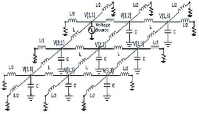
Homogenous periodic lumped-elements network as depicted in Fig. 1 can be constructed around one of the unit cells shown in Fig. 2. The interface between a conventional RH medium and a meta-material medium (LH) should include two types of unit cells.
Figure 1. RH L-C network.
Figure 1 shows an RH 3 × 3 unit-cells network in which each node is labeled as follows:
V(1,1), V(1,2), ..., V(3,3). This labeling is required when we use an ADS simulator.
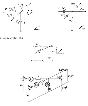
We can use the technique of auxiliary sources to give a general representation of a unit cell in which both the serial impedanceZ and shunt admittanceY can be composed of a combination of the elements
L, C, and R. So, each of the elements Z and Y will be replaced by an auxiliary source, as shown by Fig. 3.
Figure 2. RH/LH L-C unit cells.
Figure 3. L-C unit cell and its equivalent representation using auxiliary sources.
voltages and currents inside a unit cell, as given by the following system of Equation (1) ⎧ ⎪ ⎪ ⎨ ⎪ ⎪ ⎩
Ix+Iy+Iz−Ixejα−Iyejβ = 0
V x·ejα=V y·ejβ =Ez V x+Ex−rIx−Ez= 0
V y+Ey−rIy−Ez= 0
(1)
The system of equations can be rewritten in a matrix form of Eq. (2) labeled admittance matrix which relates the vector of currents to the vector of voltages, i.e., auxiliary sources.
Ix Iy Iz = 1 r
1 0 a
0 1 b
a∗ b∗ |a|2+|b|2
Ex Ey Ez (2)
wherea=e−jα(1−ejα);b=e−jβ(1−ejβ).
α andβ are the phase shifts between two cells along the X, Y axes. The admittance matrix can be rewritten as follows
¯
Y = 1
r
Δ = (X, Y, Z), is expressed as follows in Eq. (6)
SΔ= ZZΔ−Z0 Δ+Z0
(6)
Z0 is the characteristic impedance.
The determination of the spectral and spatial reflection coefficients in all the unit cells of the periodic circuit permits applying the iterative process that is based on the concept of incident and reflected waves A andB as in Eq. (7).
A=SB+A0 spatial domain
B = ΓA spectral domain (7)
The passage from one domain to another is done by the application of a Fast Fourier Transform and its inverse.
The running of the iterative process will be stopped until its convergence. Therefore, the voltage
E and currentJ inside each cell are given directly as follows in Eq. (8) ⎧
⎨ ⎩
Ex,y,z=√Z0 (Ax,y,z(i, j) +Bx,y,z(i, j))
Jx,y,z= √1Z
0(Ax,y,z(i, j)−Bx,y,z(i, j))
(8)
The modeling of RH/LH mediums by lumped elements requires the determination of the inductanceL and the capacitance C representing the permeability and the permittivity of the medium, respectively. According to the transmission line theory, the resolution of the telegrapher’s equations corresponding to RH/LH unit cells gives the propagation constant as follows in Eq. (9)
βRH= ω
Δl
LRHCRH
βLH =−
1
ωΔl√LLHCLH
(9)
Δlis the length of a unit cell which should be much smaller than the guided wavelength.
The index of refraction is then expressed in function of the propagation constant and the speed of light in vacuum as follows in Eq. (10)
nRH/LH= cβω =√μrεr (10)
Hence, we can write the refractive index of RH/LH mediums as Eqs. (11) and (12) respectively.
nRH = c Vφ =
√
LRHCRH
Δl√μ0ε0
(11)
nLH = Vc φ =−
1
ω2Δl√μ 0ε0
√
LLHCLH
(12)
Then,L and C parameters can be expressed as Eqs. (13) and (14)
LRH = μ0μrΔl; CRH=ε0εrΔl (13)
LLH =
1
ω2ε 0|εr|Δl
; CLH =
1
ω2μ
0|μr|Δl
The characteristic impedance is given by Eq. (15)
ZC =
LRH CRH
=
LLH CLH
= μ
0μr ε0εr
(15)
3. PRINCIPLE OF NEGATIVE REFRACTION BY THE INTERFACING BETWEEN RH/LH MEDIUMS
An infinite medium of wave propagation can be achieved by means of a finite medium bounded by matched impedances. Generally, mediums differ from each other by their permittivity and permeability. These two parameters are positive for conventional RH mediums [23, 24], which leads to a positive refractive index. Yet, they are both negative for meta-material mediums (LHM) [25, 26], which gives a negative refractive index. Thus, the wave propagation through the interface between mediums with different permittivity and permeability values should follow the Snell’s law of refraction in Eq. (16).
nisinθi=nrsinθr (16)
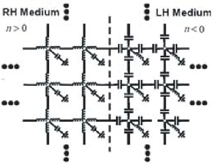
Figure 4 shows two interfaced RH/LH mediums with opposite refractive index signs.
Figure 4. Interfaced RH/LH lumped element networks.
The simulation of the above network using the WCIP method illustrates snell’s law of refraction. In fact, the two mediums are first chosen with the same index of refraction but with opposite signs, which is proved by Fig. 5 where the angles of incidence and refraction have the same absolute values.
This is to notice that all axes are labeled according to cell number, and the right vertical scales designate the units voltage or radians.
Figure 5 shows spherical wave fronts from the point source placed at (1, 1), which arrive at the level of the dipoter center plane at the right hand/center at the left hand (the plane x = 125). In the left-hand medium, we also observe wave fronts, of the same curvature as those observed in the right-hand medium, which seem to come from another point source symmetrical to the first one.
Secondly, the two mediums are chosen with different magnitudes of the index of refraction. We note in Fig. 6, for the value of the indexnLH =−2 of the left-hand medium, that the distance
between the wave fronts decreases. The curvature of the wave fronts in the left-hand medium is greater than that of the right-hand medium and seems to come from a point source located not symmetrically with respect to the emitting source (1, 1) but rather of a virtual source placed much further.
4. CHANNELING OF ELECTROMAGNETIC WAVES USING TRIANGULAR SHAPED META-MATERIAL MEDIUMS
Figure 5. Magnitude and phase of voltage distribution over two interfaced RH/LH lumped element networks with the index of refraction nRH = 1 and nLH = −1 which correspond to: CRH = 88.5 fF, LRH= 12.5 nH, CLH = 2 pF,LLH = 286 nH, Δl= 10 mm, f = 1 GHz.
Figure 6. Magnitude and phase of voltage distribution over two interfaced RH/LH lumped element networks with the index of refraction nRH = 1 and nLH = −2 which correspond to: CRH = 88.5 fF, LRH= 12.5 nH, CLH = 1 pF,LLH = 143 nH, Δl= 10 mm, f = 1 GHz.
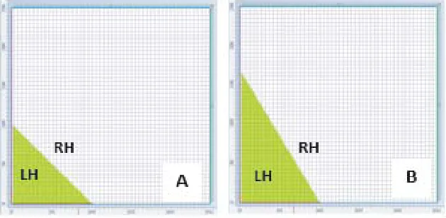
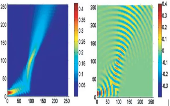
Figure 8. Schematic of triangular-shaped LH mediums interfaced with RH mediums. The total periodic circuit is excited by a line of voltage sources located at the left down corner. The index of refraction are nRH = 1 and nLH = −1 which correspond to: CRH = 0.354 pF, LRH = 50 nH, CLH = 0.5 pF, LLH = 71.5 nH, Δl= 20 mm,f = 1 GHz.
Figure 9. Absolute value of voltage distribution over the periodic circuitsAandB shown in Fig. 8 using the WCIP method: nRH = 1, nLH =−1,CRH = 0.177 pF, LRH = 25 nH, CLH = 1 pF,LLH = 143 nH,
Figure 10. Absolute and real values of voltage distribution over the periodic circuits Aand B shown in Fig. 9 using WCIP method.
The results of simulation using the WCIP method given by Fig. 8 show the same directions of the beam propagation, as depicted by the schematic principle in Fig. 7.
We can control the direction of the electromagnetic beam by either changing the slope angle of the inclined edge of the triangular-shaped LH medium as depicted in Fig. 9 or by changing the frequency. The results of simulation using the WCIP method are given in Fig. 10.
The results of simulation given by Fig. 10 are performed with the following parameters values:
nRH = 1, nLH = −1, CRH = 0.177 pF, LRH = 25 nH, CLH = 1 pF, LLH = 143 nH, Δl = 20 mm, f = 1 GHz/2 GHz.
5. CONCLUSION
We have numerically demonstrated the behavior of the electromagnetic field distribution inside RH/LH mediums using the WCIP method and an equivalent effective medium realized by L-C lumped elements. The WCIP method proves its accuracy to simulate very large periodic circuits of 256∗256 unit cells. It is clear that this method can resolve the problem of nodes labeling encountered with the ADS simulator when studying this kind of periodic circuits. Thus, the WCIP method can be used to analyze many meta-material-based applications, such as lenses and spatial filters.
REFERENCES
1. Veselago, V. G., “The electrodynamics of substances with simultaneously negative values of εand
μ,”Sov. Phys.-Usp., Vol. 10, 509–514, Jan.–Feb. 1968.
2. Alibakhshikenari, M., B. S. Virdee, A. Ali, and E. Limiti, “Based on CRLH metamaterials for wireless communication systems operating over UHF to C-band,” Radio Science, Vol. 53, No. 2, 154–165, Feb. 2018.
3. Alibakhshi-Kenari, M., M. Naser-Moghadasi, R. A. Sadeghzadeh, B. S. Virdee, and E. Limiti, “New CRLH-based planar slotted antennas with helical inductors for wireless communication systems, RF-circuits and microwave devices at UHF-SHF bands,” Wireless Personal Communications, Vol. 92, No. 3, 1029–1038, Feb. 2017.
5. Caloz, C., H. Okabe, H. Iwai, and T. Itoh, “Transmission line approach of left-handed materials,”
USNC/URSI Nat. Radio Science Meeting, 39, San Antonio, TX, Jun. 16–21, 2002.
6. Oliner, A. A., “A periodic-structure negative-refractive-index medium without resonant elements,”
USNC/URSI Nat. Radio Science Meeting, 41, San Antonio, TX, Jun. 16–21, 2002.
7. Grbic, A. and G. V. Eleftheriades, “Growing evanescent waves in negative-refractive-index transmission-line media,” Appl. Phys. Lett., Vol. 82, No. 12, 1815–1817, Mar. 2003.
8. Ozbay, E. and C. M. Soukoulis, “Observation of negative refraction and negative phase velocity in true left-handed metamaterials,” 36th European Microwave Conference, 2006, 959–962, IEEE, Sep. 2006.
9. Collin, R. E.,Foundations for Microwave Engineering, 2nd Edition, McGraw-Hill, Singapore, 1992. 10. Shelby, R. A., D. R. Smith, and S. Schultz, “Experimental verification of a negative index of refraction,” Science, Vol. 292, No. 5514, 77–79, New York, N.Y., Apr. 2001, doi:10.1126/science.1058847.
11. Alibakhshikenari, M., B. S. Virdee, P. Shukla, C. H. See, R. Abd-Alhameed, M. Khalily, F. Falcone, and E. Limiti, “Interaction between closely packed array antenna elements using metasurface for applications such as MIMO systems and synthetic aperture radars,”Radio Science, Vol. 53, No. 11, 1368–1381, Nov. 2018.
12. Alibakhshikenari, M., B. S. Virdee, P. Shukla, C. H. See, R. A. Abd-Alhameed, F. J. Falcone, and E. Limiti, “Meta-surface wall suppression of mutual coupling between microstrip patch antenna arrays for THz-band applications,” Progress In Electromagnetics Research Letters, Vol. 75, 105– 111, 2018.
13. Alibakhshi-Kenari, M., M. Naser-Moghadasi, R. A. Sadeghzadeh, B. S. Virdee, and E. Limiti, “Periodic array of complementary artificial magnetic conductor metamaterials-based multiband antennas for broadband wireless transceivers,”IET Microwaves, Antennas&Propagation, Vol. 10, No. 15, 1682–1691, Dec. 10, 2016.
14. Alibakhshi-Kenari, M., M. Naser-Moghadasi, R. A. Sadeghzadeh, and B. S. Virdee, “Metamaterial-based antennas for integration in UWB transceivers and portable microwave handsets,”
International Journal of RF and Microwave Computer-Aided Engineering, Vol. 26, No. 1, 88–96, Jan. 2016.
15. Ozbay, E., K. Guven, and K. Aydin, “Metamaterials with negative permeability and negative refractive index: Experiments and simulations,” Journal of Optics A: Pure and Applied Optics, Vol. 9, No. 9, S301, 2007.
16. Kishor, K., M. N. Baitha, R. K. Sinha, and B. Lahiri, “Tunable negative refractive index metamaterial from V-shaped SRR structure: Fabrication and characterization,” JOSA B, Vol. 31, No. 7, 1410–1414, 2014.
17. Islam, M. M., M. T. Islam, M. Samsuzzaman, M. R. I. Faruque, N. Misran, and M. F. Mansor, “A miniaturized antenna with negative index metamaterial based on modified SRR and CLS unit cell for UWB microwave imaging applications,”Materials, Vol. 8, No. 2, 392–407, 2015.
18. Titaouine, M., A. G. Neto, H. Baudrand, and F. Djahli, “Analysis of frequency selective surface on isotrop anisotrop layers using WCIP method,”ETRI Journal, Vol. 29, No. 1, 36–44, Feb. 2009. 19. Hajlaoui, E. A., H. Trabelsi, and H. Baudrand, “Periodic planar multilayered substrates analysis using wave concept iterative process,”Journal of Electromagnetic Analysis and Applications, Vol. 4, 118–128, 2012.
20. Aroussi, S., L. Lassaad, S. Noureddine, et al., “Efficient analysis of complex FSS structure using the WCIP method,” Journal of Electromagnetic Analysis and Applications, Vol. 3, No. 11, 447, 2011.
21. Hajri, J., et al., “Efficient study of substrate integrated waveguide devices,” World Academy of Science, Engineering and Technology, International Journal of Mechanical, Aerospace, Industrial, Mechatronic and Manufacturing Engineering, Vol. 9, No. 2, 381–385, 2015.