RESONANT DIFFRACTION FROM A GRATING ON A PARAMAGNETIC LAYER WITH FREQUENCY DISPER-SION
S. B. Panin
Department of Diffraction Theory and Diffraction Electronics Institute for Radiophysics and Electronics of NAS of Ukraine 12, Academic Proskura Str., Kharkov 61085, Ukraine
E. D. Vinogradova
Department of Mathematics Macquarie University
NSW 2109, Sydney, Australia
A. Y. Poyedinchuk and S. I. Tarapov
Department of Diffraction Theory and Diffraction Electronics Institute for Radiophysics and Electronics of NAS of Ukraine 12, Academic Proskura Str., Kharkov 61085, Ukraine
Abstract—Theoretical results on the plane electromagnetic wave diffraction from a structure as a strip periodic grating on a paramagnetic layer, the permeability of which possesses negative real part in the microwave band, are obtained using analytical regularization based on the solution to the Riemann-Hilbert problem. The effect of the resonant transmission accompanied by extremely high absorption is thoroughly studied across the frequency band of the surface waves of the paramagnetic layer placed in the biasing magnetic field. This effect is caused by the surface waves of the layer excited resonantly by the plane incident wave with the diffraction grating present. The resonant frequency is electronically tuned by the biasing magnetic field.
1. INTRODUCTION
Artificially structured materials have the exciting potential to revo-lutionise communication technology because they can be engineered for applications in microwave and optical devices. Among such com-posite materials that are very popular now are the so called meta-materials [1, 2], which at certain frequency are capable of exhibiting anomalous refraction with negative real-valued permittivity and per-meability due to their frequency dispersion. Also materials with one negative constitutive parameter (permittivity or permeability) have attracted much interest [3, 4].
The ever growing demand for better operating characteristics, extended capabilities and new functions of today’s microwave devices is the driving force behind the integration of composite materials in modern microwave technology. Although periodic structures such as diffraction gratings have a long history, their resonant behaviour in combination with composite media is rather novel and theoretically interesting as well as exciting for technological developments [5–7]. A rather novel study carried out in papers [8–10] has shown that the incident wave energy can be effectively absorbed in a resonant way by the structure consisting of a diffraction grating and absorbing medium with one of the constitutive parameters negative. For simplification the frequency dispersion of the constitutive parameters was not considered in those works.
In the present paper, we study diffraction of a plane wave by a strip grating lying on an absorptive layer whose permeability is frequency dependent and has a negative real part in the microwave band. This diffraction problem is mathematically solved using an Analytical Regularization [11, 12] based on the Riemann-Hilbert problem method [13], and the obtained solution thus admits a rigorous and provably accurate numerical treatment in the resonant domain.
partial waves of spatial spectrum. Upon certain conditions the grating surface harmonics from this superposition are able to excite the surface waves of the layer. When this happens we observe the energetically pronounced resonant regimes with interesting applied properties; one of them, the regime of resonant transmission with extremely high absorption, is studied here. The property of this regime can be used for creating novel devices, non-reflecting coatings, and microwave antenna components, the characteristics of which are electronically tunable by the biasing magnetic field.
2. PROBLEM FORMULATION
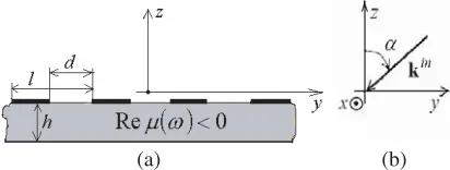
The geometry of the structure is shown in Fig. 1(a). A periodic grating of infinitely thin and perfectly conducting strips parallel to the OX axis lies on the plane layer of paramagnetic material with frequency dispersive relative permeabilityμ=μ(ω) and fixed relative permittivity ε. The grating is placed in the plane z= 0, its period is
l, and the slot width is d. The thickness of paramagnetic layer equals
h.
(a) (b)
Figure 1. The structure geometry (a) and the wave incidence (b).
The interaction of electromagnetic field with paramagnetic material under the condition of electron-spin resonance results in the frequency dispersion of its permeability. The frequency behaviour of the complex valued permeability follows from the macroscopic model of the medium based on the well-known Bloch motion equation, see for example [14, 15]. In the so-called “slowly passing” resonance line approximation (i.e., for the stationary case) and for small amplitude of alternating field, the permeability of the paramagnetic material
μ=μ+iμ can be presented in the following form [14, 16]:
μ(ω) = 1 + 2πχ0
ω ω0−1
1 (ω0τ)2 +
ω ω0−1
2, μ(ω) =
2πχ0
1
ω0τ+ω0τ
ω ω0−1
whereω is the frequency of the incident wave,ω0 =γB0 is theLarmor
frequency of the electron-spin precession in the biasing magnetic field
B0,γ is the gyromagnetic ratio,χ0is the static magnetic susceptibility,
and τ is a cross relaxation time.
Throughout the paper we suppose, that the paramagnetic layer has the following parameters: τ = 10−8s, χ0 = 1, and ε = 10.0. An
example of such a medium is ruby, where the electron-spin resonance phenomenon occurs for one of allowed levels. Suppose that an external magnetic field B0 = 2.697 T causing precession with the frequency ω0 = 4.71×10¹¹rad s−1 is applied to the paramagnetic layer, and also
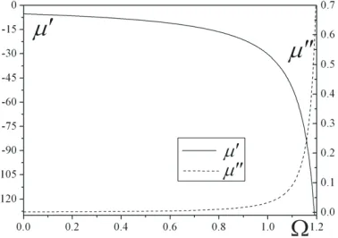
suppose that the grating period is l = 5×10⁻³m, and d/l = 0.5. Under these assumptions the frequency dispersion of permeability is shown in the Fig. 2 as a function of non-dimensional frequency Ω = λl = 2lπ√ε0μ0ω, where λ is the wave length in vacuum and the
periodl is given above. Thus, due to the magnetic interaction, in the long-wave (l < λ) and in the resonant (l∼λ) ranges of the grating, the real part of layer permeability has negative value, while the positive imaginary part describes the losses in the medium.
Figure 2. The frequency dispersion of the permeability μ = μ +
iμ as a function of the non-dimensional frequency parameter Ω =
1 2π
√ε
0μ0ω (l= 5×10⁻³m).
The monochromatic plane wave of E-polarization (E||OX): Ein =E0exp
ikinr−ωt,Hin=H0exp
ikinr−ωt is obliquely incident on the grating such that
E0 = (˜e, 0, 0), H0=
0, −e˜ ρcosα,
˜
e
ρsinα , (2)
where ˜e is a complex amplitude of the electric field, α ∈
−ω√ε0μ0(0,sinα,cosα) and the OZ axis (see Fig. 1(b)), and ρ =
μ0/ε0 is the impedance of free space. We seek the diffracted field.
The incident field is x-independent, and the grating extends infinitely in the x-direction, thus the problem is solvable in two-dimensional terms (∂/∂x≡0). The constitutive parameters of media are scalar permittivity and permeability. Therefore, the considered problem can be separately solved for E- or H-polarization (HOX) cases. One can prove that the diffracted field has the same polarization as the incident wave.
For solution existence and uniqueness, the conditions to satisfy are: Maxwell’s equations, radiation condition, boundary conditions, quasiperiodicity condition, and condition of the field energy finiteness within any confined volume of space.
3. SOLUTION
The grating periodicity along the OY axis allows us to expand the solution in a Fourier series. The series substitution in the Helmholtz equation gives the field representation which coincides with the Rayleigh expansion of the diffracted field in an infinite series of partial waves of the spatial spectrum. Let the indexj = 1 correspond to the upper and lower half-spaces, andj= 2 to the paramagnetic layer, then the propagation constant of then-th harmonic isξn= 2πn/l−k1sinα
in the y-direction and ζn(j) =
(kj)2−(ξn)2
Im
ζn(j)
≥0
in the
z-direction, where k1 = ω√ε0μ0 and k2 = k1
εμ(ω). For example, the field electrical component (which is parallel to theOX-axis) is
Ex= ˜eexp(−ik1(ysinα+zcosα)) + +∞
n=−∞ anexp
iζn(1)z
exp(iξny)
0< z;
Ex=
+∞
n=−∞
x+n exp
iζn(2)z
+x−n exp
−iζn(2)z
exp(iξny), −h < z <0;
Ex=
+∞
n=−∞ gnexp
−iζn(1)z
exp(iξny), z <−h,(3)
wherean, x±n, andgn are the unknown complex amplitudes of then-th spatial harmonics in the corresponding partial domains.
Applying the boundary conditions to each surface (z = 0 and
domains. Also using the boundary conditions provides the system of functional equations to determine the unknown coefficients, which is a system of dual series equations involving trigonometric functions. This system is a particular case of the systems obtained and solved in work [7]. It is equivalent to the operator equation of the first kind [17] in the Hilbert space given by the Meixner condition [18]. Thus, the system is ill-conditioned [19] and, generally speaking, the truncation technique cannot be employed [20]. A direct usage of the methodological results from [7] converts the system to the following form
⎧ ⎪ ⎪ ⎪ ⎪ ⎪ ⎪ ⎪ ⎪ ⎪ ⎪ ⎪ ⎪ ⎪ ⎪ ⎨ ⎪ ⎪ ⎪ ⎪ ⎪ ⎪ ⎪ ⎪ ⎪ ⎪ ⎪ ⎪ ⎪ ⎪ ⎩ ∞
n=−∞
n=0
Xnexp (inϕ) +θX0= 0, δ <|ϕ|< π
∞
n=−∞
n=0 |n|
n Xnexp(inϕ) +θX0 = ∞
n=−∞
pnXnexp(inϕ), |ϕ|< δ
∞
n=−∞
n=0
(−1)n
n+θXn+X0 = 0, ϕ=π
(4)
where Xn =snx+
n; the coefficients sn and pn are expressible in terms of structure parameters and frequency. The value θ ∈ [−0.5,0.5) is chosen so that −θ = m0 + Ω sinα, where m0 is the nearest integer
to −Ω sinα. In (4), we introduced ϕ = 2πy/l, δ = πd/l; thus the inequality |ϕ|< δ indicates the grating slot, and δ <|ϕ|< π refers to the strip. Upon sn and pn presentations which can be obtained from [7], it can be shown that
pnXn =
|n|→∞σnn
−2, (5)
where |σn|2 <∞. The rest of the unknown complex amplitudes in all domains can be expressed in terms ofx+n.
system of linear algebraic equations
θx+0 =
+∞
p=−∞
γp0V0pxp++b0, x+n= +∞
p=−∞
γpnVnpx+p+bn, (6)
where the values γpn, Vnp, and bn are given in [7, 13]. From the asymptotic estimates of the coefficients γpn ∼ 1/p2, and from the
behaviour of Vnp (e.g., for n = p we roughly have Vnp < const
√ |p| √
|n||n−p|
as |n|,|p| → ∞), it follows that (6) is equivalent to a Fredholm system of the second kind. As known, such a system can be solved by a truncation procedure with any preassigned accuracy. Thus the analytical regularization allows us to get rid of the ill-conditioning and arrive at the form admitting effective numerical treatment.
4. NUMERICAL RESULTS
Let us introduce the reflection (R0) and transmission (T0) coefficients
in the zero order of the spectrum; these determine the relative fractions of scattered energy density spread from the structure to the upper and lower half-spaces by the propagating zero harmonics with the corresponding wave vectors kR, T0 =
0, ξ0,±ζ0(1)
.
In the frequency band ΔΩ∈[0,1/(1 + sinα)], only the zero order harmonics spread energy in the half-spaces, all others (n = 0) have imaginary part ofζn(1), and thus exponentially decay from the structure. These decaying harmonics travel along the grating (axisOY) with the phase velocities vyn=cΩ/(n−Ω sinα), wherec is the velocity of light in vacuum; the totality of these surface harmonics does not transfer the field energy even along the surface. The paramagnetic layer with negative permeability does not support traveling volumetric waves; all the harmonics in (3) for the cdomain −h < z <0 exponentially decay away from the layer boundaries. The frequency band ΔΩ determines the single-mode regime of diffraction which we actually consider here. For this regime in the far field region, the diffracted field is represented by only one propagation plane wave with energy fraction R0 (for the
half-space z > 0) and T0 (for z < −h). We suppose below that the
paramagnetic layer is thin (i.e., h/λ 1), and let ˜e = 1; thus the energy dissipation in the paramagnetic layer is defined by the loss coefficientL0 = 1−(R0+T0) for the single-mode regime.
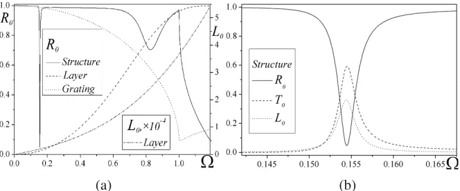
grating, and the structure. In what follows, the truncation number of system (6) is 25. We observe the sharp minimum of the modulus of reflection coefficient at Ω0 ≈ 0.154 (see Fig. 3(a)) for diffraction
from the structure. At the “long wave” range l/λ 1, the single grating nearly completely reflects theE-polarized incident wave, while the single layer is almost transparent there.
The reflection minimum for the structure corresponds to the resonance wave transmission with high absorption (≈ 37%) in the rather thin paramagnetic layer (h/λ≈3×10−3), the losses of which are characterized by the dissipation factor tanδ =|μ/μ| ≈ 2.82×10⁻⁴ (see Fig. 2, and Fig. 3(b)). The wave losses in the layer without grating are only about 2×10⁻³% for this frequency Ω0 (see Fig. 3(a)).
The paramagnetic layer can be considered as an open resonant structure possessing eigen-frequencies and relevant eigen-oscillations. The study of the eigen-value problem for the paramagnetic layer shows that it has a surface eigen-oscillation in the form of surface waves [10, 21]. These surface waves cannot be excited by an incident plane wave. Being a periodical inhomogeneity, the grating converts the incident plane wave into an infinite superposition of spatial harmonics, and thus makes possible the excitation of oscillations in the layer [22]. On the other hand, the grating makes different oscillations interact with each other and so establishes an electrodynamical coupling between different Floquet harmonics both inside and outside the layer. In a condition of synchronism, when, for a certain frequency, the phase velocities of one of the grating surface harmonics and the surface wave of the layer are close enough, effective excitation of the layer surface oscillations takes place. On the whole, the realization of this
(a) (b)
Figure 3. Reflection (R0), transmission (T0) and loss (L0) coefficients
Figure 4. Reflection coefficient R0 (contours of equal magnitude)
versus frequency Ω and relative thicknessh/lof the paramagnetic layer (d/l = 0.5,α= 0◦).
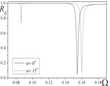
Figure 5. Reflection coefficient R0 versus frequency Ω in the oblique
wave incidence case (d/l= 0.5,h/l = 0.02).
resonant condition corresponds to the eigen-regime of the grating-layer structure.
The value of reflection coefficient R0 as a function of the
non-dimensional frequency and the relative thickness of the paramagnetic layer h/l is represented in Fig. 4. In this picture we observe a lengthy domain of the resonant transmission with high absorption. The transmission frequency increases nearly linearly as the layer thickness decreases.
Figure 6. Reflection coefficient R0 versus frequency Ω in the
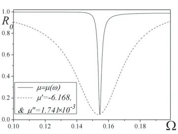
dispersive and non dispersive cases (d/l = 0.5,h/l= 0.02, α= 0◦).
−n harmonics have different phase velocities vny (since α = 0◦), and both are able to excite layer surface waves at certain frequencies, so that two absorption resonances appear instead of one.
The influence of the frequency dispersion of the layer permeability, given in the form (1), on the development of the absorption resonance is compared to the reflection obtained with constant constitutive parameters, which values give the same resonance, in Fig. 6. Varying the dispersion character of the permeability can make the reflection minimum considerably sharper, because of the essentially resonant nature of the phenomenon. Ignoring the dispersion of the permeability results in omitting important spectral features of the paramagnetic layer; in this case we mainly observe the contribution of resonant properties of the grating only. The combination of the two strongly resonant systems, the grating and the layer, into one structure, significantly complicates the spectral characteristics and changes the reflection minimum width.
The frequency dependence of the reflection coefficient for the layer permeability, given by (1), is shown in Fig. 7 for different values of layer permittivity. The frequency of the absorption resonance depends slightly on the layer permittivity; the spectrum of the surface waves in the layer is principally determined by the permeability. As follows from (1), the layer permeability, and thus the frequency of absorption resonance, can be effectively controlled by electronically adjusting the biasing magnetic fieldB (see Fig. 8).
Figure 7. Reflection coefficient R0 versus frequency Ω for different
values of layer permittivity ε(d/l = 0.5,h/l= 0.02, α= 0◦).
Figure 8. Reflection coefficient R0 (contours of equal magnitude)
versus frequency Ω and relative biasing magnetic field B/B0 (B0 =
2.697 T, d/l= 0.5,h/l = 0.02,α= 0◦).
from the picture, at the resonant frequency Ω0, the amplitudes of the
Figure 9. Modulus of the first complex amplitudes|an|of the reflected field versus frequency Ω (d/l = 0.5,h/l= 0.02).
as a result we observe the regime of the resonance transmission with high absorption. This is a qualitative model of the regime; a detailed quantitative analysis of this complicated resonant regime may be based on the rigorous solution to the spectral problem for the structure, and this is the subject of our next paper.
The diffraction process for the structure with conventional magnetodielectric with positive real parts of the constitutive parameters is quite different to that of paramagnetic materials with negative real permeability. In the conventional magnetodielectric, at least one (the zero) volumetric harmonic always propagates, and the main contribution to the diffraction process (both spectral and absorption features) is made just by the propagating volumetric harmonics.
5. CONCLUSION
Using the analytical regularization based on the Riemann-Hilbert problem method, we have solved the problem of plane electromagnetic wave diffraction from the structure consisting of a strip grating and paramagnetic layer with frequency dispersive material, which has permeability of negative real part in the microwave band. The layer with such dispersion possesses surface waves, which can be excited by surface harmonics produced by the grating.
surface wave. This phenomenon is of resonance character, and it is a response to the oscillatory excitations which are close to the structure eigenmodes. The powerful surface field localized at the grating-layer interface in the resonance is responsible for transmission and extremely high absorption, which occurs just at the surface but not in the layer volume.
The necessity of considering the dispersion character of the constitutive parameters for adequate description of electromagnetic process was demonstrated. In the oblique incidence case, the phenomenon of splitting of the absorption resonance was shown.
The quality factor of the resonant regime considered is quite high. Such structures, with a narrow and tunable pass-band, are promising for application, for example, as filters or absorbing devices with electronically tunable frequency.
ACKNOWLEDGMENT
The work is partially supported by STCU Project #3727.
REFERENCES
1. Engheta, N. and R. W. Ziolkowski, “A positive future for double-negative metamaterials,”IEEE Trans. on Microwave Theory and Tech., Vol. 53, No. 4, 1535–1556, 2005.
2. Pendry, J. B., “Negative refraction,”Contemporary Phys., Vol. 45, No. 3, 191–202, 2004.
3. Pendry, J. B., A. J. Holden, W. J. Stewart, and I. Youngs, “Extremely low frequency plasmons in metallic meso structures,”
Phys. Rev. Lett., Vol. 76, 4773–4776, 1996.
4. Pendry, J. B., A. J. Holden, D. J. Robbins, and W. J. Stew-art, “Magnetism from conductors and enhanced nonlinear phe-nomena,” IEEE Trans. on Microwave Theory and Tech., Vol. 47, 2075–2084, 1999.
5. Uehara, M., K. Yashiro, and S. Ohkawa, “Diffraction of plane waves from a strip grating on a ferrite substrate,” Proc. Asia Pacific Microwave Conference, 177–180, 1997.
6. Panin, S. B., P. D. Smith, and A. Y. Poyedinchuk, “Elliptical to linear polarization transformation by a grating on a chiral medium,” Journal of Electromagnetic Waves and Applications, Vol. 21, No. 13, 1885–1899, 2007.
diffraction by a grating with a chiral layer,” Radiophysics and Quantum Electronics, Vol. 45, No. 8, 629–639, 2002.
8. Melezhik, P. N., A. Y. Poyedinchuk, Y. A. Tuchkin, and N. P. Yashina, “Periodic surface of materials with single and double negative parameters: Absorption resonances,” Proc. Int. Kharkiv Symp. Phys. and Engineering of Microwaves, Millimeter, and Submillimeter Waves, 311–313, MSMW’04, Kharkiv, 2004. 9. Granet, G., M. Ney, N. Yashina, A. Poyedinchuk, and S. Panin,
“Electromagnetic wave diffraction by periodic structures with metamaterials: Surface wave resonance,” Proc. 13th Int. Symp. on Antennas, 8–10, JINA’04, Nice, 2004.
10. Kusaykin, O. P., P. N. Melezhik, A. Y. Poyedynchuk, and O. S. Troschylo, “Absorbing properties of a negative permittivity layer placed on a reflecting grating,”Progress In Electromagnetics Research, PIER 64, 135–148, 2006.
11. Poyedinchuk, A. Y., Y. A. Tuchkin, and V. P. Shestopalov, “New numerical-analytical methods in diffraction theory,”Mathematical and Computer Modelling, Vol. 32, 1026–1046, 2000.
12. Panin, S. B., P. D. Smith, Y. A. Tuchkin, E. D. Vinogradova, and S. S. Vinogradov, “Regularization of the Dirichlet problem for Laplace’s equation: Surfaces of revolution,” Electromagnetics, Vol. 29, No. 1, 53–76, 2009.
13. Agranovich, Z. S., V. A. Marchenko, and V. P. Shestopalov, “The diffraction of electromagnetic waves from plane metallic lattices,”
Sov. Phys. Tech. Phys., Vol. 7, 277–286, 1962.
14. Bloch, F., “Nuclear induction,” Phys. Rev., Vol. 70, 460–474, 1946.
15. Kittel, C., Introduction to Solid State Phys., Wiley & Sons, New York, 1994.
16. Tarapov, S., T. Bagmut, A. Granovsky, V. Derkach, S. Nedukh, A. Plevako, S. Roschenko, and I. Shipkova, “Electron spin resonance properties of magnetic granular GMI-nanostructures in millimetre waveband,”Intern. Journal of Infrared and Millimeter Waves, Vol. 25, No. 11, 1581–1589, 2004.
17. Kantorovich, L. V. and G. P. Akilov, Functional Analysis in Normed Spaces, Pergamon Press, New York, 1982.
18. Meixner, J., “The behaviour of electromagnetic field at edges,”
IEEE Trans. on Antennas and Propagation, Vol. 20, 442–446, 1972.
20. Mittra, R. and S. W. Lee,Analytical Tech. in the Theory of Guided Waves, The Macmillan Company, New York, 1971.
21. Brovenko, A., P. N. Melezhik, A. Y. Poyedinchuk, N. P. Yashina, and G. Granet, “Surface resonances of metal stripe grating on the plane boundary of metamaterial,” Progress In Electromagnetics Research, PIER 63, 209–222, 2006.