Multiband Compact Low SAR Mobile Hand Held Antenna
Haythem H. Abdullah* and Kamel S. Sultan
Abstract—With the vast emergence of new mobile applications, multiband operation in a compact size is mandatory for market penetration. In this paper, a new mobile handset antenna suitable for both mobile and wireless LAN services is presented. The antenna operates for most of the mobile applications such as the GSM 900, DCS 1800, PCS 1900, UMTS 2100, and most of the LTE bands, especially the low frequency LTE 700 band at−10 dB. The antenna also supports the WIMAX, WLAN, and the ISM bands. The antenna not only has a compact size, but also supports a low SAR radiation at all the operating frequencies. The antenna consists of two concentric open rings that act as quarter wavelength monopoles. The inner ring radiates at 900 MHz, while the outer ring radiates at 700 MHz. The inner ring works as a monopole radiator as well as a slot radiator fed by another rectangular monopole. The advantage of the slot is that it supports a wide range of modes that by its role open the radiation band from 1.65 to 3.6 GHz. The antenna meets three challenging parameters: compact size, multiband operation including low frequency bands, and low SAR radiation. Good agreement is noticed between the experimental and simulated results.
1. INTRODUCTION
With the early advent of mobile handset devices there are great competitions on how to introduce smaller, slimmer, and lighter handset devices. Also, the future development of the personal communication devices will aim to provide image, voice and data communication at any time. This indicates that mobile devices are required to support different technologies and operate in different frequency bands.
The LTE (Long Term Evolution) is a new high-performance air interface standard for cellular mobile communication systems. It is the 4th generation (4G) of radio technologies to increase the capacity and speed of mobile telephone networks [1–6]. In order to include 4G in the hand held devices, Young et al. [3] introduced an octa-band antenna with more compact size of 46×7×11 mm3. The antenna operating bands are; the LTE 700, GSM 850, GSM 900, DCS 1800, PCS 1900, WCDMA 2100, LTE 2300, and the LTE 2500 bands at (−6 dB). Recently, Wong and Chen [4] proposed a small-size printed loop antenna integrated with two stacked coupled-fed shorted strip monopoles for multiband operation in a mobile phone that covers LTE 700, LTE 2300, LTE 2500, GSM 850, GSM 900, DCS 1800, PCS 1900, and UMTS bands (at −6 dB) with size reduction relative to [3]. Guo et al. [5] introduced a new compact multiband antenna that covers new bands than [3–5], GSM 900, DCS 1800, PCS 1900, UMTS 2100, and some LTE bands (FDD-LTE band 1–6, 8–10 and TDD-LTE band 19, 20, 33–37) [1] with dimensions of 50×15×4 mm3.
Zhai et al. [7] introduced a novel compact printed antenna for triple-band WLAN/WiMAX applications that consists of three simple circular-arc-shaped strips with size 18×37×1 mm3. Also, Chen and Jhang [8], introduced a compact antenna that consists of a direct-fed monopole with a chip inductor, a grounded strip, and a coupled-fed monopole with a distributed inductor and dimensions
Received 16 June 2014, Accepted 15 September 2014, Scheduled 30 September 2014
presents the conclusions for this research.
2. ANTENNA DESIGN
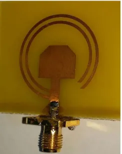
The proposed antenna is a planar printed antenna with compact dimensions of (26×30×1.5) mm3. The antenna can be easily integrated in small and sleek mobile device. Figure 1 shows the geometry of the proposed antenna. All the labeled dimensions are tabulated in Table 1. A prototype of the antenna is fabricated over FR4 substrate (εr = 4.5) with 1.5 mm thickness and loss tangent of 0.025 as shown in Figure 2.
The proposed antenna is composed of a planar monopole and two arc rings. The monopole antenna is of rectangular shape. The electrical length of the monopole is a quarter-wavelength at 2100 MHz. The inner arc acts as a monopole radiator at the 900 MHz and at the same time acts as a cavity resonator fed by the rectangular monopole that radiates in the upper frequency bands. The electrical length of the inner arc is optimized to resonate at 900 MHz. The optimized length of the inner line is 58.6 mm and the electrical length of the outer arc is optimized to resonate at 700 MHz with length 70.2 mm.
(a) (b)
Figure 1. Geometry of the proposed antenna. (a) Front. (b) Back.
Table 1. Parameters of the proposed antenna (All dimensions in mm).
Parameter L1 L2 L3 L4 L5 L6 R1 R2 S1 S2 W1 W g Lg
Figure 2. Photo of the fabricated antenna.
3. SIMULATED AND MEASURED RESULTS
The proposed antenna is simulated using the CST Microwave Studio 2012. Figure 3 shows a comparison between the simulated and measured results of the return loss. The simulated and the experimental results ensure that the antenna covers all the aforementioned mobile and wireless applications bands. Taking the 10 dB return loss reference, the antenna operates in the three bands from 685 to 750 MHz, from 872 to 975 MHz, and from 1.65 to 3.6 GHz.
One of the very important parameters that should to be considered is the size of the ground plane. By simulating the antenna at different ground sizes, it is noticed that the length of ground plane affects the matching slightly as shown in Figure 4. So, the proposed design is suitable for different hand held devices with different sizes.
The values of the first and second resonant frequencies are controlled by adjusting the total length of the outer and inner arcs while the third band is controlled by adjusting the dimensions of monopole radiators or the radius of the inner arc. Figure 5 shows the measured and simulated radiation patterns
Figure 3. The measured and simulated return loss.
Figure 4. Return loss by varying the ground length, Lg.
Table 2. Gain and the radiation efficiency of the proposed antenna.
F (GHz) 0.7 0.9 1.8 2.1
Gain dBi Simulated 2.1 1.9 3.1 3.4
Measured - 1.7 2.9 3
Radiation Efficiency % Simulated 71 82 77.2 82.6
1.8
2.1
Figure 5. The Radiation pattern (in dB) in theXZ andY Z planes. The antenna is in theXY plane. Simulated (solid line)-Measured (dash line).
at frequencies 0.9, 1.8 and 2.1 GHz. Radiation pattern measurements were carried out using SATIMO Anechoic antenna chamber where the available frequency range starts from 0.8 GHz. Table 2 shows the values of gain and radiation efficiency of the proposed antenna.
4. MOBILE PACKAGING
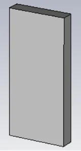
Figure 6. Mobile handheld with packaging. Figure 7. Simulated return loss with and without packaging.
0.019. The total dimensions of the mobile are (136.6×70.6×8.6) mm3 and its wall thickness is 1 mm as shown in Figure 6. Figure 7 shows a comparison between the simulated return loss of antenna with and without packaging. The results ensure that the antenna covers all the operating bands in both cases.
5. SAR CALCULATIONS
One of the important issues for any new mobile handset antenna is to follow the standard guidelines for the specific absorption rate (SAR) within the human head. As the use of the mobile phone is increased, the research on the health risk due to the electromagnetic (EM) fields generated from wireless terminals is widely in progress. Many factors may affect the EM interaction while using cellular handset in close proximity to head and hand. Therefore, some regulations and standards have been issued to limit the radiation exposure from the mobile handsets not only to decrease the SAR but also to increase the antenna systems efficiency.
The SAR limit specified in IEEE C95.1: 2005 has been updated to 2 W/kg over any 10-g of tissue [13], which is comparable to the limit specified in the International Commission on Non-Ionizing Radiation Protection (ICNIRP) guidelines [14]. The output power of the cellular phone model need to be set before SAR is simulated. In this paper, the output power of the cellular phone is set to 500 mW at the operating frequencies of 0.7, 0.9, 1.8, and 2.1 GHz. The SAR values are calculated according to the 10 gram standard of the human tissue mass. The SAR calculations are done using the CST 2012 commercial package with Hugo model CST Microwave Studio [15]; the tissues that are contained
(a) (b) (c) (d)
have relative permittivities and conductivities, according to [16, 17]. The tissues frequency dispersive properties are taken into consideration.
The Cellular Telecommunications and Internet Association (CTIA) has proposed several body test cases for a mobile phone as shown in Figure 8; mobile handset in free space, browsing mode (antenna between human fingers), talking position (0.5 mm distance between human head and antenna), and talking position with hand [18]. Figure 9 shows the return loss of the antenna in the four different cases. The primary effect of the hand, and head are little shift and little degradation of the impedance matching. However, the impedance matching over the operating bands is still acceptable for practical applications of the mobile phone.
Table 3 shows the averaged 10 g SAR at the aforementioned operating frequencies when the antenna is in close proximity to the body.
Table 3. SAR values of the proposed antenna (Talking position with hand).
F (GHz) 0.7 0.9 1.8 2.1
SAR (W/kg)-10 g Without Packaging 0.98 0.84 0.8 1.2
With Packaging 0.72 0.61 0.57 0.95
6. CONCLUSION
A new compact planar antenna design that supports most of the operating mobile services, ISM applications, and wireless communication services is introduced. The SAR values of the antenna satisfy the standard safety guidelines. The antenna has more compact size compared to other published antennas. The antenna was simulated using the CST simulator and fabricated using the photolithographic technique. Very good agreement is obtained between the simulated and experimental results.
REFERENCES
1. Sesia, S., I. Toufik, and M. Baker, LTE — The UMTS Long Term Evolution: From Theory to Practice, Wiley, Chichester, U.K., 2009.
2. Bhatti, R. A., S. Yi, and S. Park, “Compact antenna array with port decoupling for LTE-standardized mobile phones,”IEEE Antennas and Wireless Propagation Letters, Vol. 8, 1430–1433, 2009.
4. Wong, K. L. and W. Y. Chen, “Small-size printed loop-type antenna integrated with two stacked coupled-fed shorted strip monopoles for eight-band LTE/GSM/UMTS operation in the mobile,” Microwave and Optical Technology Letters, Vol. 52, No. 7, 1471–1476, Jul. 2010.
5. Guo, Q., R. Mittra, F. Lei, Z. Li, J. Ju, and J. Byun, “Interaction between internal antenna and external antenna of mobile phone and hand effect,”IEEE Trans. on Antennas and Propag., Vol. 61, No. 2, Feb. 2013.
6. 3GPP, “3rd generation partnership project; technical specification group radio access network; Evolved Universal Terrestrial Radio Access (E-UTRA); User Equipment (UE) radio transmission and reception (Release 10),” 3GPP TS36.101 V10.4.0, Table 5.5-1 E-UTRA, Sep. 2011.
7. Zhai, H., Z. Ma, Y. Han, and C. Liang, “A compact printed antenna for triple-band WLAN/WiMAX applications,” IEEE Antennas and Wireless Propagation Letters, Vol. 12, 65– 68, 2013.
8. Chen, W. S. and W. C. Jhang, “A planar WWAN/LTE antenna for portable devices,” IEEE Antennas and Wireless Propagation Letters, Vol. 12, 19–22, 2013.
9. Chu, F. H. and K. L. Wong, “Internal coupled-fed dual-loop antenna integrated with a USB connector for WWAN/LTE mobile handset,” IEEE Trans. on Antennas and Propag., Vol. 59, No. 11, 4215–4221, Nov. 2011.
10. Chiu, C.-W., C.-H. Chang, and Y.-J. Chi, “A meandered loop antenna for LTE/WWAN operations in a smart phone,”Progress In Electromagnetics Research C, Vol. 16, 147–160, 2010.
11. Wong, K. L., W. Y. Chen, C. Y. Wu, and W. Y. Li, “Small-size internal eight-band LTE/WWAN mobile phone antenna with internal distributed LC matching circuit,”Microw. Opt. Technol. Lett., Vol. 52, 2244–2250, 2010.
12. Kang, T. W. and K. L. Wong, “Chip-inductor-embedded small-size printed strip monopole for WWAN operation in the mobile phone,”Microw. Opt. Technol. Lett., Vol. 51, 966–971, 2009. 13. IEEE C95.1-2005, “IEEE standards for safety levels with respect to human exposure to radio
frequency electromagnetic fields, 3 kHz to 300 GHz,” Institute of Electrical and Electronics Engineers, New York, 2005.
14. International Non-Ionizing Radiation Committee of the International Radiation Protection Association, “Guidelines on limits on exposure to radio frequency electromagnetic fields in the frequency range from 100 kHz to 300 GHz,” Health Physics, Vol. 54, No. 1, 115–123, 1988.
15. CST Microwave Studio Suite 2011 User’s Manual, www.cst.com.
16. Gabriel, S., R. W. Lau, and C. Gabriel, “The dielectric properties of biological tissues. II. Measurements in the frequency range 10 Hz to 20 GHz,” Phys. Med. Biol., Vol. 41, 2251–2269, 1996.
17. Gabriel, C., “Tissue equivalent material for hand phantoms,”Phys. Med. Biol., Vol. 52, 4205–4210, 2007.