Analysis of 12-Pulse Rectifier with Active Inter-Phase Reactor
with Fuzzy Control Based Circulating Current
Jaddu Naga Sudeep & Rama Krishna Perla
1M.Tech(Student), Kakinada Institute of Technological Sciences Affiliated to JNTUK ,KAKINADA, Andhra Pradesh,
India.
2Assistant Professor, Kakinada Institute of Technological Sciences Affiliated to JNTUK ,KAKINADA, Andhra Pradesh,
India.
ABSTRACT: This paper analyzes the effect of circulating current with amplitude and phase on the line current of 12 pulse rectifier with the combination of the active inter phase reactor. Therefore the input line current and the total harmonic distortion will be calculated by using fuzzy controller under various amplitude and phases of the circulating current. According to the calculation results the effect of the circulating current will be analyzed. The fuzzy controller is the most suitable for the human decision-making mechanism, providing the operation of an electronic system with decisions of experts. Here fuzzy is compared with the other controller and later we analysis the performance of the system when the amplitude of the circulating current will be little less than equal the half of the load current. Therefore both the phases of lagging and leading operations are minimum, in THD of the input line current. By utilizing the simulation results we can verify the analysis of the system.
INTRODUCTION
Multi-pulse rectifier (MPR) technique is one of the most popular methods of eliminating harmonics in high power rectification [1, 2], and is widely used in aircraft power system, adjustable speed drives, electro-chemical processes and so on [3–5]. Among MPRs, 12-pulse rectifier is preferred due to its simple configuration and easy realization [6, 7]. However, the theoretical total harmonic distortion (THD) of input line current in 12-pulse rectifier is 15.2% under large inductive load, which does not .Installing an active or a passive auxiliary circuit at DC side of 12-pulse rectifier is an effective method of eliminating harmonics in input line current.
When the two bridge rectifiers are connected in parallel, an inter-phase reactor (IPR) is often used to ensure the independent operation of the two bridge rectifiers [13]. Replacing the IPR by a double-tapped IPR is typical passive auxiliary method. The THD of MPR with double-tapped IPR is 7.6% and the MPR operates as 24-pulse under ideal condition [14, 15]. However, conduction losses of double-tapped IPR are an inevitable problem in the passive method. Fig. 1 shows a 12-pulse rectifier with active IPR [8]. Compared with the IPR, a secondary winding is used in the active IPR, which is connected in series with an auxiliary circuit. The auxiliary circuit may produce an additional circulating current ip superimposed on the output current of the two bridge rectifier, which may affect the input line current of 12-pulse rectifier.
Controlling the input current is of the auxiliary circuit can change the shape, amplitude and phase of the circulating current. The input line current of 12-pulse rectifier can be shaped as sine wave approximately by the active IPR with auxiliary circuit.
The output side of the auxiliary circuit is connected with load, which means the abstracted harmonic power by the auxiliary circuit is fed to the load. Therefore, the 12-pulse rectifier with active IPR has higher energy conversion efficiency than that of the passive method.
CIRCULATING CURRENT IN 12-PULSE RECTIFIER WITH ACTIVE INTER-PHASE
REACTOR
Fig. 1 shows the 12-pulse rectifier with active IPR and auxiliary circuit. In Fig. 1, ip is the circulating current produced by the auxiliary circuit, and Id is the load current. A delta-connected autotransformer is used to produce two groups of three-phase voltages with 30° phase-shift angle to feed the two diode rectifiers, and a zero sequence blocking transformer (ZSBT) exhibits high impedance to zero-sequence currents and can ensure independent operation of the two rectifiers.
Fig.1. the 12-pulse rectifier with active IPR and auxiliary circuit
Fig. 2.Relation between the circulating current and the output phase voltage of the autotransformer a Output phase voltage I b Output phase voltage II c Circulating
current
From Fig. 2, the Fourier series expansion of the circulating current is calculated as
𝑖𝑝= 𝐼𝑑
4 𝑛2𝜋2
∞
𝑛=1 sin 3𝑛𝜋
2 sin 6𝑛𝑤𝑡 (1) Assume the flow direction of the circulating current as shown in Fig. 1, the output currents of the two diode bridge rectifiers are expressed as
𝑖𝑑1= 0.5𝐼𝑑+ 𝑖𝑝
𝑖𝑑2= 0.5𝐼𝑑− 𝑖𝑝 (2) Substituting (1) into (2) yields
𝑖𝑑1= 𝐼𝑑 0.5 + 4 𝑛2𝜋2
∞
𝑛=1 sin 3𝑛𝜋
2 sin 6𝑛𝑤𝑡
𝑖𝑑2= 𝐼𝑑 0.5 − 4
𝑛2𝜋2
∞
𝑛=1 sin 3𝑛𝜋
2 sin 6𝑛𝑤𝑡
(3)
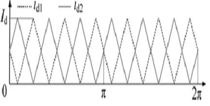
Fig. 3 shows the output currents id1 and id2.When the circulating current meets (1), the two diode bridge rectifiers operate under critical continuous conduction mode. If the amplitude of the circulating current is greater than the half of the load current, the diode bridge rectifiers operate under discontinuous conduction mode.
Fig. 3. Output currents of the two diode bridge rectifiers under critical continuous conduction mode In application, the grid frequency is viewed as a constant value.
EFFECT OF CIRCULATING CURRENT’S AMPLITUDE ON INPUT LINE CURRENT The three essential factors of the circulating current determine the harmonic elimination ability of the auxiliary circuit. If the circulating current does not meet the three essential factors, not only the harmonics are not
eliminated, but also the system may operate abnormally. Assume the expression of circulating current as
𝑖𝑝𝑥 1= 2𝛼𝑝𝐼𝑑 4
𝑛2𝜋2
∞
𝑛=1 sin 3𝑛𝜋
2 sin 6𝑛𝑤𝑡 (4) where αp describes the relation between the amplitude of circulating current and load current, and is defined as the ratio of amplitude of ipx1 to load current Id.
When αp is equal to 0.5, ipx1 is equal to ip. From (3), id1 and id2 are less than zero in some intervals if αp is >0.5. Hence, αp should meet
0 ≤ 𝛼𝑝≤1
2 (5) From Kirchhoff’s current law, the input line current of phase a can be expressed as
𝑖𝑎𝑥 1= 0.5𝐴1𝐼𝑑+ 𝐴2𝑖𝑝𝑥 1 (6) Where
𝐴1= 𝑆𝑎1+ 𝑆𝑎2+2− 3
3 𝑆𝑏1− 𝑆𝑐1+ 𝑆𝑐2− 𝑆𝑏2
𝐴2= 𝑆𝑎1− 𝑆𝑎2+2− 3
3 𝑆𝑏1− 𝑆𝑐1+ 𝑆𝑏2− 𝑆𝑐2
and Sa1, Sa2, Sb1, Sb2, Sc1 and Sc2 are the switching functions of phases a1, a2, b1, b2, c2 and c2, respectively.
𝑆𝑎1= 𝑖𝑑1
𝑖𝑎 1 (7) where id1 is the output current of rectifier I shown in Fig. 3. Fig. 4 illustrates the switching function Sa1.
Fig. 4. Switching function Sa1 The Fourier series expansion of Sa1 is calculated as
𝑆𝑎1= 4
(2𝑛−1) ∞
𝑛=1 cos (2𝑛−1)𝜋
6 sin 2𝑛 − 1 𝜔𝑡 +
𝜋
12 (8)
The switching functions of other phases meet
𝑆𝑏1= 𝑆𝑎1 < −2𝜋3
𝑆𝑐1= 𝑆𝑎1< + 2𝜋
3
𝑆𝑎2 = 𝑆𝑎1 < − 𝜋 6
𝑆𝑏2= 𝑆𝑏1−𝜋
6
𝑆𝑐2 = 𝑆𝑐1< −𝜋
6 (9)
From (6)–(9), the Fourier series expansion of iax1 can be calculated as
𝑖𝑎𝑥 1= 𝐼𝑑4 6 1−2𝛼𝑝
𝜋 3+1 sin 𝑤𝑡 +
sin 12𝑛±1 𝑤𝑡 (−1)𝑛 12𝑛±1
∞
𝑛=1 +
96 6𝛼𝑝𝐼𝑑sin 𝑤𝑡
𝜋2 3 3+5 +
96 6𝛼𝑝𝐼𝑑
𝜋2 3 3+5 ∞𝑛=1(−1) 24𝑛−1±1 /2 ×
sin 24𝑛±1 𝑤𝑡 (24𝑛±1)2 −
sin 24𝑛−12±11 𝑤𝑡
Hence, for the minimised THD of input line current, the optimal αp should be
𝛼𝑝=
(24(3 3−5) 𝑥+ 3−1 𝑧 𝜋
(24(3 3−5)
𝜋 2𝑥+𝑧 + 3−1 (2𝑧+𝑦)
≅ 0.4915 (11)
where x, y and z meet
𝑥 = ( 3−1)
12𝑛±1 2 ∞
𝑛=1
𝑦 = 24(3 3−5)
𝜋 12𝑛±1 2 2 ∞
𝑛=1
𝑧 = 48[(
1 24𝑛 −12±1)3−(
1 24𝑛 ±1 3]
−1 24𝑛 −11±
1
2 (7+4 3)𝜋
∞ 𝑛=1
(12)
In addition, from expression (11), we can draw the relation curve between the THD of input line current and αp, as shown in Fig. 5.
Fig. 5. Relation between THD of input line current and αp
(i) When αp is equal to zero, the THD is about 15.2%, and the MPR operates as 12-pulse rectifier. (ii) During the interval [0, 0.4915], the THD decreases as αp increases. When αp is about 0.4915, the THD is minimal. The minimum of THD is about 1.024%. (iii) During the interval [0.4915, 0.5], the THD increases as αp increases. When αp is equal to 0.5, the THD is about 1.06%.
(iv) Almost all previous results about the MPR with active IPR suggested that the amplitude of circulating current should be half of load current.
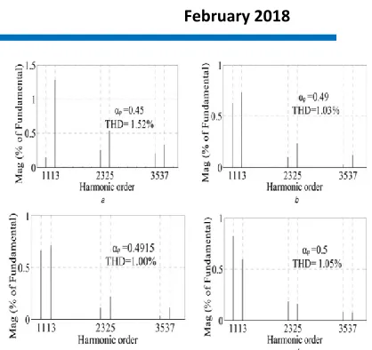
Fig. 6 shows the simulation results of input line currents’ spectrums under different αp. It is obvious that the input line current only contains a small quantity of characteristics harmonics when the active auxiliary circuit is utilized.
Fig. 6. Input line current and its spectrum under different αp a αp = 0.45 b αp = 0.49 c αp = 0.4915 d αp = 0.5 During the theoretical analysis, the leakage inductance of the autotransformer, the inductances of ZSBT and active IPR, are all ignored. Therefore, there is difference between the simulation results and theoretical results. Figs. 7a and b show the output currents of the two diode bridge rectifiers
(a)
(b)
Fig. 7. Output currents of diode bridge rectifier I and diode bridge rectifier II under different αp a αp = 0.5 b αp
= 0.4915
EFFECT OF CIRCULATING CURRENT’S PHASE ON INPUT LINE CURRENT
When analyzing the effect of circulating current’s phase on input line current, assume the expression of circulating current as
𝑖𝑝𝑥 2= 𝐼𝑑 4
𝑛2𝜋2sin
3𝑛𝜋
2 sin6n(𝜔𝑡 + 𝛽)
∞
𝑛=1 (13)
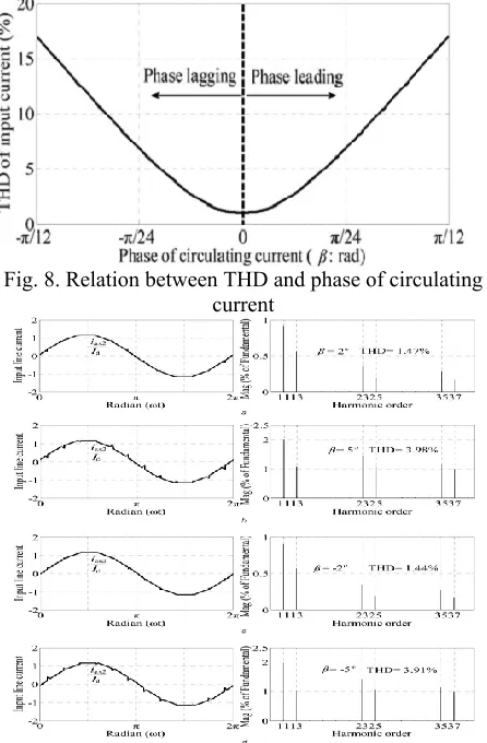
where β is the phase of ipx2. When β is less than zero, ipx2 lags the synchronous signal by β electrical degree. When β is greater than zero, ipx2 leads the synchronous signal by β electrical degree. The output line voltage of phase-shift transformer is always sampled to be the synchronous signal. When β is equal to zero, ipx2 is equal to ip. Generally, −π/12 ≤ β ≤ π/12. Similarly, the input line current of phase a can be expressed as
𝑖𝑎𝑥 2= 0.5𝐴1𝐼𝑑+ 𝐴2𝑖𝑝𝑥 2 (14) Fig. 8 shows the relation between THD and phase of circulating current. Fig. 9 shows the input line currents and their spectrums under different phases of circulating current. Therefore, both the circulating current lagging and leading the synchronous signal lead to the increase of harmonic amount in input line current.
Fig. 8. Relation between THD and phase of circulating current
Fig. 9. Input line currents and their spectrums under different phases of the circulating current
FUZZY LOGIC CONTROLLER
In FLC, basic control action is determined by a set of linguistic rules. These rules are determined by the system. Since the numerical variables are converted into linguistic variables, mathematical modeling of the system is not required in FC.
Fig.10.Fuzzy logic controller
The FLC comprises of three parts: fuzzification, interference engine and defuzzification. The FC is characterized as i. seven fuzzy sets for each input and output. ii. Triangular membership functions for simplicity. iii. Fuzzification using continuous universe of discourse. iv. Implication using Mamdani’s, ‘min’ operator. v. Defuzzification using the height method.
TABLE III: Fuzzy Rules
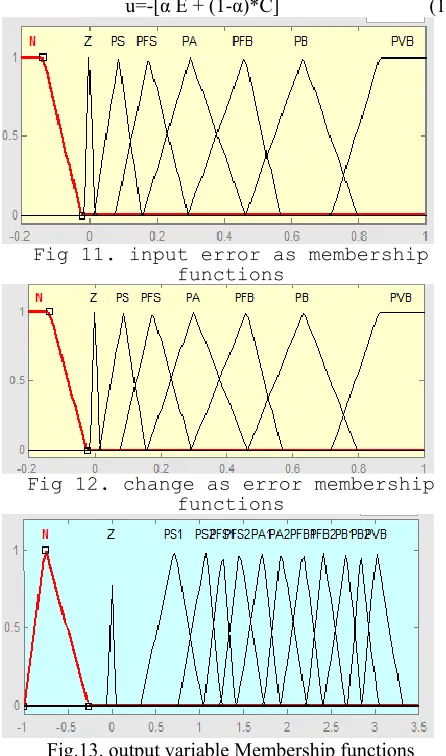
Fuzzification: Membership function values are assigned to the linguistic variables, using seven fuzzy subsets: NB (Negative Big), NM (Negative Medium), NS (Negative Small), ZE (Zero), PS (Positive Small), PM (Positive Medium), and PB (Positive Big). The value of input error and change in error are normalized by an input scaling factor.In this system the input scaling factor has been designed such that input values are between -1 and +1. The triangular shape of the membership function of this arrangement presumes that for any particular E(k) input there is only one dominant fuzzy subset. The input error for the FLC is given as
E(k) = Pp h (k )−Pp h (k −1)
Inference Method: Several composition methods such as Max–Min and Max-Dot have been proposed in the literature. In this paper Min method is used. The output membership function of each rule is given by the minimum operator and maximum operator. Defuzzification: As a plant usually requires a non-fuzzy value of control, a defuzzification stage is needed. To compute the output of the FLC, „height‟ method is used and the FLC output modifies the control output. Further, the output of FLC controls the switch in the inverter. In UPQC, the active power, reactive power, terminal voltage of the line and capacitor voltage are required to be maintained. The set of FC rules are derived from
u=-[α E + (1-α)*C] (17)
Fig 11. input error as membership functions
Fig 12. change as error membership functions
Fig.13. output variable Membership functions Where α is self-adjustable factor which can regulate the
whole operation. E is the error of the system, C is the change in error and u is the control variable
SIMULATION RESULTS
There are several topologies to realise the function of the auxiliary circuit. In this paper, we propose a two-stage auxiliary circuit which is the combination of PWM converter and boost converter, as shown in Fig. 10.
Fig. 14. Control block diagram of the proposed MPR with two-stage auxiliary circuit
Fig.15. Overview of the simulation block diagram
Fig.16.Control block diagram of simulation
load voltage. Table 1 shows the parameters of the MPR and auxiliary circuit for setup.
Table 1
Parameters of the MPR and auxiliary circuit
parameter Value
Load voltage 𝑈𝑑 242V
Load current 𝐼𝑑 6A
Turn ratio of active IPR 1:1 Front stage inductor 𝐿𝑎 1mH Front stage switching frequency 50KHZ
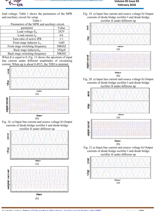
Back stage inductor𝐿𝑏 350𝜇𝐻 Back stage switching frequency 50KHZ When β is equal to 0, Fig. 12 shows the spectrum of input line current under different amplitudes of circulating current. When αp is about 0.4915, the THD is minimal.
(a)
(b)
Fig. 18. a) Input line current and source voltage b) Output currents of diode bridge rectifier I and diode bridge
rectifier II under different αp
(a)
(b)
Fig. 19. a) Input line current and source voltage b) Output currents of diode bridge rectifier I and diode bridge
rectifier II under different αp
(a)
(b)
Fig. 20. a) Input line current and source voltage b) Output currents of diode bridge rectifier I and diode bridge
rectifier II under different αp
(a)
(b)
Fig. 21.a) Input line current and source voltage b) Output currents of diode bridge rectifier I and diode bridge
rectifier II under different αp
(b)
Fig.22. a) Input line current and source voltage b) Output currents of diode bridge rectifier I and diode bridge
rectifier II under different αp
(a)
(b)
Fig.23. a) Input line current and source voltage b) Output currents of diode bridge rectifier I and diode bridge
rectifier II under different αp
(a)
(b)
Fig.24. a) Input line current and source voltage b) Output currents of diode bridge rectifier I and diode bridge
rectifier II under different αp
(a)
(b)
Fig.25. a) Input line current and source voltage b) Output currents of diode bridge rectifier I and diode bridge
rectifier II under different αp
In general, the THD variation trend in the results is coincident with that of theoretical analysis. When αp is equal to 0.4915 and the circulating current leads the synchronous signal by about 3.6 electrical degrees, Fig. 13 shows the spectrum of input line current. Therefore, the phase leading of circulating current leads to increase in THD of input line current. When the circulating current lags the synchronous signal, we also obtain the similar results.
CONCLUSION
According to the paper we are implementing the effect of the circulating current which is based upon the performance of the MPR with the active IPR. In the precious section which is explained that the amplitude of the circulating current will be usually equal to the half of the load current then the THD of the input line current will be minimum. Therefore in this paper we are developing the fuzzy controller for the better performance. Here the fuzzy controller is the most suitable for the human decision-making mechanism, providing the operation of an electronic system with decisions of experts. After fuzzy controller the THD of the inp205*ut current will be minimum when compare the amplitude which is slightly less than the half of the load current. By using the simulation results we can verify both the lagging and leading circulating current of the synchronous signals, which will leading to the minimize the harmonics in the input line current. Finally in this paper we can extend the other MPRs which are auxiliary circuit of the active harmonics reduction at the DC side.
REFERENCES
review’, IEEE Trans. Power Electron., 2008, 23, (1), pp. 260–281
2 Meng, F., Yang, W., Yang, S.: ‘Effect of voltage transformation ratio on the kilovoltampere rating of delta-connected autotransformer for 12-pulse rectifier system’, IEEE Trans. Ind. Electron., 2013, 60, (9), pp. 3579–3588
3 Carastro, F., Castellazzi, A., Clare, J., et al.: ‘High-efficiency high-reliability pulsed power converters for industrial processes’, IEEE Trans. Power Electron., 2012, 27, (1), pp. 37–45
4 Akagi, H., Isozaki, K.: ‘A hybrid active filter for a three-phase 12-pulse diode rectifier used as the front end of a medium-voltage motor drive’, IEEE Trans. Power Electron., 2012, 27, (1), pp. 69–77
5 Eid, A., EI-Kishky, H., Abdel-Salam, M., et al.: ‘On power quality of variable-speed constant-frequency aircraft electric power systems’, IEEE Trans. Power Deliv., 2010, 25, (1), pp. 55–65
6 Young, C.-M., Chen, M.-H., Lai, C.-H., et al.: ‘A novel active interphase transformer scheme to achieve three-phase line current balance for 24-pulse converter’, IEEE Trans. Power Electron., 2012, 27, (4), pp. 1719– 1731
7 Fernandes, R.C., da Silva Oliveira, P., de Seixas, F.J.M.: ‘A family of autoconnected transformers for 12- and 18-pulse converters-generalization for delta and wye topologies’, IEEE Trans. Power Electron., 2011, 26, (4), pp. 2065–2078
8 Choi, S., Enjeti, P.N., Lee, H.H., et al.: ‘A new active interphase reactor for 12-pulse rectifiers provides clean power utility interface’, IEEE Trans. Ind. Appl., 1996, 32, (6), pp. 1304–1311
9 Hamad, M.S., Masoud, M.I., Williams, B.W.: ‘Medium-voltage 12-pulse converter: output voltage harmonic compensation using a series APF’, IEEE Trans. Ind. Electron., 2014, 61, (1), pp. 43–52
10 Meng, F., Yang,W., Yang, S.: ‘Active harmonic suppression of paralleled 12-pulse rectifier at DC side’, Sci. China: Technol. Sci., 2011, 54, (12), pp. 3320–3331.
JADDU NAGA SUDEEP
Completed B.TECH in Electrical & Electronics Engineering in 2014 from Rajamahendri Institute of Engineering & Technology Affiliated to JNTUK, KAKINADA and Pursuing M.Tech form Kakinada Institute of Technological Sciences Affiliated to JNTUK
,KAKINADA, Andhra Pradesh, India. Area of interest includes High Voltage Engineering.
E-mail id: [email protected].
RAMA KRISHNA PERLA
Completed B.Tech in Electrical &Electronics Engineering in 2013 from Swarnandhra College of Engineering and Technology Affiliated to JNTUK, Kakinada and M.Tech in Power Industrial Drives in 2015from DADI Institute of Engineering and Technology Affiliated to JNTUK, Kakinada. Working as Assistant Professor at Kakinada Institute of Technological Sciences, Kakinada, Andhra Pradesh, India. Area of interest includes Power electronics.