Available online: https://edupediapublications.org/journals/index.php/IJR/ P a g e | 3081
A Novel High step-up dc–dc converter for Boosting Fuel Cell Voltage
through the Three-Winding Coupled Inductor
Alle Siva Prasad &
K.Chandra Sekhar
1M.Tech Student, Dept. of EEE, INTELL Engineering College, Affiliated to JNTUA , Andhra Pradesh, India
2Assistant Professor in Dept. of EEE, , INTELL Engineering College, Affiliated to JNTUA, Andhra Pradesh, India
ABSTRACT:
The main objective of this paper is to design and implement a novel a high step-up dc–dc converter which is devised for boosting the voltage generated from fuel cell through the three-winding coupled inductor and voltage doubler circuit, the proposed converter achieve high step-up voltage gain without large duty cycle. The main advantages of the proposed converter are simple topology, high step-up voltage gain, continuous input current, recycling the energy of the leakage inductance of the coupled inductor, and utilizing only one active switch with reduced voltage stress. Reduced switch voltage stress results in selection of switch with low on-resistance which improves the efficiency. Operational principles of the converter in steady state are studied and an analytical approach is used to attain voltage gain and switch voltage stress. Finally appropriate performance of the proposed topology is verified by simulation.
I. INTRODUCTION
In the present world electrical energy is necessary to meet several needs and is generated by numerous sources like coal, nuclear energy, water, wind etc. The above methods which are used for the power generation are having many drawbacks. The cost of generation is high and it is difficult to serve the electricity in the remote areas where the transmission and distribution system does not exist. Energy demand is increasing day to day. But our fossil fuel deposits are also decreasing day to day. Unfortunately greater than 70% of our energy needs is met by thermal power plants only. So, alternative sources for the production of electricity are preferred. There exists renewable energy resources like
solar, wind energy etc which are available at free of cost, but they are not reliable because of they are irregular in nature. Many researches are there regarding fuel cells as these are preferred by the researchers as one of the most promising power supply source in the future. Fuel cell are having high efficiency and stability, low energy consumed and no pollution to the environment, this technology is in the progress to commercialize. Fuel cell has an additional advantage of utilizing hydrogen as fuel that will reduces the world dependence on non-renewable hydrocarbon resources . A Fuel Cell electric Vehicles has higher efficiency and lower pollutant emissions compared with the internal combustion engine vehicles. So, FCEV provides a much better performance.
The fuel cell with inertia characteristics as main power source cannot respond to load dynamics well. Therefore, lithium iron phosphate can be an excellent candidate for secondary source to react to fast dynamics and contribute to load peaking. The proposed converter with fuel cell input source is suitable to operate in continuous conduction mode (CCM) because the discontinuous conduction mode operation results in large input current ripple and high peak current, which make the fuel cell stacks difficult to afford.
II. LITERATURE SURVEY
Available online: https://edupediapublications.org/journals/index.php/IJR/ P a g e | 3082 to improve the output voltage of the fuel cell. The
step-up gain of a conventional boost converter is restricted by the effect of power switch, resistance of inductors and conduction losses due to extreme duty cycle. So, the boost converter can be operated in fly back mode of operation in which an isolation is given between the primary and secondary. Here zero voltage switching and zero current switching modes are preferable to achieve high efficiency. Introducing coupled inductor technology is also an enhancement to improve the performance of converter. The coupled inductor technology can be replaced by Multi-winding transformer to achieving achieve high voltage gains and improve the converter efficiency. Commonly, a lot of low-voltage cells are integrated to a fuel-cell stack to improve the output power level. The output voltage of the fuel-cell stack is lower than 40 V due to the cost and reliability issues in the household stand-alone power generation applications. This means that a front-end dc/dc converter is necessary to boost the low voltage of the fuel-cell stack to a standard high bus voltage before being inverted into a 440-V dc output. The required dc/dc converter should have the advantages of large voltage-conversion ratio, high efficiency, and small input-current ripple. The widely employed isolated voltage-fed converters are not the optimal candidates for the high-step-up fuel-cell generation system because they have a step-down conversion feature, large input-current ripple, and high output-diode voltage stress. The large transformer turns ratio, an additional LC input filter, and the heavy output-diode losses are the main obstacles for their efficiency and power density improvements. Compared with the voltage-fed converters, the isolated current fed converters have the clear advantages of input-current-ripple reduction and high-step-up voltage ratio in the low-input high output-voltage conversion system. The conventional current-fed push–pull converters are welcomed in the high-step-up and low-power applications due to their simple circuit and flexible flux balance for the transformer. Furthermore, some improvements have been made to realize a soft-switching presentation. However, the voltage stress of
the primary switches is comparatively high. The current- fed full-bridge converters are suitable for the large current applications. The dual boost converters can distribute the input current due to the interleaved operation. In addition, the active-clamp circuits can be inserted to achieve a zero voltage-switching (ZVS) soft-switching performance and to recycle the leakage energy. Unfortunately, there are two input inductors and one transformer in the dual boost converters, which limits the power density improvements. Unfortunately, the duty cycle of the primary main switches should be larger than 0.5 because a current path should be provided for the input inductor in any operation condition. Therefore, an additional start-up solution should be deliberate to reduce the inrush current during the start-up operation. Some interleaved boost converters with winding cross-coupled inductors and active-clamp circuits are proposed for large-current and high-output-voltage conversion. In this paper, a high-step-up interleaved flyback–forward converter with active-clamp circuits is proposed for the household fuel-cell power-generation system. Boost-type conversion is realized by employing two coupled inductors to obtain alarge voltage conversion ratio, where each coupled inductor can work in the flyback mode when the corresponding main switch is in the turn-on state and in the forward mode when it is in the turnoff state. As a result, the magnetic core is fully utilized and the power density is enhanced. Furthermore, by introducing the active-clamp scheme, a ZVS soft-switching operation is carried out for the primary main and clamp switches. The diode reverse-recovery problem is alleviated for the secondary rectifier diodes. Hence, the power-device switching losses are reduced to improve the circuit efficiency. Moreover, the input current is distributed and the input-current ripple is minimized by the interleaved operation and the current-fed configuration. All the aforementioned distinguished features make the proposed converter an optimal candidate for the high-step-up, high-efficiency, and high-power-density conversion.
III. PROPOSED SYSTEM
Available online: https://edupediapublications.org/journals/index.php/IJR/ P a g e | 3083 The switched capacitor supplies an extra step-up
performance; the voltage-doubler circuit lifts of the output voltage by increasing the turns ratio of coupled-inductor.
The advantages of proposed converter are as follows: 1) through adjusting the turns ratio of coupled inductor, the proposed converter achieves high step-up gain that renewable energy systems require;
2) leakage energy is recycled to the output terminal, which improves the efficiency and alleviates large voltage spikes across the main switch;
3) due to the passive lossless clamped performance, the voltage stress across main switch is substantially lower than the output voltage;
4) low cost and high efficiency are achieved by adopting low-voltage-rated power switch with low RDS-ON; 5) by using three-winding coupled inductor, the proposed converter possesses more flexible adjustment of voltage conversion ratio and voltage stress on each diode.
IV. IMPLEMENTATION
Fig.1 Single line diagram of multi winding transformer based fly back converter.
OPERATING PRINCIPLE
The equivalent circuit of the proposed converter shown in Fig. 1 is composed of a coupled inductor Tr, a main power switch S, diodes D1,D2,D3, and D4, the switched capacitor Cb, and the output filter capacitors C1,C2, andC3. Lm is the magnetizing inductor andLk1,Lk2,
andLk3represent the leakage inductors. The turns ratio of coupled inductor n2 is equal toN2/N1, andn3is equal toN3/N1, whereN1,N2, and N3 are the winding turns of coupled inductor.
Mode I [t0,t1]:During this interval, the switch S is turned ON at t0. The diodes D1,D2, andD4 are reverse biased. The path of current flow is shown in Fig. 5(a). The primary leakage inductor current iLk1 increases linearly, and the energy stored in magnetizing inductance still transfers to the load and output capacitorC2via diodeD3.
Mode II [t1,t2]:During this interval, the switch S is still in the turn-on state. The diodesD1andD4are forward biased; diodes D2andD3are reverse biased. The dc source Vin still charges into the magnetizing inductor Lm and leakage inductor Lk1, and the currents through these inductors rise linearly. Some of the energy from dc source Vin transfer to the secondary side of the coupled inductor to charge the capacitorC3. The switched capacitor Cb is charged by the LC series circuit.
Mode III [t2,t3]: During this interval, the switch S is turned OFF at t2. DiodesD1and D4 are still forward biased; diodesD2 and D3are reverse biased. The magnetizing current and LC series current charge
the parasitic capacitor Co of the MOSFET.
Mode IV [t3,t4]: During this interval, S is still in the turnoff state. The diodes D1,D2, and D4 are forward biased. The diode D3 is reverse biased. The current id4 charges the output capacitor C3 and decreases linearly. The total voltage of Vin+VLm+VCb is charging to clamped capacitorC1, and some of the energy is supplied to the load.
Mode V [t4,t5]: During this interval, switch S is still in the turn-off state. The diodesD1andD4are turned OFF; the diodes D2 andD3 are forward biased. The energy of
the primary side still charges to the clamped capacitorC1and supplies energy to the load. Some of the energy from dc source Vin is transferred to the secondary side of the coupled inductor to charge the capacitorC2, and the currentid3increases linearly.
Available online: https://edupediapublications.org/journals/index.php/IJR/ P a g e | 3084
Fig.3 Output voltage waveform of the proposed converter
Fig.3 shows the output voltage waveform of the in
which the steady state output voltage is 440 volts
which is obtained from 60V input fuel cell. The
wave form has low ripple content and the
corresponding current waveform is given below
Fig.4 Output current waveform
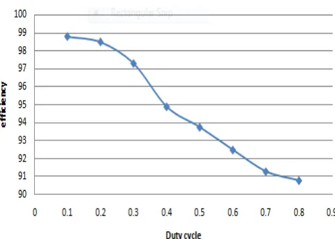
The corresponding graphs for various values of duty cycle are given below.
Fig 5 Duty cycle Vs efficiency for multi winding transformer based converter.
Fig.6. Duty cycle Vs voltage gain for multi winding
transformer based converter
Available online: https://edupediapublications.org/journals/index.php/IJR/ P a g e | 3085 The voltage gain conversion efficiency of the proposed
converter is more than the coupled inductor based step-up converter. The voltage gain is high for the proposed converter, so the proposed converter is suitable for a low voltage source to grid connection. Similarly, the output current of the proposed converter is desired value. As compared to other converter, the proposed converter has improved output voltage, output power and efficiency.
VII. CONCLUSION
In this project, a high step-up dc–dc converter for fuel cell hydroid electric vehicle applications is clearly analyzed and successfully verified by employing technologies of three-winding coupled inductor, switched capacitor, and voltage doubler circuit, the high step-up conversion will be efficiently obtained. The leakage energy is recycled and large voltage spike is alleviated; thus, the voltage stress is limited and also the efficiency is improved. The full-load efficiency is up to 91.32% and also the maximum efficiency is up to 96.81%. The voltage stress on the main switch is clamped as 120 V at Dmax . The low-voltage-rated switch with low RD S -O N will be chosen for the reduction of conduction losses. Thus, the proposed device is suitable for high-power applications as fuel cell systems in hydroid electric vehicles.
REFERENCES
[1 ] S. Jemei, D. Hissel, M. C. Pera, and J. M. Kauffmann, “A new model ing approach of embedded fuel-cell power generator based on artificial neural network,” IEEE Trans. Ind. Electron., vol. 55, no. 1, pp. 437–447, Jan. 2008.
[2] M. H. Todorovic, L. Palma, and P. N. Enjeti, “Design of a wide input range dc–dc converter with a robust power control scheme suitable for fuel cell power conversion,” IEEE Trans. Ind. Electron.,
vol. 55, no. 3, pp. 1247–1255, Mar. 2008.
[3] K. Jin, M. Yang, X. Ruan, and M. Xu, “Three-level bidirectional converter for fuel-cell/battery hybrid power system,” IEEE Trans. Ind. Electron., vol. 57, no. 6, pp. 1976– 1986, Jun. 2010.
[4] C. T. Pan and C. M. Lai, “A high-efficiency high step- up converter with low switch voltage stress for fuel-cell system applications,” IEEE Trans.Power Electron., vol. 57, no. 6, pp. 1998–2006, Jun. 2010.
[5] E. H. Kim and B. H. Kwon, “Zero-voltage- and zero- current-switching full-bridge converter with secondary resonance,” IEEE Trans. Ind. Electron., vol. 57, no. 3, pp. 1017–1025, Mar. 2010.
[6] F. Liu, J. Yan, and X. Ruan, “Zero-voltage and zero- current-switching PWM combined three-level dc/dc converter,” IEEE Trans Ind. Electron., vol. 57, no. 5, pp. 1644–1654, May 2010.
[7] Y. Jang and M. M. Jovanovic, “A new three-level soft- switched converter,” IEEE Trans. Power Electron., vol. 20, no. 1, pp. 75–81, Jan. 2005.
[8] Y. Jang and M. M. Jovanovic, “A new family of full- bridge ZVS converters,” IEEE Trans. Power Electron., vol. 19, no. 3, pp. 701–708, May 2004.