www.ijiset.com
94
Human Action Recognition using Spatio-Temporal Features
from Kinect Petar Nikolov
Petar Nikolov,
PhD student from Technical University of Sofia
Abstract: This paper presents a person - motion analysis method by using the information provided by Microsoft’s Kinect sensor. Described are the Kinect’s raw data type, movement vector calculation and the data analysis used to compare the current data to the one determined beforehand for each defined action or the one dynamically calculated.
Keywords: Motion, analysis, Kinect
1. Introduction
Motion analysis is a topic related with computer vision – a subject of a deep research work in the recent years. The applications of such systems, capable to distinguish the human activities, are endless. Systems for security and video surveillance, personal assistants or other systems for human-machine interactions.
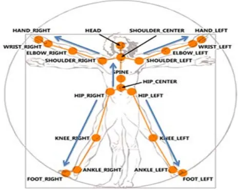
The human body consists of a set of non folding parts, connected with joints and a human motion could be represented like a continuous change of their positions [1]. The proposed method is using the joint positions to represent the poses of a human body. Microsoft Kinect sensor is providing a color image along with the labeled data of each joint of up to 6 persons. The second version of Kinect is providing the information of the positions of a 25 points of the human body (Fig.1).
The described algorithm aims to determine a position-invariant human activity in terms of a distance between the body and the sensor.
2. Proposed method description
Using of a color images for joint model description, which is known as “skeleton” requires a high computational power and is a prerequisite of a presence of a high amount of mistakes. Using the Kinect sensor, we acquire the body stance and joint positions with high accuracy. The proposed method offers a simplified representation of a body posture, based on the joint location in the depth map provided by the sensor.
The workflow of the algorithm could be separated in to two main stages – recording a sequence of motion vectors and
comparing the resultant motion vector to classify human motion.
Fig. 1: 25 joints of a human body, provided by Kinect sensor
2.1 Tracking
In each frame, each point of interest is defined as:
𝐹⃗
= [
𝑥
,
𝑦
,
𝑑𝑖𝑠𝑡𝑎𝑛𝑐𝑒
,
𝑎𝑛𝑔𝑙𝑒
],
where:
𝐹⃗ – intrinsic vector of a point of interest;
𝑥– x coordinate of a point of interest;
y – y coordinate of a point of interest;
distance – distance between the points of interests
angle – angle between the locations of the points of interest in the current and the previous frame.
www.ijiset.com
95
work correctly, before beginning the recording, we have toinitialize the algorithm with N frames received from the sensor. This is necessary in order to determine the exact center of the coordinate system which would be used in motion vectors calculation On determining the vector direction, the center of the coordinate system is the point of interest N frames before the beginning of recording This leads to displacement of the center in each arrived frame. The maximum angel error is 15° - when are defined М = 24 displacements zone.
Once we have the information about the position of the points of interest, each of them is processed with a linear regression. This step is required due to the noise introduced in our measurements and in the data we receive from the sensor. Linear regression is using the following calculations: (Fig. 2):
Fig. 2: Linear regression
(1)
𝑎
=
𝑦� − 𝑏𝑥̅
(2)
𝑏
=
∑ 𝑥𝑦−𝑛𝑥𝑦���� ∑ 𝑥2−𝑛𝑥̅2where:
𝑥̅= ∑ 𝑥𝑛 - mean value of coordinate х
𝑦�= ∑ 𝑦𝑛 - mean value of coordinate y
𝑥𝑦
���=∑(𝑛𝑥𝑦) – mean value of the product of the two coordinates
𝑛– number of points used for regression calculation
In formula (1) parameter а represent the offset of the regression line to the x axys. If х=0, then y=а.
Parameter b represents the slope of that line. Using regression line calculation we can calculate the displacement error for each point of interest compared to the pervious frames. In longer records this realization would lead to a delay in the
operation of the algorithm, because with each frame the points which considered to determine the straight line increase. To determine the recalculated location of the point of interest is used:
(3)
𝑦�
=
𝑎
+
𝑏𝑥
where 𝑦� is recalculated value of у and 𝑥 e х- value of the original coordinates of the point of interest.
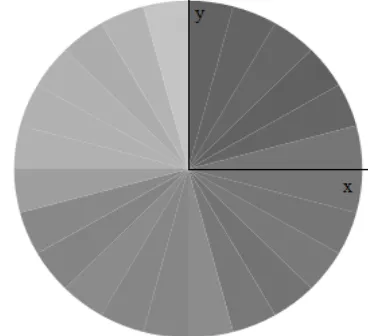
For initial initialization of the parameters are chosen zero values. Then the vector is represented in a coordinate system, divided into M equal-sized segments to determine which direction is movement (Figure 3). These sectors divide the space of M possible directions of motion. If the position of the point of interest is located in a sector other than previous to that point of interest, it creates resultant vector.
Fig. 3: Sectors used for analyzing the direction of the motion
vector.
Due to the sensor imperfections, the obtained data do not always correspond to the real data. If the movement takes place near the border between two sectors, even minor deviation could lead to displacement of the point from one sector to another. This would imply that new motion vector is created. In order to avoid the creation of new motion vectors, vector differences are compared with predefined thresholds.
If the difference is less than the threshold, then the resultant vector is combined with the previous motion vector according to Triangle law of vector addition to form a completely new motion vector in place of the old one.
For the creation of the new motion vector is used the direction determined in the previous step and the length, which is equal to the distance between the two points.
www.ijiset.com
96
This mode is similar to the preceding, on manner in whichcalculates vectors and describes movement. Obtaining new frame, the positions of all points of interests are calculated. Each of them is processed individually. The direction of the resultant vector is also calculated and a decision is taken whether it is necessary to create a new vector or the resultant vector should be merged with the one from the previous frame. For the purpose of comparing motions, the vector obtained in the processing of a new frame is compared by its length and direction with all the vectors stored during the recording of movement.
If the initial point A is known with coordinates АRх Randy АRу R
and the final point B with coordinates BRх Rand BRу Ris also
known, then the distance r between them could be calculated using:
(4)
е
=
�
(
А
х− Б
х)
2+
�А
у− Б
у�
2For the angle calculation, the possible variations are: • ∆х = ∆у = 0, α = 0 °
• ∆х = 0 и ∆у > 0, α = 270° • ∆х = 0 и ∆у < 0, α = 90° • ∆х > 0 и ∆у = 0, α = 180° • ∆х < 0 и ∆у = 0, α = 0°
• ∆х > 0 и ∆у < 0, ∝ = 90 + tan−1�∆𝑥
∆𝑦� ∗180/𝜋
• ∆х < 0 и ∆у > 0, ∝ = 270 + tan−1�∆𝑥
∆𝑦� ∗180/𝜋
• ∆х < 0 и ∆у < 0, ∝ = tan−1�∆𝑥
∆𝑦� ∗180/𝜋
• ∆х > 0 и ∆у > 0, ∝ = 180 + tan−1�∆𝑥
∆𝑦� ∗180/𝜋
Where ∆х is the first difference in (4) and ∆у is the second one, α is the angle of interest.
If the calculated vector in the current frame has a direction match but not a length match, the vector is not considered for further calculations. The same consideration is valid also if there is a length match but not a direction one. The only option for two vectors to be considered equal is that both the direction and the distance are the same. This is valid under the condition that distance and directions matchings are done compared to a specified thresholds.
The decision about the vector recognition is done using :
�𝑠𝑎𝑣𝑒𝑑𝑗𝑖(𝑎𝑛𝑔𝑙𝑒)− 𝑐𝑢𝑟𝑟𝑗(𝑎𝑛𝑔𝑙𝑒)�<𝑎𝑛𝑔𝑙𝑒𝑇ℎ𝑟𝑒𝑠ℎ𝑜𝑙𝑑
∩
�𝑠𝑎𝑣𝑒𝑑𝑗𝑖(𝑑𝑖𝑠𝑡𝑎𝑛𝑐𝑒)− 𝑐𝑢𝑟𝑟𝑗(𝑑𝑖𝑠𝑡𝑎𝑛𝑐𝑒)�<𝑎𝑛𝑔𝑙𝑒𝑇ℎ𝑟𝑒𝑠ℎ𝑜𝑙𝑑
Where:
j – index representing the point of interest; i – index of the recorded resultant vector; angle – the angle of the correspondent vector; distance – the length of the correspondent vector;
currRjR – resultant vector between the current and the previous
frame for the j-th point of interest;
savedRji R– the i-th recorded vector for the j-th point of interst;
To be recognized, the vector must meet both conditions. In order for the algorithm to be invariant of the position of the body in front of the sensor, in the above formula should be inserted a distance correction. During recording of the motion, a average distance of each of the points of interest to the sensor is stored. Kinect automatically provides distance information to the relevant points. After recording the average values are preserved. In order to be correctly used this information we receive from the sensor, we must comply with its specifications - working range of the body must be at least 1.37 meters and no further than 6m. In detection mode for each point of interest is measured coefficient, which is the ratio of the distance to the sensor in the current frame to the average distance to the sensor for the same point of interest during recording of motion.
3. Results of the experiment
www.ijiset.com
97
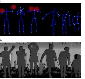
а)б)
Fig 4: a) Skeleton data for each of the points of interest for the six selected movements. b) depth maps of selected activities.
The accuracy of identification of the different movements varies in thresholds 74-80%
Table 1: Maximum accuracy achieved in recognition of relevant activity
Two of the key parameters in the algorithm are based on minimum error that caused in various activities.
• angleDiff – threshold for joining consecutive vectors;
• numberOfAngleDetectionZones – number of zones defining the change in the direction of movement;
The first parameter – threshold for resultant vector initialization in adjacent frames. The threshold should always be less than
360/ number of zones for motion detection. The provided results are achieved using the Kinect sensor at a distance of 2.5m.
Table2: Results on determining the angle threshold.
Second parameter - the number of areas for motion detection - determining of how many zones will be divided coordinate system .
Table 3: Results in the determination of "number of zones for determining the angle of the motion vector"
4. Conclusion
In this paper we proposed a method for motion recognition using a skeleton data provided by the Microsoft’s RGB-D sensor Kinect. The system is able to classify a motion performed from a person among multiple stored motion descriptions in a database. From the conducted experiments, the classification rate vary between 76% and 80%. The current system can be extended by including more skeleton points for tracking or by using additional Kinect sensors.
Acknowledgement: This paper was supported by Technical University – Sofia inner program to support PhD research projects under Contract № 162pd0025-7: “Human action estimation based on video image analysis”
References
www.ijiset.com
98
Applications”, The 7th International Conference on InformationTechnology (ICIT’ 2015), pp. 577-585, 2015.
[2] Kavita V. Bhaltilak, Harleen Kaur, Cherry Khosla, "Human Motion Analysis with the Help of Video Surveillance: A Review," In the International Journal of Computer Science Engineering and Technology (IJCSET), Volume 4, Issue 9, pp. 245-249,2014.
[3] Chen Change Loy, "Activity Understanding and Unusual Event Detection in Surveillance Videos," PhD dissertation, Queen Mary University of London, 2010.
[4] Mao Ye, Qing Zhang, Liang Wang, Jiejie Zhu, Ruigang Yang, Juergen Gall, "A Survey on Human Motion Analysis from Depth Data," Lecture Notes in Computer Science, Springer, Vol. 8200, pp 149-187, 2013.
[5] Lulu Chen, Hong Wei, James Ferryman, "A survey of human motion analysis using depth imagery," In Pattern Recognition Letters, Elsevier Science Inc., Volume 34, pp. 1995-2006, 2013.
[6] Maaike Johanna, "Recognizing activities with the Kinect," Master thesis, Radboud University Nijmegen, Nijmegen, Netherlands, 2013. [7] Ferda Ofli, Rizwan Chaudhry, Gregorij Kurillo, René Vidal, and Ruzena Bajcsy, "Sequence of the Most Informative Joints (SMIJ): A New Representation for Human Skeletal Action Recognition," In proceedings of the IEEE Computer Vision and Pattern Recognition Workshops (CVPRW), Providence, Rhode Island, USA, PP. 8-13, 2012.
[8] Ahmad Jalal, Shaharyar Kamal and Daijin Kim, "A Depth Video Sensor-Based Life-Logging Human Activity Recognition System for Elderly Care in Smart Indoor Environments," In the International Journal of Sensors, Volume 14, Number 7, pp. 11735-11759, 2014. [9] Samuele Gasparrini, Enea Cippitelli, Susanna Spinsante and Ennio Gambi, "A Depth-Based Fall Detection System Using a Kinect Sensor," In the International Journal of Sensors, Volume 14, Issue 2, pp. 2756-2775, 2014.
[10] Salah Althloothia, Mohammad H. Mahoora, Xiao Zhanga, Richard M. Voylesb, "Human Activity Recognition Using Multi-Features and Multiple Kernel Learning," In Pattern Recognition Journal, Volume 47, Issue 5, pp. 1800–1812, May 2014.
[11] Jiang Wang, Zicheng Liu, Ying Wu, Junsong Yuan, "Mining Actionlet Ensemble for Action Recognition with Depth Cameras," In Proceedings of the International IEEE Conference on Computer Vision and Pattern Recognition (CVPR), Providence, Rhode Island, USA, pp. 1290-1297, June 2012. [12] Adnan Farooq and Chee Sun Won, A Survey of Human Action Recognition Approaches that use an RGB-D
Sensor, IEIE Trans. on Smart Processing and Computing, vol. 4, no. 4, pp. 281-290, 2015
[13] J. Yamato, J. Ohya, and K. Ishii. Recognizing human action in timesequential images using hidden markov model. In CVPR, pp. 379–385, 1992.
[14] Alina Roitberg, Alexander Perzylo, Nikhil Somani, Manuel Giuliani, Markus Rickert, and Alois Knoll, “Human Activity Recognition in the Context of Industrial Human-Robot Interaction”, Asia-Pacific Signal and Information Processing Association, 2014 Annual Summit and Conference (APSIPA)
[15] Jaeyong Sung, Colin Ponce, Bart Selman, and Ashutosh Saxena. Human activity detection from RGBD images. CoRR, abs/1107.0169, 2011.
[16] Jaeyong Sung, Colin Ponce, Bart Selman, and Ashutosh Saxena. Unstructured human activity detection from RGBD images, IEEE International Conference on Robotics and Automation (A preliminary version of this work was presented at AAAI workshop on Pattern, Activity and Intent Recognition, 2011), pp. 842-849, 2014.
[17] Hema Swetha Koppula, Rudhir Gupta, and Ashutosh Saxena. Learning human activities and object affordances from rgb-d videos. The Intern. Journal of Robotics Research, pp. 951–970, 2013.
[18] Hema Koppula and Ashutosh Saxena. Learning spatio-temporal structure from rgb-d videos for human activity detection and anticipation. In Proceedings of the 30th International Conference on Machine Learning (ICML-13), pages 792–800, 2013.
[19] Brian Gleeson, Karon MacLean, Amir Haddadi, Elizabeth Croft, and Javier Alcazar. Gestures for industry: Intuitive human robot communication from human observation. In Proceedings of the 8th ACM/IEEE International Conference on Human-robot Interaction, HRI ’13, pages 349–356, 2013.
[20] Jaeyong Sung, Colin Ponce, Bart Selman, and Ashutosh Saxena. Human activity detection from RGBD images. CoRR, abs/1107.0169, 2011.
[21] L. Xia et al., “View invariant human action recognition using histograms of 3d joints,” Computer Vision and Pattern Recognition, IEEE Computer Society Conference on, pp. 20-27, 2012.