COMMUNICATION INTERFACE SPECIFICATION
NEC America, Inc.
NDA-30115-001
Revision 1.0
NEC America reserves the right to change the specifications, functions, or features in this document at any time without notice. NEC America has prepared this document for use by its employees and customers. The information contained herein is the property of NEC America and shall not be reproduced without prior written approval from NEC America.
Copyright 1999
TABLE OF CONTENTS
Page
Chapter 1 - Overview . . . 1
Chapter 2 - Architecture . . . 3
Asynchronous Transmission. . . 4
Line Control Characteristics . . . 4
Transmission Protocol . . . 5
Transmission Sequence . . . 7
From the NEAX to the PMS . . . 8
From the PMS to the NEAX . . . 9
Timers . . . 10
Sender Timer . . . 10
Receiver Timer . . . 10
Cabling Considerations . . . 10
Bisynchronous (BSC) Transmission . . . 10
Line Control Characteristics . . . 10
Transmission Protocol . . . 13
Transmission Sequence . . . . 15
Timers and Counters . . . 17
Retransmission Counts . . . 17
Timer Values . . . 17
Cabling Considerations . . . 18
Chapter 3 - Message Descriptions . . . 19
Data Link Maintenance . . . 19
Data Link Failure . . . 20
Release for Maintenance . . . 21
NEAX Operations During Loss of Communication . . . 21
Recovery from Loss of Communication . . . 21
Maid Status . . . 22
Message Waiting Lamp Control . . . 23
Restriction Control . . . 23
Check In/Check Out (Model 60) . . . . 23
Check In/Check Out (Model 90) . . . . 24
Wake Up/Group Announcement . . . 25
Room Move/Swap/Copy (Model 60) . . . 25
Room Data Change . . . 26
Extension Report . . . 26
Room Recovery (Model 60) . . . 27
Room Recovery (Model 90) . . . 28
Direct Data Entry (Model 90) . . . 28
Extension Connection . . . 29
Chapter 4 - Message Formats. . . 31
Data Link Maintenance . . . 32
Maid Status . . . 33
Cleaning . . . 34
Guest Room . . . 35
Page
Administration . . . 37
Message Waiting Lamp Control . . . 38
MWL Control . . . 38
MWL Status . . . 39
Restriction Control . . . 40
Check In/Check Out (Model 60) . . . 41
Check In 1 . . . 41
Check Out . . . 42
Check Out Message Report. . . 42
Check In 2 . . . 43
Check In 3 . . . 44
Check Out Outgoing Call Report . . . 45
Check Out Message Waiting Report . . . 45
Check In/Check Out (Model 90) . . . 46
Check In. . . 46
Check Out . . . 48
Check In Cancellation . . . 49
Check Out Cancellation . . . 49
Room Change . . . 50
Provisional Check In . . . 51
Provisional Check Out . . . 52
Check Out Message Waiting Report . . . 52
Wake Up/Group Announcement . . . 53
Wake Up Setting (NEAX). . . . 53
Wake Up Cancellation (NEAX) . . . 54
Wake Up Execution Result . . . 55
Wake Up Setting (PMS). . . 56
Wake Up Cancellation (PMS) . . . 57
Group Announcement Setting (NEAX) . . . 58
Group Announcement Cancellation (NEAX) . . . 59
Group Announcement Execution Result . . . 60
Group Announcement Setting (PMS) . . . 61
Group Announcement Cancellation (PMS) . . . 62
Room Move/Swap/Copy (Model 60) . . . 63
Room Data Change . . . 64
Room Data Change 60 . . . . 64
Group Formation . . . 65
Group Cancellation . . . 66
Reservation Setting . . . 66
Reservation Cancellation . . . 66
Guest Name Change . . . 67
Room Data Change 90 . . . . 67
Room Status Change. . . 69
Room Key Status Change . . . 70
Extension Report . . . 70
Extension Delete Report . . . 70
Extension Assignment Report . . . 71
Room Recovery (Model 60) . . . 72
Room Image Set 1 . . . 73
Room Image Set 2 . . . 74
Page
Room Recovery (Model 90) . . . 78
Room Data Report . . . 78
Guest Room Secretary Telephone . . . 80
Connecting Room . . . 80
Message Status Report . . . 81
Wake Up . . . 82
Direct Data Entry (Model 90) . . . 82
Direct Data Entry . . . 83
Direct Data Entry Answer. . . 83
Extension Connection . . . 84
Guest Room Secretary Telephone . . . 84
Connecting Room Set . . . 85
Connecting Room Cancel . . . 85
Chapter 5 - References . . . 87
Chapter 6 - Glossary . . . 89
Appendix A - Room Status . . . A1
Updating Room Status Information in the NEAX . . . A2 Clearing Room Data . . . A2 Dial Steps for Maid Status . . . A2 Room Status and Cleaning Status . . . A3 Status of Check Out . . . A3 Room Data Setting and Clearing in the NEAX . . . A3Appendix B - PMS Line Failure Printouts . . . B1
Normal Text . . . B1 Abnormal Events. . . B2 Abnormal Port . . . B2 Transmission Failure. . . B5Appendix C - Feature Codes. . . C1
LIST OF FIGURES
Figure Title Page
2-1 Start Sequence . . . 5
2-2 NEAX to PMS Protocol . . . 8
2-3 PMS to NEAX protocol . . . 9
2-4 Direct Connection Pin Assignments . . . 10
2-5 Base Message Format . . . 13
2-6 Message Data Format. . . 13
2-7 Direct Connection Pin Assignments . . . 18
4-1 Base Message Format . . . 31
4-2 Data Link Maintenance Message Format . . . 33
4-3 Cleaning (General) . . . 34
4-4 Guest Room (General) . . . 35
4-5 Room Answer (General) . . . 36
4-6 Administration (General) . . . 37
4-7 MWL Control (General) . . . 38
4-8 MWL Status. . . 39
4-9 Restriction Control. . . 40
4-10 Check In 1 . . . 41
4-11 Check Out . . . 42
4-12 Check Out Message Waiting Lamp Report . . . 42
4-13 Check In 2 . . . 43
4-14 Check In 3 . . . 44
4-15 Check Out Outgoing Call Report. . . 45
4-16 Check Out . . . 45
4-17 Check In . . . 46
4-18 Check Out . . . 48
4-19 Check In Cancellation . . . 49
4-20 Check Out Cancellation. . . 49
4-21 Room Change . . . 50
4-22 Provisional Check In . . . 51
4-23 Provisional Check out . . . 52
4-24 Check Out Message Waiting Report . . . 52
4-25 Wake Up Setting (NEAX) . . . 53
4-26 Wake Up Cancellation (NEAX) . . . 54
4-27 Wake Up Execution Result . . . 55
4-28 Wake Up Setting (PMS) . . . 56
4-29 Wake Up Cancellation (PMS) . . . 57
4-30 Group Announcement Setting (NEAX) . . . 58
4-31 Group Announcement Cancellation (NEAX) . . . 59
4-32 Group Announcement Execution Result . . . 60
4-33 Group Announcement Setting (PMS) . . . 61
4-34 Group Announcement Cancellation (PMS) . . . 62
4-35 Room Move/Swap/Copy . . . 63
4-36 Room Data Change 60 . . . 64
4-37 Group Formation . . . 65
4-38 Group Cancellation . . . 66
Figure Title Page
4-40 Reservation Cancellation . . . 66
4-41 Guest Name Change . . . 67
4-42 Room Data Change 90 . . . 67
4-43 Room Status Change . . . 69
4-44 Room Key Status Change. . . 70
4-45 Extension Delete Report . . . 70
4-46 Extension Assignment Report . . . 71
4-47 Room Image Set 1 . . . 73
4-48 Room Image Set 2 . . . 74
4-49 Room Image Set 3 . . . 76
4-50 Room Data Report . . . 78
4-51 Guest Room Secretary Telephone . . . 80
4-52 Connecting Room . . . 80
4-53 Message Status Report. . . 81
4-54 Wake Up . . . 82
4-55 Direct Data Entry . . . 83
4-56 Direct Data Entry Answer . . . 83
4-57 Guest Room Secretary Telephone . . . 84
4-58 Connecting Room Set . . . 85
Table Title Page
2-1 Line Control Characteristics . . . 4
2-2 Control Codes . . . 5
2-3 Base Message Format . . . 6
2-4 Message Names . . . 7
2-5 Line Control Characteristics . . . 11
2-6 Control Codes . . . 12
2-7 Data Transmission Sequence (1 of 2). . . 15
2-8 Data Transmission Sequence (2 of 2). . . 16
2-9 Retransmission Counts . . . 17
Chapter 1
Overview
This document is a description of the interface between the NEC NEAX2400 IMS (hereafter referred to as the NEAX) and the hotel’s Property Management System (PMS). This document contains almost all (see below) of the information specified in the NEAX2400 IMS Hotel System PMS Interface Specifications (document ND-90265 (E) Issue 2), and is intended to replace it.
The PMS and NEAX may communicate using either an asynchronous or bisynchronous (BSC) method over a serial line. The transmission protocols are thoroughly described in the Architecture section. The descriptions of the messages transmitted are in the Descriptions section. The formats of the messages are in the Formats section. For a complete list of all messages, please see Appendix C, “Feature Codes” and Appendix D, “Function Codes”.
Information specified in the NEAX2400 IMS Hotel System PMS Interface
Specifications document, but not included in this document are the messages
Chapter 2
Architecture
The PMS communicates with the NEAX over one or more serial cables. A maximum of three lines can be provided as data links between the NEAX and the PMS.
The three lines are designated as Line 1, Line 2 and Line 3. Line 1 is used for
Hotel Processing messages; Line 2 and Line 3 are used for Interactive
messages.
Hotel Processing messages, such as Check In, Check Out and Message
Waiting Lamp control, have less severe real-time requirements than
interactive messages. Line 1 is only utilized for these messages and they will
never be sent over Line 2 or Line 3.
Interactive messages are the Direct Data Entry messages and Maid Status
Answerback messages. These messages require real-time interaction
between the PMS and the NEAX and can therefore be isolated from the
Hotel Processing messages. If Line 2 is installed, these messages will be
transmitted over that line. If Line 2 and Line 3 are installed, these messages
will load share over both lines. If only Line 1 is installed, these messages
will be transmitted over Line 1.
The use of Line 1 is mandatory. If only Line 1 is installed, all messages are
transmitted over it. Also, if Model 60 is being used, only Line 1 is necessary,
as all of the Interactive messages are exclusive to Model 90.
It is very rare for Line 2 or Line 3 to be required. They are only needed if the
traffic between the PMS and the NEAX is to be exceptionally heavy. And
even the heavy traffic should only require Line 2.
The PMS may communicate with the NEAX through either an
Asynchronous Transmission
Line Control
Characteristics
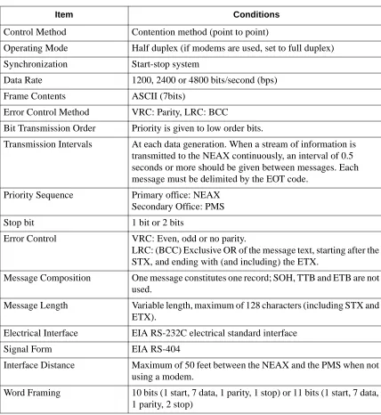
The characteristics of the signals transmitted across the communications link are as follows:
Table 2-1 Line Control Characteristics
Item Conditions
Control Method Contention method (point to point)
Operating Mode Half duplex (if modems are used, set to full duplex)
Synchronization Start-stop system
Data Rate 1200, 2400 or 4800 bits/second (bps)
Frame Contents ASCII (7bits)
Error Control Method VRC: Parity, LRC: BCC
Bit Transmission Order Priority is given to low order bits.
Transmission Intervals At each data generation. When a stream of information is transmitted to the NEAX continuously, an interval of 0.5 seconds or more should be given between messages. Each message must be delimited by the EOT code.
Priority Sequence Primary office: NEAX Secondary Office: PMS
Stop bit 1 bit or 2 bits
Error Control VRC: Even, odd or no parity.
LRC: (BCC) Exclusive OR of the message text, starting after the STX, and ending with (and including) the ETX.
Message Composition One message constitutes one record; SOH, TTB and ETB are not used.
Message Length Variable length, maximum of 128 characters (including STX and ETX).
Electrical Interface EIA RS-232C electrical standard interface
Signal Form EIA RS-404
Interface Distance Maximum of 50 feet between the NEAX and the PMS when not using a modem.
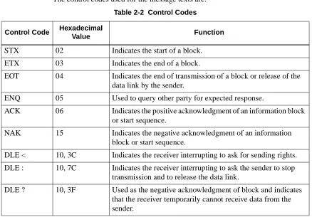
The control codes used for the message texts are:
Transmission
Protocol
Before a message can be sent, a start sequence (also called a selecting sequence) must be sent to urge the receiver to receive the data. Every transmission sequence will begin with the sender sending a start sequence.
The start sequence is a three byte sequence:
Figure 2-1 Start Sequence Table 2-2 Control Codes
Control Code Hexadecimal
Value Function
STX 02 Indicates the start of a block.
ETX 03 Indicates the end of a block.
EOT 04 Indicates the end of transmission of a block or release of the data link by the sender.
ENQ 05 Used to query other party for expected response.
ACK 06 Indicates the positive acknowledgment of an information block or start sequence.
NAK 15 Indicates the negative acknowledgment of an information block or start sequence.
DLE < 10, 3C Indicates the receiver interrupting to ask for sending rights.
DLE : 10, 7C Indicates the receiver interrupting to ask the sender to stop transmission and to release the data link.
DLE ? 10, 3F Used as the negative acknowledgment of block and indicates that the receiver temporarily cannot receive data from the sender.
05H
‘1’
‘!’
0 1 2
The messages (but not the control codes or start sequence) sent between the NEAX and the PMS must have header and trailing sections as defined in the following format:
Table 2-3 Base Message Format The message format breaks down as follows:
• STX -- Start of text block. (One byte - 02H.)
• SA -- System Address. (One byte - ‘1’ [31H].)
• UA -- I/O Unit Address. (One byte - ‘!’ [21H].)
• EI -- Entry Index. (One byte - ‘L’ [4CH].)
• FTC -- Feature Code. (See below.) A list is provided in Appendix C, “Feature Codes”.
• MSC -- Message Counter. This represents the length of the message. The count of characters starts at the FTC field and ends at the last character of the body of the message, not including the ETX. If the ETX character does not immediately follow the character specified by the message counter, an invalid message is assumed.
• FC -- Function Code. This specifies the individual operation and processing for the feature designated by the Feature Code (FTC). A list is provided in
Appendix D, “Function Codes”.
• ETX -- End of text block. (One byte - 03H.)
• BCC -- Block Check Code. This is computed by an exclusive OR of the message from the SA to the ETX (inclusive). Detection of an STX starts the computation (but the STX is not included). Detection of an ETX stops the computation (and the ETX is included). (One byte.)
Feature Codes range in value from 00 to FF (hex). These codes define the “Major Category Codes” for service features.
Codes from 80 to FF are used as “Violation Codes”. When a specific message received from the PMS cannot be processed for some reason, 80 (hex) is added to the received Feature Code so that it will be handled as a Violation Code. If the NEAX regards a text as a Violation Code, the system data of the NEAX may be assigned so that a text of this type is returned to the PMS. Therefore, when the PMS has received a Violation Code, provisions should be made for the PMS to print out this violation.
Block Check Code Range
02H ‘1’
‘!’
...
03H xx
0 1 2 3 4 6 8 9
STX SA UA EI FTC MSC FC Message ETX BCC
A Violation Code message will be sent to the PMS in the following cases:
• When the message counter does not match the number of characters received.
• When a station number not existing in the NEAX is specified in the message data from the PMS.
• Upon receipt of an invalid Wake Up time (e.g. 25:00).
Transmission
Sequence
The sequence of transmitting a message is slightly different for the PMS and NEAX. However, both sequences follow the same outline.
The party which desires to send must first bid for sender rights. This is done by sending the start sequence (see Figure 2-1). Once the start sequence has been sent and acknowledged, that party is now the “sender” and the other party is the “receiver”. (Unless both parties have simultaneously sent a start sequence. If this occurs, the PMS must relinquish sending rights to the NEAX.) The receiver must then respond with an answer control code (ACK, NAK, DLE <, DLE :, DLE ?) before the Sender Timer (see “Sender Timer” on page 10) expires.
If no answer control code is received, the sender will resend the start sequence and again wait for an answer control code.
When an answer control code is received, the sender must respond before the Receiver Timer (see “Receiver Timer” on page 10) expires. If the answer control code is an ACK, the sender must send the message. Again, the receiver must respond with an answer control code before the Sender Timer expires.
To finish the transmission sequence (regardless of its success), the sender must send an End Code (EOT) to release sending rights. Once that is done, both parties may begin the process over again by bidding for the sender rights.
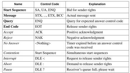
In the transmission sequence figures that follow, these message names are used:
Table 2-4 Message Names
Name Control Code Explanation
Start Sequence
SA, UA, ENQ
Bid for sender rights
Message
STX, ..., ETX, BCC
Actual message sent
Query
ENQ
Query for expected answer control code
End Code
EOT
Release sender rights
Accept
ACK
Positive acknowledgment
Reject
NAK
Negative acknowledgment
No Answer
<Nothing>
Timer expired before an answer control
code was received
Contention
Start Sequence
Simultaneous start sequences
Interrupt
DLE <
Request to release sender rights
Abort
DLE :
Demand to release sender rights
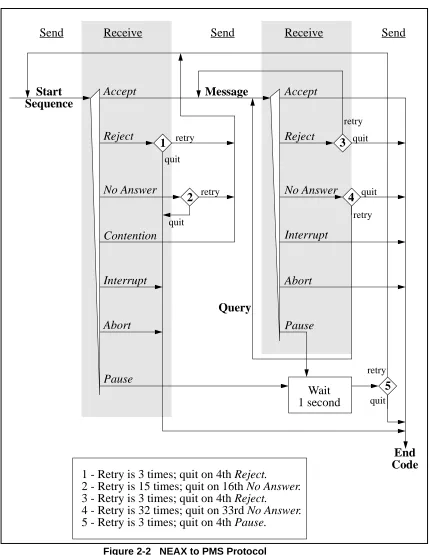
From the NEAX to the PMS
Figure 2-2 NEAX to PMS Protocol
Start
Sequence
Accept
Reject
No Answer
Contention
Interrupt
Abort
Pause
Message
Accept
Reject
No Answer
Interrupt
Abort
Pause
End
Code
Wait
1 second
Send
Receive
Send
Receive
Send
retry quit
retry
retry
retry
retry quit
quit
quit
quit
1
2
3
4
5
Query
1 - Retry is 3 times; quit on 4th Reject.
2 - Retry is 15 times; quit on 16th No Answer.
3 - Retry is 3 times; quit on 4th Reject.
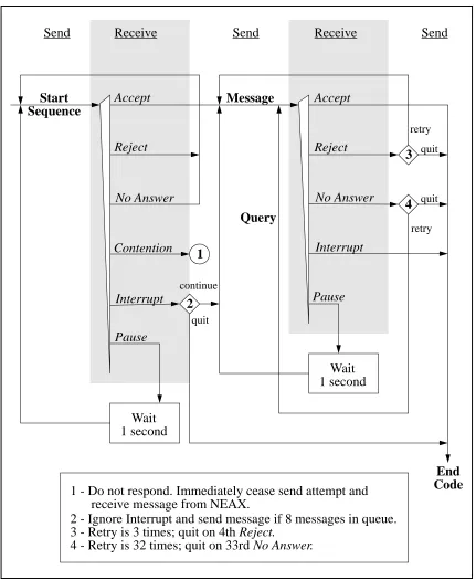
From the PMS to the NEAX
Figure 2-3 PMS to NEAX protocol
Start
Sequence
Accept
Reject
Contention
Interrupt
Pause
Message
Accept
Reject
No Answer
Interrupt
Pause
End
Code
Wait
1 second
Send
Receive
Send
Receive
Send
retry
quit
Query
Wait
1 second
No Answer
quitretry
continue
quit
1
2
3
4
1 - Do not respond. Immediately cease send attempt and
2 - Ignore Interrupt and send message if 8 messages in queue.
3 - Retry is 3 times; quit on 4th Reject.
Timers
The following timers are used to maintain data transmission:Sender Timer
Upon sending a start sequence, message text or query, this timer begins counting and stops counting upon receiving a valid answer control code. This timer is set to one (1) second. If a timeout occurs after the transmission of a start sequence, a start sequence will be resent up to 15 times. If a timeout occurs during the transmission of a message text or query, a query is sent up to 32 times.
Receiver Timer
Upon transmission of a positive acknowledgment for a start sequence or a message text, this timer begins counting and stops counting upon receiving a message text or an end code. This timer is set to 35 seconds. If a timeout occurs, the sender loses send rights.
Cabling
Considerations
When the PMS is connected to the NEAX through a modem, the cables should just be “straight through” cables. There should be no crossing.
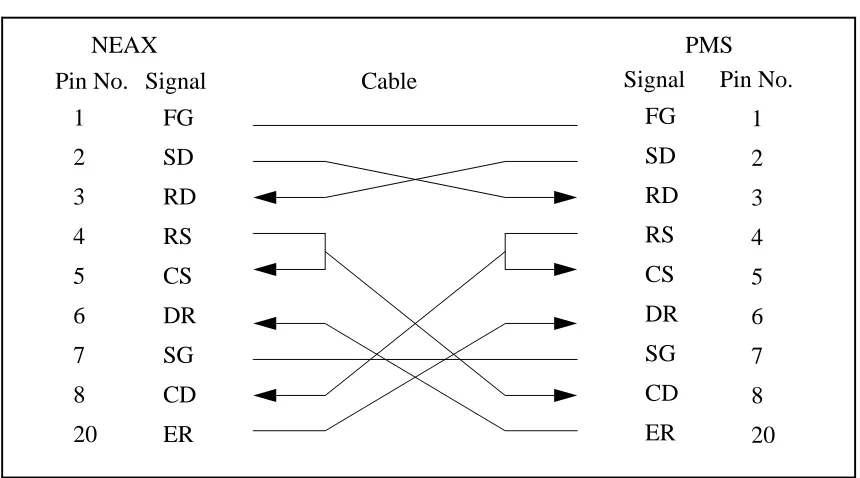
When the PMS is directly connected to the NEAX, use the following pin assignments:
Figure 2-4 Direct Connection Pin Assignments
Bisynchronous (BSC) Transmission
Line Control
Characteristics
The characteristics of the signals transmitted across the communications link are as follows:
1
FG
SD
RD
RS
CS
DR
SG
CD
ER
2
3
4
5
6
7
8
20
FG
SD
RD
RS
CS
DR
SG
CD
ER
1
2
3
4
5
6
7
8
20
Pin No. Signal
Cable
Signal
Pin No.
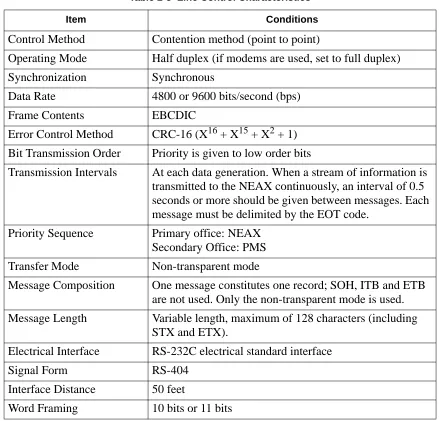
Table 2-5 Line Control Characteristics
Item Conditions
Control Method
Contention method (point to point)
Operating Mode
Half duplex (if modems are used, set to full duplex)
Synchronization
Synchronous
Data Rate
4800 or 9600 bits/second (bps)
Frame Contents
EBCDIC
Error Control Method
CRC-16 (X
16+ X
15+ X
2+ 1)
Bit Transmission Order
Priority is given to low order bits
Transmission Intervals
At each data generation. When a stream of information is
transmitted to the NEAX continuously, an interval of 0.5
seconds or more should be given between messages. Each
message must be delimited by the EOT code.
Priority Sequence
Primary office: NEAX
Secondary Office: PMS
Transfer Mode
Non-transparent mode
Message Composition
One message constitutes one record; SOH, ITB and ETB
are not used. Only the non-transparent mode is used.
Message Length
Variable length, maximum of 128 characters (including
STX and ETX).
Electrical Interface
RS-232C electrical standard interface
Signal Form
RS-404
Interface Distance
50 feet
The control codes used for the message texts are:
Table 2-6 Control Codes
Control Code Hexadecimal
Value Function
SYN
32
Synchronization code.
STX
02
Indicates the start of a block.
ETX
03
Indicates the end of a block.
ENQ
2D
Used as the start sequence code. It indicates a reception
request to the other side and a request to answer an
infor-mation block just sent.
EOT
04
Indicates the end of transmission of a block or release of
the data link by the sender.
ACK0
10, 70
Used alternately, these indicate the positive
acknowledg-ment of an information block or a start sequence.
ACK1
10, 61
NAK
3D
Indicates the negative acknowledgment of an
informa-tion block or a start sequence.
WACK
10, 6B
Used as the positive acknowledgment of an information
block or start sequence and indicates that the receiver
temporarily cannot receive data from the sender.
TTD
02, 2D
Indicates that the sender cannot transmit the next
infor-mation block after the receipt of the answer to the
previ-ous information block sent from the receiver.
RVI
10, 7C
Indicates the positive acknowledgment of an information
block and asks the sender for sending rights.
PAD-L
55
Indicates the absolute beginning of the entire
informa-tion block.
Transmission
Protocol
The messages sent between the NEAX and the PMS must have header and trailing sections as defined in the following format:
Figure 2-5 Base Message Format
The elements of the message is as follows:
• PAD-L -- The leading pad character. (One byte - 55H.)
• SYN -- Synchronization character. At least three of these should be transmitted. (One byte each - 32H.)
• STX -- Start of text block. (One byte - 02H.)
• Data -- The message data is describe below in Figure 2-6. • ETX -- End of text block. (One byte - 03H.)
• CRC-- Cyclic Redundancy Check. This is computed by an exclusive OR of the message from the SA to the ETX (inclusive). Detection of an STX starts the computation (but the STX is not included). Detection of an ETX stops the computation (and the ETX is included). (One byte.)
• PAD-T -- The trailing pad character. (One byte - FFH.) The message data is defined as follow:
Figure 2-6 Message Data Format
Cyclic Redundancy Check Area
02H
03H xx
STX Data ETX CRC PAD-T
FFH
32H
55H 32H
32H
PAD-LSYN SYN SYN
02H ‘1’
‘!’
...
03H
STX SA UA EI FTC MSC FC Message ETX
The message format breaks down as follows:
• STX -- Start of text block. (One byte - 02H.)
• SA -- System Address. (One byte - ‘1’ [31H].)
• UA -- I/O Unit Address. (One byte - ‘!’ [21H].)
• EI -- Entry Index. (One byte - ‘L’ [4CH].)
• FTC -- Feature Code. (See below.) A list is provided in Appendix C, “Feature Codes”.
• MSC -- Message Counter. This represents the length of the message. The count of characters starts at the FTC field and ends at the last character of the body of them message, not including the ETX. If the ETX character does not
immediately follow the character specified by the message counter, an invalid message is assumed.
• FC -- Function Code. This specifies the individual operation and processing for the feature designated by the Feature Code (FTC). A list is provided in
Appendix D, “Function Codes”.
• ETX -- End of text block. (One byte - 03H.)
Feature Codes range in value from 00 to FF (hex). These codes define the “Major Category Codes” for service features.
Codes from 80 to FF are used as “Violation Codes”. When a specific message received from the PMS cannot be processed for some reason, 80 (hex) is added to the received Feature Code so that it will be handled as a Violation Code. If the NEAX regards a text as a Violation Code, the system data of the NEAX may be assigned so that a text of this type is returned to the PMS. Therefore, when the PMS has received a Violation Code, provisions should be made for the PMS to print out this violation.
A Violation Code message will be sent to the PMS in the following cases:
• When the message counter does not match the number of characters received.
• When a station number not existing in the NEAX is specified in the message data from the PMS.
Transmission
Sequence
Table 2-7 Data Transmission Sequence (1 of 2)
Status ENQ STX ETX,
CRC
ACK0/
ACK1 NAK
Neutral (A)
a: ACK0 ->
(B)
b: NAK ->
(A)
c: ENQ ->
(D)
Waiting for
STX (B)
(ACK last
received) ->
(B)
-> (C)
Waiting for
ETX, CRC
(C)
f: NAK ->
(B)
g: EOT ->
(A)
h: ACK0/1
i: NAK
c: RVI
j: EOT
-> (A)
Waiting for
ACK after
start
sequence
(D)
f: ENQ ->
(D)
g: EOT ->
(A)
d: ENQ ->
(D)
e: EOT ->
(A)
d: ENQ ->
(D)
e: EOT ->
(A)
Message ->
(E)
j: EOT ->
(A)
f: ENQ ->
(D)
g: EOT ->
(A)
Waiting for
ACK after
message (E)
d: ENQ ->
(D)
e: EOT ->
(A)
d: ENQ ->
(D)
e: EOT ->
(A)
d: ENQ ->
(D)
e: EOT ->
(A)
k: Message
-> (E)
l: EOT ->
(A)
Notes:
• a: Preparation for reception complete.
• b: Reception impossible.
• c: Requests for preparation for reception (the PMS should not request this).
• d: Transmitted up to 21 times.
• e: Aborted at 22nd time.
• f: Transmitted up to 7 times.
• g: Aborted on the 8th time.
• h: Message is received normally and preparation for next reception is complete.
• i: Error found in message.
• j: Interruption.
• k: Information to be transmitted is present.
• l: Information to be transmitted is absent.
• m: Retransmission of message.
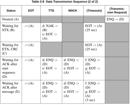
Table 2-8 Data Transmission Sequence (2 of 2)
Status EOT TTD WACK (Timeouts)
(Transmis-sion Request)
Neutral (A)
ENQ -> (D)
Waiting for
STX (B)
-> (A)
d: NAK ->
(B)
e: EOT ->
(A)
EOT -> (A)
(25 sec)
Waiting for
ETX, CRC
(C)
-> (A)
EOT -> (A)
(25 sec)
Waiting for
ACK after
start
sequence
(D)
-> (A)
d: ENQ ->
(D)
e: EOT ->
(A)
d: ENQ ->
(D)
e: EOT ->
(A)
f: ENQ ->
(D)
g: EOT ->
(A)
Waiting for
ACK after
message (E)
-> (A)
d: ENQ ->
(D)
e: EOT ->
(A)
d: ENQ ->
(D)
e: EOT ->
(A)
f: ENQ ->
(D)
g: EOT ->
(A)
Timers and
Counters
Retransmission Counts
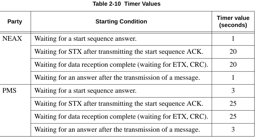
Timer Values
Table 2-9 Retransmission Counts
Meaning Count
The number of retransmissions of the start sequence when there is no
answer after transmitting the start sequence.
7
The number of retransmissions of the start sequence when NAK is
received after transmitting the start sequence.
7
The number of transmitting ENQs when WACK is received after the
transmission of an information block
15
The number of transmitting ENQs when there is no answer after the
transmission of an information block. (3 second intervals)
7
Table 2-10 Timer Values
Party Starting Condition Timer value
(seconds)
NEAX
Waiting for a start sequence answer.
1
Waiting for STX after transmitting the start sequence ACK.
20
Waiting for data reception complete (waiting for ETX, CRC).
20
Waiting for an answer after the transmission of a message.
1
PMS
Waiting for a start sequence answer.
3
Waiting for STX after transmitting the start sequence ACK.
25
Waiting for data reception complete (waiting for ETX, CRC).
25
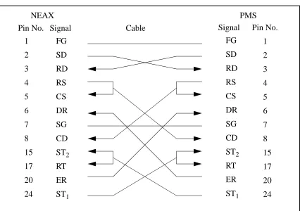
Cabling
Considerations
When the PMS is connected to the NEAX through a modem, the cables should just be “straight through” cables. There should be no crossing.
When the PMS is directly connected to the NEAX, use the following pin assignments:
Figure 2-7 Direct Connection Pin Assignments
1
FG
SD
RD
RS
CS
DR
SG
CD
ST
2RT
ER
ST
12
3
4
5
6
7
8
15
17
20
24
FG
SD
RD
RS
CS
DR
SG
CD
ST
2RT
ER
ST
11
2
3
4
5
6
7
8
15
17
20
24
Pin No. Signal
Cable
Signal
Pin No.
Chapter 3
Message Descriptions
There are several message groups:
• Data Link Maintenance Messages
• Maid Status
• Message Waiting Lamp Control
• Restriction Control
• Check In/Check Out (Model 60)
• Check In/Check Out (Model 90)
• Wake Up/Group Announcement
• Room Move/Swap/Copy (Model 60)
• Room Data Change
• Extension Report
• Room Recovery (Model 60)
• Room Recovery (Model 90)
• Direct Data Entry (Model 90)
• Extension Connection
Each message group will be described briefly in the following sections.
The NEAX equates rooms with extensions, one extension per room. The exception to this is the suite room feature. When this feature is activated in the NEAX, a primary extension represents a group of extensions in one or more rooms. For a suite room, the PMS should reference only the primary extension in its messages to the NEAX. All associated extensions will inherit the attributes of the primary extension and should effectively be ignored by the PMS.
Data Link Maintenance
These are the messages used by the PMS and NEAX to maintain communication.
The PMS must regularly send Nop Test messages with an interval of no more than 60 seconds, and no less than 500 milliseconds, between each message. The NEAX will immediately respond with either a Nop Test Normal Answer, under normal conditions, or a Nop Test Recover Answer, if a database recovery for the NEAX is needed.
• Nop Test Normal Answer -- Whenever a Nop Test message is sent by the PMS, the NEAX responds by sending this message, unless the NEAX has just finished an error recovery.
• Recovery Start Report -- After receiving the Nop Test Recover Answer message, the PMS must download NEAX database information (see “Room Recovery (Model 60)” on page 27 and “Room Recovery (Model 90)” on page 28). This message notifies the NEAX of the incoming download.
• Recovery End Report -- Reports to the NEAX that the PMS database download is complete.
• Data Link Release Request -- Used by either system to request a temporary release of the data link.
• Data Link Release Confirmation -- Reply to the above message to acknowledge data link release request.
• Extension Number Request -- Used by the PMS to request the current status of extension numbers.
• Nop Test -- Under the standard protocol the PMS must send this message at least every 60 seconds, but not less than 500 milliseconds, to demonstrate that communication has been maintained.
Data Link Failure
Either system may recognize a loss of communication by one or more of the following events:• Lack of system traffic for a 60 second interval: the Nop Test message from the PMS and the Nop Test Answer message (either Normal or Recover) from the NEAX insure that at least one message should be received less than every 60 seconds.
• Detection of hardware problems within the physical data. Note that the NEAX will put EIA pin number 6 (Data Set Ready) into the off state, indicating data set not ready, when the data link has been effectively turned off in the NEAX, either for maintenance or because of repeated, excessive errors.
• Excessive protocol errors (NAK’ed transmission, ENQ’s with no ACK/NAK response).
• Other conditions, such as unavailability of buffers or queuing capability, which result in an implied status change message which cannot be communicated to the other system.
• Release of the data link requested and confirmed.
Release for
Maintenance
Either system may request a temporary release of the data link for maintenance purposes by transmitting a Data Link Release Request message to the other system. The receiving system will perform any necessary processing and return the Data Link Release Confirmation message as soon as possible.
During the NEAX maintenance, the PMS may continue to send Nop Test
messages, provided that EIA pin 6 (Data Set Ready) from the NEAX is in the “on” condition. The NEAX will turn on the EIA pin 6 “on” and respond to Nop Test messages when maintenance is completed.
While the data link is release on request of the PMS, the NEAX will continue to attempt to read Nop Test messages from the PMS. The PMS may set EIA pin 20 (Data Terminal Ready) to the “off” condition to indicate that reading should not be attempted.
When EIA pin 20 is in the “on” state and a Nop Test message is received from the PMS, the NEAX will assume that PMS maintenance has ended and that
communication can be resumed.
NEAX Operations
During Loss of
Communication
The NEAX will continue to support the basic telecommunications functions if the data link or PMS become unavailable. Upon detection of a data link failure, the NEAX will automatically switch to the “Link Failed Mode” to perform the following tasks:
• Enable Check In and Check Out on the Attendant Console and Front Desk Terminal.
• Continue support of Message Waiting and/or Controlled Restriction if both features are active in the NEAX.
Recovery from
Loss of
Communication
In the event of a PMS failure, it is assumed that Check In and Check Out must be done manually and entered into the PMS system at a later time. The PMS should not resume transmission of the Nop Test message and attempt to reestablish communication until the database has been brought up to date. This prevents the transmission of incorrect data prematurely through the database recovery procedure.
In cases where the PMS has remained operational during a data link failure, the PMS will continue to attempt sending Nop Test messages. A Nop Test Answer message (either Normal or Recover) from the NEAX will indicate that
communication has been reestablished.
A Nop Test Normal Answer message indicates that the NEAX has had no status change during the data link failure period and has automatically switched back to the normal operating mode of an active data link.
A Nop Test Recover Answer message indicates that the NEAX has failed and that status memory has been initialized for each room with the following:
• Room Status is Occupied (Checked In),
• Controlled Restriction Level is set to the preassigned restriction,
• Message Waiting Lamps are off,
Maid Status
These messages are used by the NEAX to communicate the actions of the cleaning personnel. If the message is designated “Model 90” then that message is only used by the Model 90 version. The other messages are used by both versions.
• Cleaning Start (Guest)
• Cleaning End (Guest)
• Inspection End (Guest)
• Out of Order (Guest)
• Cleaning Start (Administration)
• Cleaning End (Administration)
• Inspection End (Administration)
• Guest Room 1 (Model 90)
• Guest Room 2 (Model 90)
• Guest Room 3 (Model 90)
• Guest Room 4 (Model 90)
• Guest Room 5 (Model 90)
• Guest Room 6 (Model 90)
• Guest Room 7 (Model 90)
Note: This message was not previously defined in NEAX2400 IMS Hotel System PMS Interface Specification.
• Negative Answer (Model 90)
• Positive Answer (Model 90)
• Administration 1 (Model 90)
• Administration 2 (Model 90)
• Administration 3 (Model 90)
• Administration 4 (Model 90)
Message Waiting Lamp Control
These messages are used to control the message waiting lamp on an extension. The message waiting lamp is used to notify a guest about the existence of text messages. If the message is designated “Model 90” then that message is only used by the Model 90 version. The other messages are used by both versions.
When the NEAX is configured to use the suite room feature, the primary extension represents all extensions in that suite. Therefore, a message set to the primary extension controls the message waiting lamps on all extensions in that suite.
• MWL On -- This message is sent by the PMS to turn on a message waiting lamp.
• MWL Off -- This message is sent by the PMS to turn off a message waiting lamp.
• MWL On -- This message is sent by the NEAX to notify the PMS that a message waiting lamp has been turned on.
• MWL Off -- This message is sent by the NEAX to notify the PMS that a message waiting lamp has been turned off.
• MWL Status -- This message is sent by the PMS. (Model 90)
• MWL On (FDT) -- This message is sent by the NEAX to notify the PMS that a message waiting lamp has been turned on by the front desk. (Model 90)
• MWL Off (FDT) -- This message is sent by the NEAX to notify the PMS that a message waiting lamp has been turned off by the front desk. (Model 90)
Restriction Control
There are two messages. They are identical except that one is originated by the PMS, the other by the NEAX. Each message simply transmits the restriction code. Both the Model 60 and the Model 90 version use these messages.
Check In/Check Out (Model 60)
These messages do not represent unique features as such, but are a convenient tool for activating a sequence of functions commonly performed when a guest checks in or out of a room. With one exception, all of these messages are used exclusively for Model 60. The sole exception is Check Out Outgoing Call Report, which is also used by Model 90.
When the NEAX is configured to use the suite room feature, the primary extension represents all extensions in that suite. Therefore, a message set to the primary extension controls the status of all extensions in that suite.
• Check In 1 -- Sets the Room Status to Stay and cancels Room Cut-Off. This message is sent by the PMS. This message should not be used. Use Check In 3 instead.
• Check Out Message Waiting Lamp Off Report -- This message is sent by the NEAX to report that the Message Category “Front” of that specific guest room is Off.
• Check Out Message Waiting Lamp On Report -- This message is sent by the NEAX to report that the Message Category “Front” of that specific guest room is On.
• Check In 2 -- Same as Check In 1, but also sets the Language and Room Stay. This message should not be used. Use Check In 3 instead.
• Check In 3 -- Same as Check In 2, but also sets the Guest Name and Group Number.
• Check Out Outgoing Call Report -- The NEAX sends this message if, after receiving a check out message from the PMS, it determines that the guest extension is engaged in an outgoing call.
• Check Out Message Waiting Report -- This message is generated by the NEAX to report the status of waiting messages.
Check In/Check Out (Model 90)
These messages do not represent unique features as such, but are a convenient tool for activating a sequence of functions commonly performed when a guest checks in or out of a room. All of these messages are used exclusively for Model 90. There is also the addition of the Check Out Outgoing Call Report message which is technically a Model 60 message, but is available for Model 90.
When the NEAX is configured to use the suite room feature, the primary extension represents all extensions in that suite. Therefore, a message set to the primary extension controls the status of all extensions in that suite.
• Check In -- This message is sent by the PMS to notify the NEAX of a check in. This cancels Room Cut-Off.
• Check Out -- This message is sent by the PMS to notify the NEAX of a check out.
• Check In Cancellation -- This message is sent by the PMS. It cancels a previously sent check in message. The room status is set to “Vacant.”
• Check Out Cancellation -- This message is sent by the PMS. It cancels a previously sent check out message. Under some circumstances the NEAX may fail to perform this function which means that the guest must be checked in again.
• Room Change -- This message is sent by the PMS to notify the NEAX of a guest room change.
• Provisional Check In -- This is a provisional check in message generated by the NEAX. The room status is set to “Stay” and Room Cut-Off is cancelled.
• Provisional Check Out -- This is a provisional check out message generated by the NEAX. If maid status is not performed, room status is set to “Vacant;” if maid status is performed, room status is set to “Out.”
Wake Up/Group Announcement
These messages allow for the management of wake up calls and group
announcements. Both the Model 60 and the Model 90 version use these messages.
• Wake Up Setting (NEAX) -- This message is sent by the NEAX to notify the PMS that a wake up call has been set.
• Wake Up Cancellation (NEAX) -- This message is sent by the NEAX to notify the PMS that a wake up call has been cancelled.
• Wake Up Execution Result -- This message is sent by the NEAX to report the results of the wake up call.
• Wake Up Setting(PMS) -- This message is sent by the PMS to set a wake up call.
• Wake Up Cancellation (PMS) -- This message is sent by the PMS to cancel a wake up call.
• Group Announcement Setting (NEAX) -- This message is sent by the NEAX to notify the PMS that a group announcement has been set.
• Group Announcement Cancellation (NEAX) -- This message is sent by the NEAX to notify the PMS that a group announcement has been cancelled.
• Group Announcement Execution Result -- This message is sent by the NEAX to report the results of a group announcement.
• Group Announcement Setting (PMS) -- This message is sent by the PMS to set a group announcement.
• Group Announcement Cancellation (PMS) -- This message is sent by the PMS to cancel a group announcement.
Room Move/Swap/Copy (Model 60)
These messages are used to transfer room information. All of these messages are used exclusively for Model 60. The messages are:
• Room Move -- This takes the data for one room and moves it to another room. This will leave the second extension’s maid status unchanged, cancels Room Cut-Off and sets all other data to that of the first extension. The first extension’s maid status is set to ‘1’, Room Cut-Off is set, Do Not Disturb and Message Waiting is reset, Wake Up is cancelled, Language is set to “Undefined” and Guest Name and Group Number are cleared.
• Room Swap -- This takes the data for one room and moves it to another room, while taking the other room’s data and moving it to the first room.
Room Data Change
These messages are used to change the room information while a guest is still checked in. Messages designated “Model 60” are only used by the Model 60 version; “Model 90” are only used by the Model 90 version. Messages with neither designation may be used by either version. The messages are as follows:
• Room Data Change 60 -- This is used to change room data after check in. This message is sent by the PMS. (Model 60)
• Group Formation -- This is used when adding a guest to a group or changing a guest’s group after check in. This message is sent by the PMS.
• Group Cancellation -- This is used to remove a guest from a group after check in. This message is sent by the PMS.
• Reservation Setting -- This is used to set reservation for a guest room. The reservation information is cleared by check in processing or when the room status becomes “Vacant” or “Out of Order”. (Model 60)
• Reservation Cancellation -- This cancels guest room reservation. (Model 60)
• Guest Name Change -- This is used to change the guest name after check in. This message is sent by the PMS. (Model 60)
• Room Data Change 90 -- This is used to change room data after check in. This message is sent by the PMS. (Model 90)
• Room Status Change -- This is used to change the room status and/or the cleaning status of the room after check in. This message is sent by the PMS. (Model 90)
• Room Key Status Change -- This is used to change the room key status after check in. This message is sent by the PMS. (Model 90)
Extension Report
Room Recovery (Model 60)
These messages are used by the PMS to update the database in the Model 60 version. These messages will usually only be sent if requested by the NEAX using the Nop Test Recover Answer message. However, the PMS may, if necessary, initiate a recovery with a direct request from the NEAX.
Before any recovery messages can be sent, the PMS must first send a Recovery Start Report message. After all information about rooms has been sent by recovery messages, a Recovery End Report message must be sent. Both of these messages are defined in the Data Link Maintenance section.
The recovery messages are grouped into three sets of four messages. Within each set of four messages, the format of the messages is identical, except for the Function Codes, which specify the message. Each set of messages contains more fields (and can therefore convey more information) than the preceding set.
Each set of four messages is composed of two pairs of messages. The PMS must use the same set of recovery messages during the recovery period. The first pair of messages is used when the PMS, in normal operation (i.e. not error recovery), needs to update the information on a given extension. The second pair of messages is used during recovery. This pair will only be used in response to the NEAX sending a Nop Test Recover Answer or Recovery Request message.
The first message (of either pair) is used by the PMS as an update/ request for information on an extension. If a field contains a valid entry, the NEAX database is updated; if the field is entirely filled with NULL (00H) characters, it is a request for the NEAX to send the value from the NEAX database. The second message is the response from the NEAX to the PMS.
• Room Image Set 1 -- Contains the following fields: Extension, Vacancy, MWL and Restriction Level.
• Room Image Set 2 -- In addition to the above fields, the following are added: Room Stay, Reserve, Language, Cleaning Status and Wake Up.
Room Recovery (Model 90)
These messages are used by the PMS to update the database in the Model 90 version after a failure recovery. These messages will usually only be sent if requested by the NEAX using the Nop Test Recover Answer message. However, the PMS may, if necessary, initiate a recovery with a direct request from the NEAX.
Before any recovery messages can be sent, the PMS must first send a Recovery Start Report message. After all information about rooms has been sent by recovery messages, a Recovery End Report message must be sent. Both of these messages are defined in the Data Link Maintenance section.
• Room Data Report -- Once Recovery has been requested by the NEAX, the PMS uses this message to report the data for each room.
• Guest Room Secretary Telephone -- This message is used to recover data for a secretary telephone.
• Connecting Room -- If any rooms are connecting, this message is used to establish the relationship.
• Message Status Report -- This reports the status of the Message Waiting Lamp.
• Wake Up -- Any wake up data is reported by this message.
Direct Data Entry (Model 90)
These messages are used to send numeric information from the NEAX to the PMS. An employee provides this information by entering an access code at a guest room telephone. Then the NEAX captures all numeric input following the access code and sends the digits to the PMS.
The NEAX expects to receive a response to this message within 30 seconds. If no response is sent, or a Negative Answer is received, a reorder tone will be heard. If a Positive Answer is received, the NEAX will recognize that the information has been entered successfully and the service set tone will be heard.
• Direct Data Entry -- This message is sent by the NEAX and contains the numeric information entered at the guest room telephone.
• Direct Data Entry Negative Answer -- This message is sent by the PMS to notify the NEAX that the numeric data sent from the specified guest room telephone has been rejected.
Extension Connection
These messages are used to associate extensions. This association will be either in the form of a Boss/Secretary or of a Master/Secondary. In either case, both of the rooms to be connected must be checked in. There may only be one Secretary for each Boss, but a Secretary may be assigned to multiple Bosses. A Master and Secondary may only be assigned on a one to one basis. The effect of the Boss/ Secretary association is that whenever the Boss extension is called, only the Secretary extension will ring. In the case of Master/Secondary, whenever the Master extension is called, both the Master extension and the Secondary extension will ring. All of these messages are used exclusively for Model 90.
• Guest Room Secretary Telephone (PMS) -- This message is sent by the PMS to set or cancel the guest room telephone.
• Guest Room Secretary Telephone (NEAX) -- This message is sent by the NEAX to notify the PMS that a guest room secretary telephone has been set or cancelled.
• Connecting Room Set -- This message is sent by the PMS to connect a main room with a sub room. This message should only be sent after both rooms have been checked in.
Chapter 4
Message Formats
All messages sent between the NEAX and the PMS must have header and trailing sections as defined in the following format:
Figure 4-1 Base Message Format
The message format breaks down as follows:
• STX -- Start of text block. (One byte - 02H.)
• SA -- System Address. (One byte - ‘1’ [31H].)
• UA -- I/O Unit Address. (One byte - ‘!’ [21H].)
• EI -- Entry Index. (One byte - ‘L’ [4CH].)
• FTC -- Feature Code. Used in conjunction with the Function Code to uniquely identify a message. A list of values are included in Appendix C, “Feature Codes”. (Two bytes.)
• MSC -- Message Count. This is the number of bytes from the FTC character up to the character before the ETX. (Two bytes.)
• FC -- Function Code. This entry is dependent on the FTC entry. A list of values are included in Appendix D, “Function Codes”. (One byte.)
• ETX -- End of text block. (One byte - 03H.)
• BCC -- Block Check Code. This is computed by an exclusive OR of the message from the SA to the ETX (inclusive). Detection of an STX starts the computation (but the STX is not included). Detection of an ETX stops the computation (and the ETX is included). (One byte.)
Note 1: Unless otherwise noted, if the data to be stored in a message field has fewer char-acters than the size of the field, all data must be left justified and the remaining characters must be filled with space (20H) characters.
Note 2: In the message diagrams, the STX, SA, UA, EI, FTC, MSC, FC and ETX fields will show the actual entries needed. The remaining fields will have the name of the field in the box and the length of the field below. For all fields, the beginning byte number is listed on the top of the field.
Block Check Code Range
02H ‘1’
‘!’
03H xx
** Options defined below
...
0 1 2 3 4 6 8 9
STX SA UA EI FTC MSC FC Message ETX BCC
**
**
**
Note 3: In the case of messages that are almost identical, the FC will be marked with “**”. Also, differing FTC values will be marked with “*”. The final message is then constructed by simply inserting the desired FC value (and, if necessary, the desired FTC value).
All messages in this section have been previously defined in NEAX2400 IMS Hotel
System PMS Interface Specification (except for one Maid Status message, which is
so noted). The versions supported are Model 60 and Model 90; Model 120 messages are not supported. Any message that is intended to work with only one version is so designated; any message that is intended to work with both has no special designation.
The Feature Codes used are as follows:
• 70 -- Data Link Maintenance
• 11, 12, 51, 52 -- Maid Status
• 13, 53 -- Message Waiting Lamp Control
• 15 -- Restriction Control
• 16 -- Check-In/Out (Model 60)
• 56 -- Check-In/Out (Model 90)
• 19 -- Wake Up/Group Announcement
• 20 -- Room Move/Swap/Copy (Model 60)
• 21, 61 -- Room Data Change
• 17 -- Extension Report
• 17 -- Room Recovery (Model 60)
• 57 -- Room Recovery (Model 90)
• 59 -- Direct Data Entry (Model 90)
• 62 -- Extension Connection
Data Link Maintenance
These messages are used by the NEAX and the PMS to maintain the data link between them. The messages are as follows:
• 70-0 -- Nop Test Normal Answer (Sent by NEAX)
• 70-2 -- Nop Test Recover Answer (Sent by NEAX)
• 70-3 -- Recovery Start Report (Sent by PMS)
• 70-4 -- Recovery End Report (Sent by PMS)
• 70-5 -- Data Link Release Request (Sent by PMS and NEAX)
• 70-6 -- Data Link Release Confirmation. (Sent by PMS and NEAX)
• 70-8 -- Extension Number Request (Sent by PMS)
The format of all Data Link Maintenance messages are exactly as follows:
Figure 4-2 Data Link Maintenance Message Format
The message format breaks down as follows:
• FC -- Function Codes that use this message format are: (FTC-FC)
• 70-0 -- Nop Test Normal Answer
• 70-2 -- Nop Test Recover Answer
• 70-3 -- Recovery Start Report
• 70-4 -- Recovery End Report
• 70-5 -- Data Link Release Request
• 70-6 -- Data Link Release Confirmation
• 70-8 -- Extension Number Request
• 70-F -- Nop Test
• Blank -- Field consists of two space (20H) characters.
Maid Status
This message group uses multiple Feature Codes. The code pairs are as follows (first number is the Feature Code, second number is the Function Code):
• 11-1 -- Cleaning Start (Guest)
• 11-2 -- Cleaning End (Guest)
• 11-3 -- Inspection End (Guest)
• 11-4 -- Out of Order (Guest)
• 12-1 -- Cleaning Start (Administration)
• 12-2 -- Cleaning End (Administration)
• 12-3 -- Inspection End (Administration)
• 51-1 -- Guest Room 1 (Model 90)
• 51-2 -- Guest Room 2 (Model 90)
• 51-3 -- Guest Room 3 (Model 90)
• 51-4 -- Guest Room 4 (Model 90)
• 51-5 -- Guest Room 5 (Model 90)
• 51-6 -- Guest Room 6 (Model 90)
** Multiple Function Codes use this message. See below.
0 1 2 3 4 6 8 9 11 12
STX SA UA EI FTC MSC FC 2
‘7’ ‘0’
‘0’
‘7’
**
Blank
02H ‘1’
‘!’
‘L’
03H xx
• 51-7 -- Guest Room 7 (Model 90)
Note: This message was not previously defined in NEAX2400 IMS Hotel System PMS Interface Specification.
• 51-8 -- Negative Answer (Model 90)
• 51-9 -- Positive Answer (Model 90)
• 52-1 -- Administration 1 (Model 90)
• 52-2 -- Administration 2 (Model 90)
• 52-3 -- Administration 3 (Model 90)
• 52-4 -- Administration 4 (Model 90)
All messages designated “Model 90” are used only by the Model 90 version. The other messages are used by either the Model 60 or the Model 90 version.
Cleaning
Figure 4-3 Cleaning (General)
Message fields are:
• FTC -- Feature Codes that use this message format are: 11 and 12.
• FC -- Function Codes that use this message format are: (FTC-FC)
• 11-1 -- Cleaning Start (Guest)
• 11-2 -- Cleaning End (Guest)
• 11-3 -- Inspection End (Guest)
• 11-4 -- Out of Order (Guest)
• 12-1 -- Cleaning Start (Administration)
• 12-2 -- Cleaning End (Administration)
• 12-3 -- Inspection End (Administration)
• Extension -- Extension number. If the extension number is less than six digits, left justify the number and fill the remaining bytes with space (20H) characters.
• Maid -- Identification number of the maid. If the maid identification number is less than six digits, left justify the number and fill the remaining bytes with space (20H) characters.
‘1’
*
‘1’
‘7’
** Extension
Maid
** Multiple Function Codes use this message. See below.
* Multiple Feature Codes use this message. See below.
0 1 2 3 4 6 8 9 15 21 22
STX SA UA EI FTC MSC FC 6 6
02H ‘1’
‘!’
‘L’
03H xx
Guest Room
Figure 4-4 Guest Room (General)
Message fields are:
• FC -- Function Codes that use this message format are: (FTC-FC)
• 51-1 -- Guest Room 1 (Model 90)
• 51-2 -- Guest Room 2 (Model 90)
• 51-3 -- Guest Room 3 (Model 90)
• 51-4 -- Guest Room 4 (Model 90)
• 51-5 -- Guest Room 5 (Model 90)
• 51-6 -- Guest Room 6 (Model 90)
• 51-7 -- Guest Room 7 (Model 90)
Note: This message was not previously defined in NEAX2400 IMS Hotel System PMS Interface Specification.
• Extension -- Extension number. If the extension number is less than six digits, left justify the number and fill the remaining bytes with space (20H) characters.
• Maid -- Identification number of the maid. If the maid identification number is less than six digits, left justify the number and fill the remaining bytes with space (20H) characters.
• LEN -- Line Equipment Number.
** Multiple Function Codes use this message. See below.
LEN
‘5’
‘1’ ‘2’
‘3’
** Extension
Maid
0 1 2 3 4 6 8 9 15
STX SA UA EI FTC MSC FC 6 6
02H ‘1’
‘!’
‘L’
03H xx
ETX BCC
21 27 28
Room Answer
Figure 4-5 Room Answer (General)
Message fields are:
• FC -- Function Codes that use this message format are: (FTC-FN)
• 51-8 -- Negative Answer (Model 90)
• 51-9 -- Positive Answer (Model 90)
• Extension -- Extension number. If the extension number is less than six digits, left justify the number and fill the remaining bytes with space (20H) characters.
• LEN -- Line Equipment Number.
• Request -- Room Status Change Request. The possible values are:
• 0 -- Room Status is not to be changed.
• 1 -- Room Status is to be changed.
• Room Status -- Room status. This flag is used in conjunction with the cleaning status flag to determine the status of the room.
• Cleaning Status -- Cleaning status. The possible combinations with room status are listed below:
LEN
** Multiple Function Codes use this message. See below.
Request
Room
Status
Cleaning
Status
‘5’
‘1’ ‘2’
‘0’
** Extension
0 1 2 3 4 6 8 9 15 21
STX SA UA EI FTC MSC FC 6 6 1
02H ‘1’
‘!’
‘L’
03H xx
ETX BCC
22 23 24 25
1 1
2
2
0
0
0
0
0
1
0
1
2
4
Stay, Departure Day
Stay, Departure Day, Cleaning in progress
Out (Checked Out)
Out, Cleaning in progress
Out, Cleaning ended
Out of Order (Cannot sell)
Room
0
1
1
Clean
3
0
1
Status of the Room
Vacant (Ready to sell)
Stay (Occupied)
Stay, Cleaning in progress
1
1
2
3
Administration
Figure 4-6 Administration (General)
Message fields are:
• FC -- Function Codes that use this message format are: (FTC-FC)
• 52-1 -- Administration 1 (Model 90)
• 52-2 -- Administration 2 (Model 90)
• 52-3 -- Administration 3 (Model 90)
• 52-4 -- Administration 4 (Model 90)
• Extension -- Extension number. If the extension number is less than six digits, left justify the number and fill the remaining bytes with space (20H) characters.
• Maid -- Identification number of the maid. If the maid identification number is less than six digits, left justify the number and fill the remaining bytes with space (20H) characters.
• LEN -- Line Equipment Number.
** Multiple Function Codes use this message. See below.
‘5’
‘2’ ‘2’
‘3’
** Extension
Maid
0 1 2 3 4 6 8 9 15
STX SA UA EI FTC MSC FC 6 6
02H ‘1’
‘!’
‘L’
03H xx
ETX BCC
21 27 28
Message Waiting Lamp Control
These messages are used to control the message waiting lamps on all of the phones. Messages sent by the PMS are commands to turn a message waiting lamp on or off. Messages sent by the NEAX are notification that a message waiting lamp has been turned on or off. This message group uses multiple Feature Codes. The code pairs are as follows (first number is the Feature Code, second number is the Function Code):
• 13-1 -- MW Lamp On (Sent by PMS)
• 13-2 -- MW Lamp Off (Sent by PMS)
• 13-3 -- MW Lamp On (Sent by NEAX)
• 13-4 -- MW Lamp Off (Sent by NEAX)
• 53-1 -- MW Lamp Status (Model 90)
• 53-2 -- MW Lamp On - FDT (Sent by NEAX) (Model 90)
• 53-3 -- MW Lamp Off - FDT (Sent by NEAX) (Model 90)
All messages designated “Model 90” are used only by the Model 90 version. The other messages are used by either the Model 60 or the Model 90 version. All messages apply to text message status only.
MWL Control
Figure 4-7 MWL Control (General)
Message fields are:
• FC -- Function Codes that use this message format are: (FTC-FC)
• 13-1 -- MWL On (Sent by PMS)
• 13-2 -- MWL Off (Sent by PMS)
• 13-3 -- MWL On (Sent by NEAX)
• 13-4 -- MWL Off (Sent by NEAX)
• 53-2 -- MWL On - FDT (Sent by NEAX) (Model 90)
• 53-3 -- MWL Off - FDT (Sent by NEAX) (Model 90)
• Extension -- Extension number. If the extension number is less than six digits, left justify the number and fill the remaining bytes with space (20H) characters.
*
‘3’ ‘1’
‘1’
** Extension
** Multiple Function Codes use this message. See below.
* Multiple Feature Codes use this message. See below.
0 1 2 3 4 6 8 9 15 16
STX SA UA EI FTC MSC FC 6