A Comparative Analysis of Different
Multilevel Inverters
Madhusudhana J1, P S Puttaswamy2, Harshit Agrawal3
Assistant Professor, Dept. of Electrical Engineering, UVCE, Bengaluru, India1 Professor, Dept. of Electrical &Electronics Engineering,PESCE, Mandya, India2
PG Student (P E), Dept. of Electrical Engineering, UVCE, Bengaluru, India 3
ABSTRACT: In recent days, power demand is continuously increasing. Therefore, the use of nonconventional energy sources is rapidly increasing. Among the various non-conventional sources solar energy is more promising one. The Solar energy is converted into electricity using Photovoltaic modules whose output is DC in nature. This DC is required to convert into Ac using multilevel inverters. In multilevel inverters as the number of levels in the output voltage increases, the accuracy of the system increases and the output voltage approaches nearer to the sinusoidal. As the levels in multilevel inverter increases, the complexity of the system increases due to their control strategy requirement. So at every stage user has to make a trade off with the quality of the output and complexity of the circuit. This paper deals with the 5, 7, 9, 11 levels of H bridge cascaded inverters and the simulation studies using MATLAB/Simulink software, withequal angle switching and equal area switching methods for different levels of inverters. A comparative study between different parameters of the multilevel inverters is performed for the selection of required multilevel inverter. The results obtained are also presented.
KEYWORDS: Multilevel inverter, MATLAB/Simulink, equal angle method, equal area method, THD
.
I.INTRODUCTION
As the cost of fossil fuels continue to rise, other sources of energies are becoming important. Renewable energy sources (solar, wind, fuel cell etc) are considered as alternative energy sources to conventional fossil fuel energy sources due to environmental pollution and global warming problems. Solar energy is one of the most promising renewable sources that can be used to produce electric energy through photovoltaic (PV) process. A significant advantage of PV system is the use of abundant and free energy from the sun. However, these systems still face major obstacles that limit their widespread use due to their high cost and low efficiency when compared with other renewable technologies. Moreover, the intermittent nature of the output power of PV systems reduces their reliability in providing continuous power to customers. In addition, the fluctuations in the output power due to variations in irradiance and presence of harmonics might lead to undesirable performance of the electric network. Grid-connected PV-Systems consist of three main blocks: DC bus (PV panels), power converter and electrical network. The power converter acts as an interface between the DC voltage, and AC grid, injecting power into electrical network. The DC/AC conversion is performed in this power converter introduces harmonics, some power losses such as switching losses, conduction losses and losses in reactive elements. An optimal design is needed to reduce these losses so that a reliable quality output and higher efficiency is obtained.
ISSN (Print) : 2320 – 3765 ISSN (Online): 2278 – 8875
I
nternational
J
ournal of
A
dvanced
R
esearch in
E
lectrical,
E
lectronics and
I
nstrumentation
E
ngineering
(An ISO 3297: 2007 Certified Organization)
Vol. 5, Issue 7, July 2016
II.CASCADE H-BRIDGE MULTILEVEL INVERTER
The basic topology of H-bridge multilevel inverter with symmetrical switches is shown in figure 2.1 (a)(b). This type of topology consists of several H-bridges connected in cascade, with every unit having its own dc source. With different combination of sources corresponding to the switching pattern, different levels of output voltage can be obtained. The required number of levels in the output is given by the equation[3],
= 2 + 1
Where M = Number of levels, S = Number of H-bridges, The output of the multilevel inverter should be quarter symmetric to generate a sine wave. Due to quarter wave symmetry even harmonics are absent in the output of the multilevel inverter. There are various switching scheme available to generate the output voltage waveform, in which fundamental switching scheme is the simplest one.Fig 2.1. (a)Single phase H-bridge multilevel inverter circuit diagram and (b)output waveform
Generated output voltage waveform by fundamental switching scheme is shown in fig 1(b). The Fourier series expansion of the output voltage waveform can be given as follows [3]
( ) =∑ , .... [ . cos( )+ . cos( ) + . cos( )+. . + cos( )] sin( ) … (1)
Where and are the voltage value and switching angle for the Sth voltage source.
For any waveform which not sinusoidal in nature, then its Fourier expansion contains components respective to the multiple of fundamental frequency. From equation (1), we can observe that the obtained output waveform is not a sinusoidal and it contains harmonics which reduce output quality. Different topologies and control strategies have been proposed for different levels of output to improve the performance of multilevel inverters for practical application.[5][6] There are various algorithms and switching schemes available to remove most severe harmonics [2]. In this paper we are depicting the parameters of different level inverters. The results of this paper can be used for further analysis.
III.ANALYSIS OF DIFFERENT LEVEL INVERTERS
3.1- Five Levels H-BridgeMultilevel Inverter
Fig.3.1(a) Five Level Circuit Diagram and (b) Waveform
Fig 3.1(c).MATLAB/Simulink model of 5 level MLI and Table 3.1 Switching Table for 5 Level Inverter
3.2 Seven Level H-Bridge Multilevel Inverter
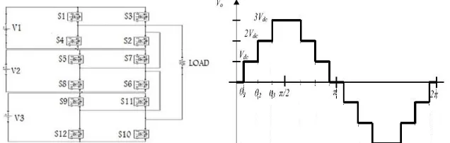
The concept of this inverter is based on connecting 3 H-bridge inverters with separate DC sources in cascade to get a sinusoidal voltage output. The output voltage is the sum of the voltage that is generated by each cell. Figure 3.2(a) shows a seven level cascaded bridge multilevel inverter. The converter consists of three series connected H-bridge cells which are fed by independent symmetrical voltage sources of 104volts. The outputs of the H-H-bridge cells are connected in series such that the synthesized voltage waveform is the sum of all of the individual cell outputs. The output voltage is given by V=V1 +V2 +V3 Where the output voltage of the first cell is labelled V1 and the output voltage of the second cell is denoted by V2 and the output voltage of the Third cell is denoted by V3. There are seven level of output voltage i.e. 3V, 2V, V, 0, -V, -2V,-3V. In this analysis to get 315 volts peak at the load we have used 3 H- Bridges of symmetrical DC input voltages of 104 volts.
Fig 3.2 Seven-level H-bridge multilevel inverter (a) circuit diagram and (b) waveform
S1 S2 S3 S4 S5 S6 S7 S8
2v 1 1 0 0 1 1 0 0
V 1 1 0 0 0 1 0 0
0 0 0 0 1 0 0 0 1
-v 0 0 1 1 0 1 0 0
-2v
ISSN (Print) : 2320 – 3765 ISSN (Online): 2278 – 8875
I
nternational
J
ournal of
A
dvanced
R
esearch in
E
lectrical,
E
lectronics and
I
nstrumentation
E
ngineering
(An ISO 3297: 2007 Certified Organization)
Vol. 5, Issue 7, July 2016
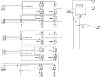
Fig 3.2(c).MATLAB/Simulink model of 7level MLI Table 3.2 Switching Table for 7 Level Inverter
3.3 Nine Level H-Bridge Multilevel Inverter
The concept of this inverter is based on connecting four H-bridge inverters with separate DC sources in cascade to get a sinusoidal voltage output. The general function of this multilevel inverter is to synthesis a desired voltage from several Separate DC Sources (SDCSs), which may be obtained from photovoltaic cells. The output voltage is the sum of voltage that is generated by each cell. Figure 3.3 shows a nine level cascaded H-bridge multilevel inverter. The converter consists of four series connected H-bridge cells which are fed by independent voltage sources of 78 volts. The output of the H-bridge cells is connected in series such that the synthesized voltage waveform is the sum of all of the individual cell outputs. The output voltage is given by V=V1 +V2 +V3+V4 Where the output voltage of the first cell is labelled V1 and the output voltage of the second cell is denoted by V2 , the output voltage of the Third cell is denoted by V3 and the output voltage of the fourth cell is denoted by V4. There are nine level of output voltage i.e. 4V, 3V, 2V, V, 0, -V, -2V,-3V,-4V. In this analysis to get 315 volts peak at the load we have used four H-bridgesofsymmetricalDC input voltages of 78 volts.
Fig 3.3.Nine level H-bridge multilevel inverter (a) circuit diagram and (b) waveform
S 1 S 2 S 3 S 4 S 5 S 6 S 7 S 8 S 9
S10 S1 1
S12
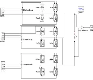
Fig 3.3 (c). Simulink model for nine level h-bridge inverter
Table 3.3: Switching Table for 9 Level Multilevel Inverter
3.4 Eleven Level H-Bridge Multilevel Inverter
The concept of this inverter is based on connecting five H-bridge inverters with separate DC sources in cascade to get more close to sinusoidal voltage output. The general function of this multilevel inverter is to synthesis a desired voltage from several Separate DC Sources (SDCSs), which may be obtained from batteries, fuel cells, or ultra-capacitors. The output voltage is the sum of the voltage that is generated by each cell. Figure shows a nine level cascaded H-bridge multilevel inverter. The converter consists of five series connected H-bridge cells which are fed by independent voltage sources of 63 volts. The outputs of the H-bridge cells are connected in series such that the synthesized voltage waveform is the sum of all of the individual cell outputs. The output voltage is given by V=+ + ++ ++ Where the output voltage of the first cell is labelled and the output voltage of the second cell is denoted by , the output voltage of the Third cell is denoted by , the output voltage of the fourth cell is denoted by V4 and the output voltage of the fifth cell is denoted by + . There are seven level of output voltage ie 5V,4V,3V, 2V, V, 0, -V, -2V,-3V,-4V,-5V. In this analysis to get 315 volts peak at the load we have used 5 H- bridges of symmetrical DC input voltages of 63 volts.
S1 S2 S3 S4 S5 S6 S7 S8 S9 S10 S11 S12 S13 S14 S15 S16
4v 1 1 0 0 1 1 0 0 1 1 0 0 1 1 0 0
3V 1 1 0 0 1 1 0 0 1 1 0 0 0 1 0 0
2V 1 1 0 0 1 1 0 0 0 1 0 0 0 1 0 0
V 1 1 0 0 0 1 0 0 0 1 0 0 0 1 0 0
0 0 0 0 1 0 0 0 1 0 0 0 1 0 0 0 1
-v 0 0 1 1 0 0 0 1 0 0 0 1 0 0 0 1
-2v 0 0 1 1 0 0 1 1 0 0 0 1 0 0 0 1
-3v 0 0 1 1 0 0 1 1 0 0 1 1 0 0 0 1
ISSN (Print) : 2320 – 3765 ISSN (Online): 2278 – 8875
I
nternational
J
ournal of
A
dvanced
R
esearch in
E
lectrical,
E
lectronics and
I
nstrumentation
E
ngineering
(An ISO 3297: 2007 Certified Organization)
Vol. 5, Issue 7, July 2016
Fig 3.4.Eleven level H-bridge multilevel inverter (a) circuit diagram and (b) waveform
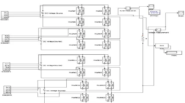
Fig 3.4 ( c). Simulink model for eleven level h-bridge inverter
Table 3.4. Switching Table for Eleven Level Inverter
IV.SIMULATION RESULTS USING MATLAB/SIMULINK
4.1 Five Level multilevel inverter
(a)Equal angle method (b) Equal area method Fig 4.1 Output voltage waveform for Five level MLI
The 5 level inverter has been simulated using MATLAB/Simulink by considering a resistive load of 25 ohms. It makes use of two separate DC sources of equal magnitude for the two H-bridges of the inverter circuit. The magnitude of the DC sources considered for analysis are Vdc1=Vdc2=156V each to get an AC output of 220V RMS. The simulation results obtained are tabulated in table 4.5.
(c ) Equal angle method (d) Equal area method Fig4.1 FFT analysis of Five level MLI output
Figure 4.1 shows the simulated output voltage waveforms and FFT analysis chart for the five level inverter considered. The graph also shows the percentage of different harmonics present in the output signal. The FFT graph shows that7th harmonic is dominant compared to 3rd and 5th harmonics.
4.2 Seven Level Multilevel Inverter
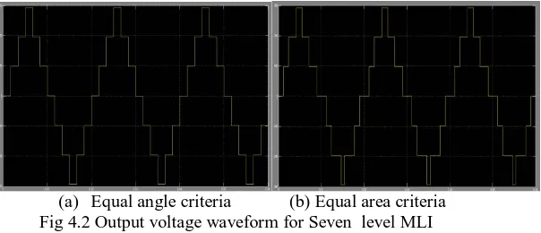
(a) Equal angle criteria (b) Equal area criteria Fig 4.2 Output voltage waveform for Seven level MLI
ISSN (Print) : 2320 – 3765 ISSN (Online): 2278 – 8875
I
nternational
J
ournal of
A
dvanced
R
esearch in
E
lectrical,
E
lectronics and
I
nstrumentation
E
ngineering
(An ISO 3297: 2007 Certified Organization)
Vol. 5, Issue 7, July 2016
sources considered for analysis are Vdc1=Vdc2=Vdc3=104V each to get an AC output of 220V RMS. The simulation results obtained are tabulated in table 4.5.
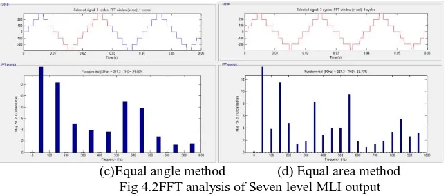
(c)Equal angle method (d) Equal area method Fig 4.2FFT analysis of Seven level MLI output
Figure 4.2 shows the simulated output voltage waveforms and FFT analysis chart for the seven level inverter considered. The graph also shows the percentage of different harmonics present in the output signal. The FFT graph shows that 3rd harmonic is dominant compared to other harmonics.
4.3- Nine Level Multilevel Inverter
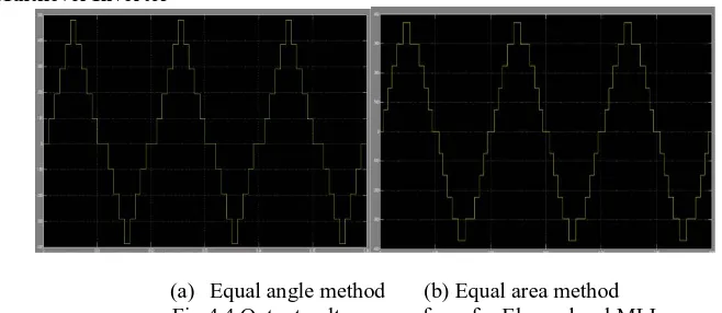
(a) Equal angle method (b) Equal area method Fig 4.3Output voltage waveform for Nine level MLI
The 9 level inverter has been simulated using MATLAB/Simulink by considering a resistive load of 25 ohms. It makes use of four separate DC sources of equal magnitude for the four H-bridges of the inverter circuit. The magnitude of the DC sources considered for analysis are Vdc1=Vdc2=Vdc3=Vdc4=78V each to get an AC output of 220V RMS. The simulation results obtained are tabulated in table 4.5.
Figure 4.3 shows the simulated output voltage waveforms and FFT analysis chart for the nine level inverter considered. The graph also shows the percentage of different harmonics present in the output signal. The FFT graph shows that 3rd harmonic is dominant in case of equal angle method and 11th harmonic is dominant in case of equal area method.
4.4 Eleven Level Multilevel Inverter
(a) Equal angle method (b) Equal area method Fig 4.4 Output voltage waveform for Eleven level MLI
The 11 level inverter has been simulated using MATLAB/Simulink by considering a resistive load of 25 ohms. It makes use of five separate DC sources of equal magnitude for the five H-bridges of the inverter circuit. The magnitude of the DC sources considered for analysis are Vdc1=Vdc2=Vdc3=Vdc4=Vdc5=63V each to get an AC output of 220V RMS. The simulation results obtained are tabulated in table 4.5.
( c) Equal angle method (d) Equal area method Fig 4.4FFT analysis of 11 level MLI output
Figure 4.4 shows the simulated output voltage waveforms and FFT analysis chart for the eleven level inverter considered. The graph also shows the percentage of different harmonics present in the output signal. The FFT graph shows that 3rd harmonic is dominant in both the methods as compared to other harmonics.
Table 4.1 Comparative Analysis Of Results Of Inverters
Levels Input voltage
(each dc source) Equal Angle method Equal Area method
THD
fundamental (50 hz)
Output
Voltage(rms) THD
fundamental (50 hz)
Output Voltage(rms)
5 Level 156×2 29 255 182v 36.87 192.9v 145.4v
7 Level 104×3 21.71 254 184.6v 23.37 236.4v 171.61v
9 Level 78×4 17.97 247.5 177.7v 14.83 251.9 180v
ISSN (Print) : 2320 – 3765 ISSN (Online): 2278 – 8875
I
nternational
J
ournal of
A
dvanced
R
esearch in
E
lectrical,
E
lectronics and
I
nstrumentation
E
ngineering
(An ISO 3297: 2007 Certified Organization)
Vol. 5, Issue 7, July 2016
V. CONCLUSION
In multilevel inverter applications the quality of output voltage is the main constraint. Since the output of multilevel inverter is not perfect AC in nature, one has to take care about the percentage THD at the output. From the simulation studies the percentage THD with both the methods Equal Angle method and Equal Area method is shown. From the table 4.5, it is concluded that the output derived approaching more sinusoidal as the levels in the output voltage is increased. However, the Output voltage and output power remains almost constant even the levels are changed. There are various aspects involved that has to be taken care while selecting or analysing any kind of multilevel inverter, one of which is the quality of sine wave the multilevel inverter is providing at the output. In this paper different multilevel inverters are simulated using MATLAB/Simulink software successfully and the obtained results with waveforms are tabulated in a comparative manner for a resistive load of 25Ω to validate the implementation.
REFERENCES
1. J-S. Lai and F.Z. Peng, “Multilevel converters – a new breed of power converters,” IEEE Trans. Ind. Appl., vol. 32, no. 3, pp. 509-517, May/June 1996.
2. Jih-Sheng Lai and Fang ZhengPeng and José Rodríguez “Multilevel Inverters: A Survey of Topologies, Controls, and Applications” IEEE Trans. On industrial electronics. VOL. 49, NO. 4, pp. 724-738 AUGUST 2002.
3. Zahra Bayat and EbrahimBabaei” Low Order Harmonics Elimination in Multilevel Inverters Using Fuzzy Logic Controller Considering the Variations of DC Voltage Sources”IEEE Conference on Electrical Machines and Systems (ICEMS), pp, 1-6 20-23 Aug. 2011
4. G. Carrara, S. Gardella, M. Marchesoni, R. Salutari, and G. Sciutto, “A new multilevel PWM method a theoretical analysis,” IEEE Trans. Power Electron., vol. 7, no. 4, pp. 497-505, Nov./Dec. 1989.
5. H.S. Patel and R.G. Hotf, “Generalized techniques of harmonic elimination and voltage control in thyristor inverters: part I– Harmonic elimination,” IEEE Trans. Ind. Appl., vol. 3, no. 3, May/June 1973.
6. P.N. Enjeti, P.D. Ziogas, and J.S. Lindsay, “Programmed PWM techniques to eliminate harmonics a critical evaluation,” IEEE Trans. Ind. Appl., vol. 26; no. 2; pp. 302-16, 1990.
7. J.S. Chassan, L.M. Tolbert, K.J. Mckenze, and Z. Du, “Control of a multilevel converter using resultant theory,” IEEE Trans. Control Syst. Theory, vol. 11, pp. 345-54, 2003.
8. F.-S. Shyu and Y.-S. Lai, “Virtual stage pulse-width modulation technique for multilevel inverter/converter,” IEEE Trans. Power Electron., vol. 17, pp. 332–341, May 2002.
9. Sinha and T. A. Lipo, “A four level rectifier-inverter system for drive applications,” in Proc. Conf. Rec. 1996 IEEE IAS Annu. Meet., Oct. 1996, pp. 980–987.
10. J. K. Steinke, “Control strategy for a three phase AC traction drive with three level GTO PWM inverter,” in IEEE Power Electronic Specialists Conf., 1988, pp. 431–438.
11. M. H. Ohsato, G. Kimura, and M. Shioya, “Five-stepped PWM inverter used in photo-voltaic systems,” IEEE Transactions on Industrial Electronics, Vol. 38, October, 1991, pp. 393-397.
12. J. Rodriguez, J.-S. Lai, and F. Z. Peng, “Multi-level inverter: a survey of topologies, controls, and applications,”IEEE Trans.Ind.Electron , vol. 49, no. 4, pp. 724–738, Aug. 2002