© 2018 IJSRCSEIT | Volume 4 | Issue 5 | ISSN : 2456-3307
Conversion of Single Phase AC to Three Phase AC Supply
Gaurav Sharma
*1, Naimish Kumar Bareek
2*1Electrical and Electronics Engineering, New Horizon College of Engineering, Bengaluru, Karnataka, India
2Electrical and Electronics Engineering, New Horizon College of Engineering, Bengaluru, Karnataka, India
ABSTRACT
This paper presents a simple converter topology for driving a load with a single-phase AC supply. Using only six active switch IGBT‟s(FGH40N60SFD). The converter supplies balanced output voltages at rated frequency, the proposed control approaches are supported by test results. The convertor takes single phase supply and converts it into three phase supply with the help of thyristors. The single phase supply is first converted into dc supply by using rectifier again dc supply of rectifier is given to inverter where IGBT‟s are used and converts the dc supply again into three phase ac supply. In the proposed scheme, Arduino Uno/Mega ADK microcontroller interfaced with Scilab(5.5.2) is used to produce PWM signals. The PWM signals generated is given to IC FAN7392(driver IC) which drives the thyristors. Three phase machines can be run on this by converting single phase to three phase AC supply wherever three phase AC supply is absent. Three phase induction motor can be used as load for testing of the hardware. For example, electric vehicles. The experimental result showed that PWM pulses produced remained approximately constant and the hardware have satisfactorily converted the single phase power to three phase power supply.
Keywords : Single Phase AC to Three Phase AC supply, IGBTs, drive system.
I.
INTRODUCTION
In the past, single-phase to three-phase conversion systems were made possible by the connection of passive elements capacitors and reactors with autotransformer converters. Such kind of system presents well know disadvantages and limitations. So to overcome from this disadvantages the newly adopted thyristors and power electronics devices were used mainly thyristors like
SCRs, MOSFETs, IGBTs etc.
Both have the advantages of simple structure and reasonably low cost. The project is about „single phase to three phase conversion system using IGBTs. Since the beginning of the solid state power electronics, the semiconductor devices were the major technology used to drive the power processors. Looking at the semiconductor devices used in the former controlled rectifiers and comparing them with the new technologies it makes possible to figure out the astonishing Development. Beyond the improvement related to power switches, it was also identified a great activity in terms of the circuit topology innovations in the field of three-phase to three-three-phase, single three-phase to single three-phase and three-phase to single phase conversion systems. The single-phase induction motor drives by the three-phase
induction motor drives in some low-power industrial applications. When the three phase induction motor is
driven by a single phase induction motor byrotary phase
converters and autotransformer capacitor phase
converters, this causes more loss as compared to the new
this method. Motor drives constitute a predominant load
for the agricultural sector. As most rural communities in the India are supplied with single-phase ac power, these drives have to be realized with single-phase motors, or with three phase motors (Induction Motors) driven by phase converters. Autotransformer capacitor phase converters, however, cannot easily obtain balanced output voltage with reasonable cost, and rotary converters are heavy and have significant no-load losses, also both topologies have high inrush current during motor start up.
every stage of manufacturing and processing. It is not surprising to find that among all type of electric motors, Induction motor is so popular, when one considers its simplicity, reliability, and low cost.
Therefore, it is desirable to replace the single-phase induction motor drives by the three-phase induction motor drives in some low-power industrial applications in some rural areas where only a single-phase utility is available, we should convert a single-phase to a three-phase supply. This paper proposes an alternative solution for phase conversion with very low overall cost, moderate motor performance during start up and high steady-state performance at line frequency.
Here we are using 16-bit Arduino microcontroller which yields enhanced operations, fewer system components, lower system cost and increased efficiency. The system is designed for driving medium power (1.5hp), 3-phase AC induction motors. Our work consist of a full bridge rectifier, a split capacitor dc bus, six active devices (IGBTs), Driver circuit (FAN 7392 IC) which drives the six thyristors, Arduino module interfaced with scilab to give the three phase controlled PWM output to the
driver circuit.The developed hardware can be tested on a
3-phase, 415V, 50Hz Induction motor or the inverted output and graph/waveforms are analyzed and studied on Digital Storage Oscilloscope.
Scilab is an interpreted language. This generally allows to get faster development processes, because the user directly accesses a high-level language, with a rich set of features provided by the library. By this way, external libraries can be used as if they were a part of Scilab built-in features. Scilab also built-interfaces Ardubuilt-ino.
II.
BLOCK DIAGRAM AND ITS EXPLANATION
A. System Overview
Figure 1- Block diagram of the system
© 2018 IJSRCSEIT | Volume 4 | Issue 5 | ISSN : 2456-3307
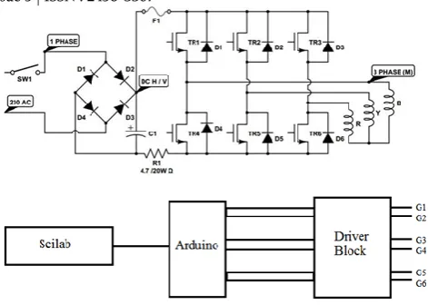
B. Power circuit design
The power circuit designed contains full bridge rectifier with split capacitors assembly, full bridge inverter assembly. Single phase 230V, 50Hz AC supply is applied to the full bridge rectifier and IGBT. IGBT switches are protected against surge voltages using snubber circuit. This full bridge rectifier converts single phase AC input into DC which is filtered by capacitor. The pure DC supply is applied to the full bridge inverter which is made up of six IGBT switches. The output of the 3-phase inverter is given to induction motor. The energy that a switching power converter delivers to a motor is controlled by Pulse Width Modulated (PWM) signals applied to the gates of the switches. PWM signals are pulse trains with fixed frequency and magnitude and variable pulse width. The power circuit design is shown in figure 2.
Figure 2- Power circuit diagram
C. Driver Circuit Block
The FAN 7392 is a monolithic high and low side gate driver IC, that can drive high speed MOSFET and IGBTs that operate up to +600V it has a buffered output stage with all NMOS transistors designed for high pulse current driving capability and minimum cross conduction. This processes high voltage and common mode noise cancelling techniques provide stable operation of the high side driver under high dv/dt noise circumstances. An advanced level shift circuit offers high side gate driver operation up to VS=9.8V (typical) for
VBS=15V. Logic inputs are compatible with standard
CMOS or LSTTL output, down to 3.3V logic. The high current and low output voltage drop feature makes this
device suitable for half and full bridge inverters, like switching mode power supply and high power DC-DC converter applications. Figure 3 shows the pin diagram for 14 pin and 16 pin IC. This IC can controls two thyristor gates.
Figure 3- Pin diagram of FAN 7392/7392M
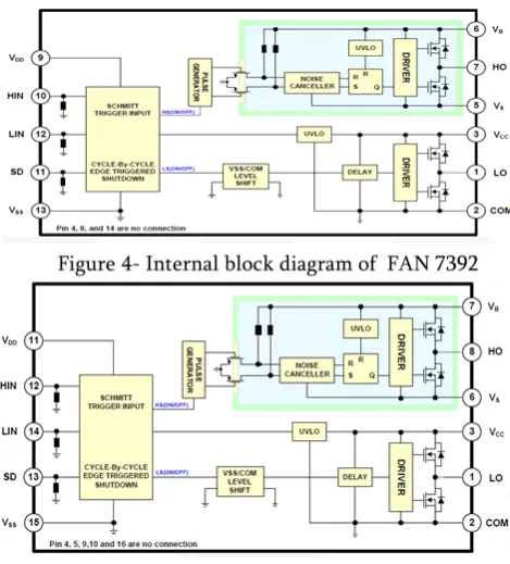
Figure 4 and figure 5 shows the internal block diagram of FAN 7392 and FAN 7392M.
Figure 4- Internal block diagram of FAN 7392
Figure 5- Internal block diagram of FAN 7392M
D. Scilab Simulation
Download the following files from:
HTTPS://ATOMS.SCILAB.ORG/
2. arduino_1.1-1.bin.x64.windows (suitable for your system).
3. toolbox_arduino_v3 (from:
https://github.com/fizcris/Scilab_Xcos_arduin
o_toolbox_david_MPU6050/blob/master/tool
box_arduino_v3/toolbox_arduino_v3.ino
)Load toolbox_arduino_v3 to Arduino software. Also load
serial_0.4.1_5.5-1.bin and
arduino_1.1-1.bin.x64.windows in scilab console window and run the program.
Figure 6- Circuit for generation of PWM
Used tools:
All the tool are taken from the xcos palette.
1. Signal Builder: This is used to generate
triangular waveform of preferred frequency and amplitude. The specification can be changed according to the requirement.
2. Sine wave generator: This generates a sine wave
of preferred frequency and amplitude. The specification can be changed according to the requirement. Here we are giving comparing six sine wave generator at 60° phase angle.
3. Relationalop: This tool compares the triangular wave form and the sine wave which results in PWM.
4. Arduino Setup: Arduino card is choosed and the
port number is setup.
5. Arduino Digital Write Pin: The PWM is given to
the respective Arduino pins.
Figure 6 shows the simulation circuit that generates PWM needed Trigger the IGBT‟s gate.
III.
RESULTS AND DISCUSSION
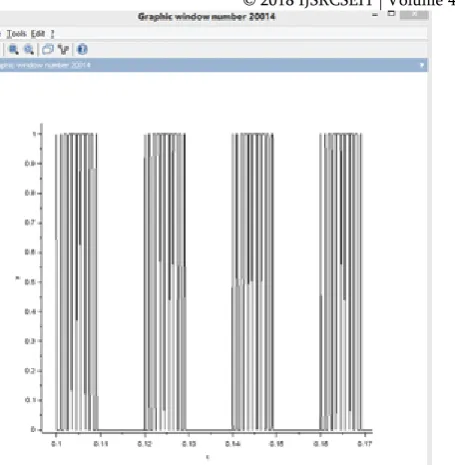
The output of the simulation is shown in figure 7 and 8 that is given to driving circuit which drives the IGBTs at phase difference of 120° for three phase.
© 2018 IJSRCSEIT | Volume 4 | Issue 5 | ISSN : 2456-3307
Figure 8- Generated PWM for negative cycle
We can see a 30° phase shift between positive and negative cycle. The output is shown for single phase. Similarly, three phase PWM can be generated.
IV.
CONCLUSION
Three phase asynchronous induction motors are widely used in industrial applications due to their features of low cost, high reliability and less maintenance. Due to the need for three-phase electricity in today's remote areas for agriculture work where three phase power is not available easily, in those areas these single phase to three phase converters are use full. Operating a three phase induction motor using single phase supply has been presented.
The developed system is useful in remote areas where three phase supply is not available easily.
Applications of single phase to three phase converter are:
Electric Vehicle.
In Irrigation Pumps for Agriculture purpose.
Rural Area Water Supply.
[2].
P. N. Enjeti and A. Rahman, “A new single-phase tothree-phase converter with active input current shaping for low cost ac motor drives,”IEEE Trans. Ind. Applicar., vol. 29, no. 4, pp. 80C813 July/Aug. 1993.
[3].
Shivanagouda.B.Patil, M. S. Aspalli, “OperatingThree Phase Induction Motor Connected to Single Phase Supply”, 2012, International Journal of
Emerging Technology and Advanced
Engineering,(Nov 2012), ISSN 2250-2459.
[4].
M. Khan, I. Husain, and Y. Sozer, “Integratedelectric motor drive and power electronics for bidirectional power flow between the electric vehicle and dc or ac grid,” Power Electronics, IEEE Transactions on,vol. 28, no. 12, pp. 5774–5783, Dec 2013.
[5].
Dong-Choon Lee, Member, IEEE, and Young-SinKim,” Control of Single-Phase-to-Three-Phase AC/DC/AC PWM Converters for Induction Motor Drives,” IEEE TRANSACTIONS ON INDUSTRIAL ELECTRONICS, VOL. 54, NO. 2, APRIL 2007.
[6].
Shivanagouda.B.Patil, M. S. Aspalli,” OperatingThree Phase Induction Motor Connected to Single Phase Supply ,” International Journal of Emerging Technology and Advanced Engineering, ISSN 2250-2459, Volume 2, Issue 11, November 2012.
[7].
Arvind K.Yadav, Nayan Wadgure, Pavan kamdi,“CONVERSION OF SINGLE PHASE TO THREE PHASE SUPPLY” International Journal of Research in Advent Technology (E-ISSN: 2321-9637), “ICATEST 2015”, 08 March 2015.
[8].
M. A. Kumar and S. Lakshminarayanan, "Costeffective gate drive circuit for MLI with constant number of conducting switches," 2016 IEEE International Conference on Recent Trends in
Electronics, Information & Communication