CSEIT1723305 | Received:14 June 2017 | Accepted: 26 June 2017 | May-June-2017[(2)3: 899-904]
International Journal of Scientific Research in Computer Science, Engineering and Information Technology © 2017 IJSRCSEIT | Volume 2 | Issue 3 | ISSN : 2456-3307
899
Voice Controlled Home Automation using Microcontroller
Sandeep Kushwaha, Amrik Singh, Srawan Kumar Chauhan, Sameer Dahate, Nikhil Keshri, Vishal
Goswami
Department of Electronics & Telecommunication Engineering, RSR-Rungta College Of Engineering & Technology, Bhilai, Chandigarh, India
ABSTRACT
Voice Controlled Home Automation is a very useful project for the adults and physically disabled persons, who are not able to do various activities efficiently when they are at home and need one’s assistant to perform those tasks. With the Voice Recognition the complication of wiring in case of wired automation is prevented. With the use of Bluetooth Home Automation considerable amount of power saving is possible and it is flexible and compatible with future technologies so it can be easily customized for individual requirements. Voice recognition system provides secure access to home. In the recent years, the Home Automation systems have seen rapid changes due to introduction of various wireless technologies. Paper presents the overall design of ‘Voice Controlled Home Automation’, which we are currently developing. The automation recognizes voice commands given by the user and transfers it to our microcontroller which detects the voice command and proceeds with the switching accordingly. We are using Microcontroller & Bluetooth module HC05 to implement our vision. Further we are trying to implement the same on a more user friendly and bigger scale. The home automation system is intended to control all lights and electrical appliances in a home or office using voice commands.
Keywords : Microcontroller, Voice Controlled Home Automation , HC05, LCD, MCU, RXD, TXD Signals, Serial Port Protocol
I.
INTRODUCTION
With the advancement of technology, number of equipment and modern household appliances increases to make life easier and comfort. Operating them manually is a tedious job and again hectic sometimes. If one can control devices like TV, fan, light or a music system with a remote from a distance place just by speech recognition, life will become simpler. To switch on or off the devices one has to move to the switch board which is inconvenient even for an able person. If all this manual work is replaced by a voice remote control even the aged and disable person can do the task like a normal person. Much related work has been reported for the same function by different groups with different approaches. Multiple home devices switch can be control with a designed system using microcontroller as heart of the circuit with android based mobile phone. Here the mode of controlling devices is by sending command wirelessly through Bluetooth. Another approach is by GSM based for home automation. This is done by sending short sms
code from a mobile handset. Here it has a wider coverage area. So to control any house hold appliances from a distance place within the network area coverage sending a short sms code will either ON or OFF the devices at home.
through the Bluetooth, corresponding output port will be active which in turn will active the relay and control the appliance. The input pin when remain open has 1.8V but when close it is connected to ground.
II.
DESIGN AND IMPLIMENTATION
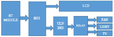
In this project Bluetooth module is interfaced to 8051 microcontroller. In this project we have used 8051 microcontroller for controlling the whole process of this project. And a Bluetooth module is used for controlling the home appliances wirelessly. This Bluetooth receives the commands from the Android application device using wireless communication. The program which is written to the 8051 microcontroller communicates with Bluetooth module serially to receive the commands. Microcontroller switches the electrical loads automatically based on the commands received from the Bluetooth. Circuit connections of this project are very simple. Bluetooth module’s Rx and Tx pins are directly connected to the Tx and Rx pins of Microcontroller. Here at89c51 microcontroller is used. It is an 8 bit microcontroller and it requires supply voltage of 5V DC. Use 7805 power supply circuit to provide 5V DC to the microcontroller. For the above circuit additionally you need to connect reset circuit and crystal circuit to the controller to work properly. Home appliances will turned ON and OFF when user will speak in the Bluetooth mobile app in Android mobile phone. To run this project, first we need to download Bluetooth app form Google play store. We can use any Bluetooth app that can send data using Bluetooth. Remote operation is achieved by any smart-phone or Tablet with Android OS, upon a App voice operation. The transmitting end uses an Android application for the voice commands that are transmitted to digital bits. At the receiver end, these commands are used Serial communication data sent from the Android application is received by a Bluetooth receiver interfaced to the microcontroller. The program on the microcontroller refers to the serial data to generate respective output based on the input data to operate the Relay. Three 5 volt relays are used as a switch for turning On and Off the home appliances running on AC mains shown in figure 1.4. And a relay driver ULN2003 is used for driving relays. Fan, Light and TV are connected at P2.1, P2.2 and P2.3 via relays and relay driver. An 11.0592 MHz Crystal oscillator is used in this circuit for generating clock signal for microcontroller. In the above circuit LCD is used to
indicate the status of electrical loads and also used to display received data from Bluetooth. Here LCD is interfaced to the PORT1 of the microcontroller.
Figure 1 : Block Diagram Of Home Automation
III.
METHODOLOGY
A. BT Module
HC serial Bluetooth products consist of Bluetooth serial interface module and Bluetooth adapter, such as: (1) Bluetooth serial interface module:
Industrial level: HC-03, HC-04(HC-04-M, HC-04-S). Civil level: 05, 06(06-M, 06-S) HC-05-D, HC-06-D (with baseboard, for test and evaluation).
(2) Bluetooth adapter: HC-M4, HC-M6.
This document mainly introduces Bluetooth serial module. Bluetooth serial module is used for converting serial port to Bluetooth. These modules have two modes: master and slaver device. The device named after even number is defined to be master or slaver when out of factory and can’t be changed to the other mode. But for the device named after odd number, users can set the work mode (master or slaver) of the device by AT commands. HC-04 specifically includes: 1. Master device: HC-04-M, M=master
2. Slave device: HC-04-S, S=slaver
The default situation of HC-04 is slave mode. If you need master mode, please state it clearly or place an order for O4-M directly. The naming rule of HC-06 is same. When HC-03 and HC-05 are out of factory, one part of parameters are set for activating the device. The work mode is not set, since user can set the mode of HC-03, HC-05 as theywant. The main function of Bluetooth serial module is replacing the serial port line, such as:
Bluetooth connection is equivalently liked to a serial port line connection including RXD, TXD signals. And they can use the Bluetooth serial module to communicate with each other.
2. When MCU has Bluetooth salve module, it can communicate with Bluetooth adapter of computers and smart phones. Then there is a virtual communicable serial port line between MCU and computer or smart phone.
3. The Bluetooth devices in the market mostly are salve devices, such as Bluetooth printer, Bluetooth GPS. So, we can use master module to make pair and communicate with them. Bluetooth Serial module’s operation doesn’t need drive, and can communicate with the other Bluetooth device who has the serial. But communication between two Bluetooth modules requires at least two conditions: (1) The communication must be between master and slave. (2) The password must be correct. However, the two conditions are not sufficient conditions. There are also some other conditions basing on different device model.
HC-05 module is an easy to use Bluetooth SPP (Serial Port Protocol) module, designed for transparent wireless serial connection setup. Serial port Bluetooth module is fully qualified Bluetooth V2.0+EDR (Enhanced Data Rate) 3Mbps Modulation with complete 2.4GHz radio transceiver and baseband.
B. Microcontroller
The 8051 architecture provides many functions (central processing unit (CPU), random access memory (RAM),read only memory (ROM), input/output (I/O), interrupt logic, timer, etc.) in one package:
8-bit arithmetic logic unit (ALU) and accumulator, 8-bit register (one 16-bit register with special move instruction), 8-bit data bus and 2×16-bit address but/program counter/data pointer and related 8/11/16-bit operations; hence it is mainly an 8-bit microcontroller.
Boolean processor with 17 instructions, 1-bit accumulator, 32 registers (4 bit-addressable 8-bit) and up to 144 special 1 bit-addressable RAM variables (18 bit-addressable 8-bit).
Multiply, divide and compare instructions.
4 fast switchable register banks with 8 registers each (memory mapped).
Fast interrupt with optional register bank switching.
Interrupts and threads with selectable priority.
Dual 16-bit address bus – It can access 2 x 216 memory locations – 64 KB (65,536 locations) each of RAM and ROM.
Two 16-bit Counter/timers.
Power saving mode (on some derivatives).
C. Relay Driver ULN2003
ULN2003 is a high voltage and high current Darlington array IC. It contains seven open collector Darlington pairs with common emitters. A Darlington pair is an arrangement of two bipolar transistors.
ULN2003 belongs to the family of ULN200X series of ICs. Different versions of this family interface to different logic families.Each channel or Darlington pair in ULN2003 is rated at 500mA and can withstand peak current of 600mA. The inputs and outputs are provided opposite to each other in the pin layout. Each driver also contains a suppression diode to dissipate voltage spikes while driving inductive loads.
A Relay driver IC (ULN2003) is an electro-magnetic switch that will be used whenever we want to use a low voltage circuit to switch a light bulb ON and OFF which is connected to 220V mains supply. The required current to run the relay coil is more than can be supplied by various integrated circuits like Op-Amp, etc. High current capacities, capability to stand ESD and drive circuit isolation are the unique properties of Relays. ULN2003 is also commonly used while driving Stepper Motor Refer Stepper Motor Interfacing Using ULN2003.
There are some feature of ULN2003 given below: 1. 500-mA-Rated Collector Current (Single Output)
2. High-Voltage Outputs: 50 V
3. Output Clamp Diodes
4. Inputs Compatible with Various Types of Logic
A relay is an electrically operated switch. Many relays use an electromagnet to mechanically operate a switch, but other operating principles are also used, such a solid state relays.
A type of relay that can handle the high power required to directly control an electric motor or other loads is called a contactor. Solid-state relays control power circuits with no moving parts, instead using a semiconductor device to perform switching. Relays with calibrated operating characteristics and sometimes multiple operating coils are used to protect electrical circuits from overload or faults; in modern electric power systems these functions are performed by digital instruments still called "protective relays".
Magnetic latching relays require one pulse of coil power to move their contacts in one direction, and another, redirected pulse to move them back. Repeated pulses from the same input have no effect. Magnetic latching relays are useful in applications where interrupted power should not be able to transition the contacts.
E. LCD
LCD is used to indicate the status of electrical loads and also used to display received data from Bluetooth. In this project LCD is connected to the microcontroller and microcontroller communicate with Bluetooth module then command from Bluetooth will display in LCD display.
LCD stands for liquid crystal display. Character and graphical lcd's are most common among hobbyist and diy electronic circuit/project makers. Since their interface serial/parallel pins are defined so its easy to interface them with many microcontrollers. Many products we see in our daily life have lcd's with them. They are used to show status of the product or provide interface for inputting or selecting some process. Washing machine, microwave, air conditioners and mat cleaners are few examples of products that have character or graphical lcd's installed in them.
All lcd consist :
Eight(8) data pins D0-D7
Vcc (Apply +5 volt here)
Gnd (Ground this pin)
Rc (Register select)
Rw (read - write)
En (Enable)
V0 (Set Lcd contrast)
IV.
RESULT
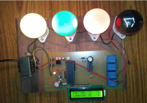
We have perform the home automation control through BT module which consist a AMR Voice BT control Android App, HT05 Module, Microcontroller, ULN2003 Relay driver IC, LCD, four Relays, Resistances and LEDs etc.
In this performance, we have two section first one is Transmitter section(as a remote) and second one is Receiver section(connected to load). In transmitter section signal is transmitter by sending Voice command and signal is received by receiver through the BT Module which is connected to the microcontroller and use relay driver IC to control the corresponding load, like- tv, fan, ac, tube light etc.
As compared to the RF module, it coverage area is same but it is more applicable for the physical handicapped, paralysed and aged people who is not able to walk long distance.
Analysis and Discussion
Better Performance compared to other methods: This method is more effective as compared to other method due to some following points given below:
The range of BT module is large as compared to other module theoretically 100 m but practically it is about 20m-30m.
For e.g. The range of IR module is very less than the BT module and BT module preferred more than the IR module.
IR module can work only in line of sight so it will not work when any obstacle present between transmitter and receiver but BT module can work even in the present of obstacle.
Figure 2 : Complete Voice Control Home Automation
V.
CONCLUSION
Home automation is undeniably a resource which can make a home environment automated people can control their electrical devices via these. Home automation device and setup controlling actions through Voice. In future the product may have high potential for marketing. Further it can be demonstrated from computer instead of android for controlling home appliances of any larger place like industries, hospitals, institution etc. Although we succeed in making this project, but we have faced several challenges while making this project. First of all we had gone through lots of difficulties in finding the components and ICs. When finally we find all the components and ICs. We made the projects taking reference from lots of books and internet, Wikipedia and from our faculty members. The access to the home appliances can be control manually. The system integration is based on wireless control. The home appliances devices can be easily control by the user through Voice remote control. Voice Controlled Home Automation is a very useful project for the adults and physically disabled persons, who are not able to do various activities efficiently when they are at home and need one’s assistant to perform those tasks.
VI.
FUTURE WORK
In industries, there will be various loads to be operated and these loads are to be operated at some specific intervals according to our requirements and also based on the device’s constraints. For these purposes, a person should be employed to monitor the status of the loads. But there may be chances that the person may
forget to operate these loads. And also it is not an easy task for a person to operate these loads manually as these loads run with high currents and high power consumption. This project gives the best solution for electrical power wastage. Also the manual operation is completely eliminated. This project does this application using wireless concept. One of wireless communication system is Bluetooth communication system as it is very cheap and very easy to implement. This project is not only limited to industrial applications but can also be extended to domestic purposes as voice control home appliances controlling using BT module. The home appliances can be switched on/off using this BT module concept without actually going near the switch boards or regulators.
The loads like lights, motors, heaters, power controlling system and also current through the loads can be controlled in this project. We can control all loads at a time from one place (control room) without connecting any physical wire between loads and control room. The BT modules used here are 2.4GHz UART.
VII.
REFERENCES
[1]. N K Kaphungkui, "BT based Remote Control for Home Electrical Appliances" in International Journal of Innovative in Electrical, Electronics, Instrumentation and Control Engineering, Vol. 3,Issue 7, July 2015.
[2]. Mukesh Kumar and Shimi S.L, "Voice Recognition Based Home Automation System for Paralyzed People" in International Journal of Advanced Research in Electronics and Communication Engineering (IJARECE) Volume 4, Issue 10, October 2015
[3]. Amrutha S, Aravind S, Ansu Mathew, "Speech Recognition Based Wireless Automation of Home Loads" in International Journal of Engineering Science and Innovative Technology (IJESIT) Volume 4, Issue 1, January 2015 [4]. Nidhi Gaur and Shabrinath B.B "Design and
International Journal of Engineering Science & Research Technology.
[6]. Rajesh K R, C A Bindyasashree "Multi Appliances Controlling and Monitoring System Based on Wireless Embedded Home Gateway" in International Journal of Innovative Research in Computer and Communication Engineering, Vol. 3, Issue 4, April 2015.
[7]. http://www.electronicshub.org/bluetooth-controlled-electronic-home-appliances/ [8]. https://www.engineersgarage.com/contribution/h
ome appliances-control-by-human-voice [9]. https://wiki.eprolabs.com/index.php?title=Blueto
oth_Module_HC-05
[10]. http://www.engpaper.com/home-automation-2015.htm