IJEDR1403026
International Journal of Engineering Development and Research (www.ijedr.org)3055
ASIC Implementation of High Throughput PID
Controller
1
Chavan Suyog,
2Sameer Nandagave,
3P.Arunkumar
1,2M.Tech Scholar, 3Assistant Professor School of Electronics Engineering VLSI Division, VIT University, Vellore (India)
________________________________________________________________________________________________________
Abstract - In this paper we implemented the pipelined Proportional Integral Derivative (PID) controller using the ASIC
Implementation. We used Han Carlson adder and pipelined multiplier to design the PID controller which results into the implemented design can be useful to the modern controlling operations which requires low power and improved speed performance. The implemented design is tuned and analyzed with frequency responses for various error coefficients values using the Matlab. The Controller algorithm is simulated and synthesized using Modelsim and Cadence RC Compiler and ASIC Implementation is done with Cadence Encounter tool. The results are compared with the traditional architecture in terms of power, speed and the area.
Index Terms - PID, Han Carlson Adder, ASIC
________________________________________________________________________________________________________
I. INTRODUCTION
Proportional Integral derivative (PID) controllers have been wide used over the last several decades due to their simplicity, robustness, effectiveness and relevance for a broad category of systems. Despite the numerous control style approaches that have appeared within the literature, it is calculable that nowadays PID controllers are still used in additional than 95th of business processes a vital feature of this controller is that it does not require an explicit analytical model of the system that is being controlled and less manual control. for this reason, PID controllers have been wide used in robotics, automation, method control, producing, transportation, and apparently in real time multi tasking applications.
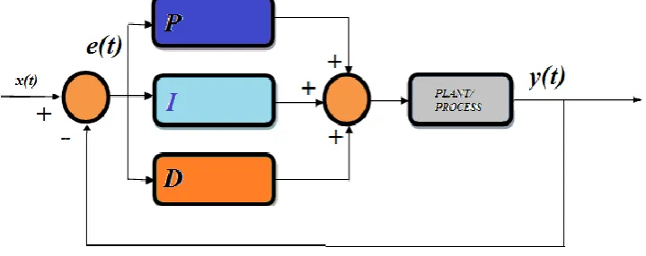
Implementation of digital PID controller has responded to several stages of evolution, from the mechanical form of the the PID controller is now evolved into the compact and digital form. The PID controller is the amalgam of three basic controlling actions called as Proportional (P), Integral (I) and derivative as shown in figure1.
Fig 1 Parallel Form of PID Controller
These controlling actions can be interpreted as representation of various errors in terms of time. Proportional (P) control represents the present errors, Integral (I) control represents the accumulation of past time errors and Derivative (D) control determines the future errors in the system which depends on the current rate of change The algebraic sum of all these controlling action is used to control the process as all are the controlling actions are taking place simultaneously in PID which results into the higher stability and excellent steady state performance.
This Paper has been divided into four sections. First section introduces PID controller with structure and controlling algorithm. In the second section the discrete form of the PID controller has been discussed .In the third section the proposed architecture of PID controller has been discussed. In the fourth section we put the experimental and simulation results along with comparison table II. DISCRETEFORMOFPID
The HDL implementation of continuous form of PID is very difficult as the equation contains derivative and integral terms hence we have to first convert continuous form of PID into discrete form. According to the literature review there are plenty of conversion methods available, here we have chosen the backward difference method to discretize the PID equation.
IJEDR1403026
International Journal of Engineering Development and Research (www.ijedr.org)3056
In the above equation Kp is the proportional gain Ti is the integration time , Td is the derivative time and u(t) is the standard output of PID.The standard parallel form of PID is given by equation 2.Where Ki=Kp/Ti and Kd=KpTd Differentiating both sides of equation (2)
Now applying Backward difference method to above equation
Again applying backward difference method on equation (4)
Solving the equation (5) gives the controller output u(n) in discrete form
Where u(n)=controller output e(n)=Error signal
Ts=Sampling Period of A/D Converter
This is the required discrete form of the PID equation which can be implemented by the HDL languages. III. METHODOLOGY
To design the high throughput PID controller it is essential to chose the transfer function of the system or a plant process and tune the PID to appropriate values of error coefficients Kp,Kd and Ki.PID tuning is the crucial step in the whole PID algorithm.PID controller is fully automated and requires only manual tuning .The PID tuning means changing the values of the error coefficients to get the desired output response .Tuning is done on the trial and error basis by observing the output response.
Matlab Simulation
To find the values of error coefficients and to tune the PID .We used Matlab simulation. First we have chosen the transfer function as
With sampling period TS=0.01 Sec
IJEDR1403026
International Journal of Engineering Development and Research (www.ijedr.org)3057
Fig 2 Matlab Simulation Result of PID TuningImplemented PID Architecture
We implemented the high throughput PID architecture in this paper, the controller algorithm based on discrete form of PID equation uses the values of error coefficients obtained from the Matlab simulation. To get the high throughput we adder two parallel structures namely 20 bit Han Carlson adder and 8 stages pipelined multiplier in the traditional architecture. Due to the parallel processing architecture we got the improved speed performance as compared to the traditional architecture.
Han Carlson adder
This adder is parallel form of the look ahead carry generator. Its algorithm uses tree like structure to do the operations parallel so that we get the high throughput. Nowadays this addition algorithm is popular in Intel Pentium processors because it is area efficient and gives excellent speed performance.
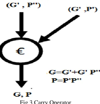
The operation of Han Carlson adder is similar to the Kogge-Stone adder which depends on generation of generate (G) and propagate (P) terms at each stage of addition and adding to the next stage in specific direction. The carry operator is as shown in figure 3
Fig 3 Carry Operator
IJEDR1403026
International Journal of Engineering Development and Research (www.ijedr.org)3058
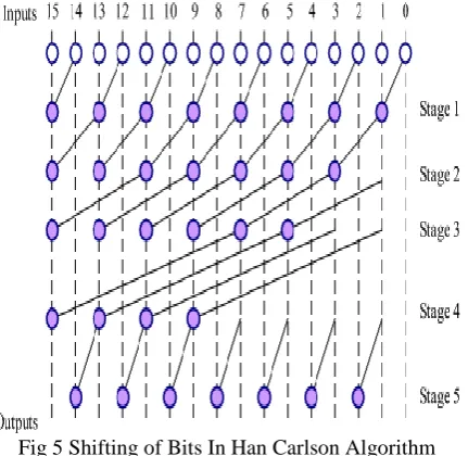
Fig 4 Han Carlson Addition PrincipleThe Han Carlson algorithm uses the parallel processing to improve the speed performance the major difference between Kogge-Stone adder and Han Carlson adder is shifting of bits towards the carry operator in each stage. In Kogge-Kogge-Stone adder the shifting pattern is straight forward but in Han Carlson adder each time shifting of bits to the carry operator follows certain rules .The bit shifting pattern in Han Carlson adder is shown in figure 5.
Fig 5 Shifting of Bits In Han Carlson Algorithm
Pipelined Multiplier
Multiplication is one of the supreme operation in PID controller. Generally multiplication process consumes more power and gives sluggish speed performance due to several addition operations involved in it. Since the multiplier is the slowest data processing element the modern market needs speed improvement. One of the best approaches to improve the speed performance is to implement the pipelining in the design. Pipelining does all the operations concurrently without waiting for completion of other operation.
We implemented 8 stage pipelined multiplier in the PID algorithm. We introduced several registers to store the data. This stored data processed in the parallel form and reduces the number of clock cycles required for the operation. The literature review tells that we can get the double speed of operation with the introduction in the pipelining in the design.
IV. PHYSICALDESIGN
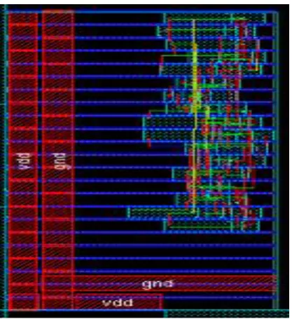
The physical design involves the floorplaning, routing and the creating GDS II file for fabrication. After the successful synthesis we created the physical design using the CADENCE ENCOUNTER tool to create the physical design by following the ASIC design flow we followed the following steps sequentially.
1. Generate the netlist file of the RTL design using 180nm technology library 2. Generate the IO Port mapping file, which has to import in ENCOUNTER. 3. After importing the file in ENCOUNTER generate the floorplan.
IJEDR1403026
International Journal of Engineering Development and Research (www.ijedr.org)3059
7. Check for the timing analysis and generate GDS II file.Fig 6 Physical View of Implemented Architecture using ENCOUNTER V. EXPERIMENTALRESULTS
In this paper we simulated and synthesized using the Modelsim and different types of analysis is performed using Cadence RC compiler. By selecting the different sets of error coefficients we simulated the implemented PID algorithm .One of the simulation result is shown in figure 7.
Fig 7 Simulation Result using MODELSIM
IJEDR1403026
International Journal of Engineering Development and Research (www.ijedr.org)3060
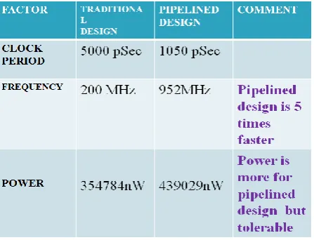
Table 1 Comparison of Traditional and Pipelined ArchitectureVI. CONCLUSION
In this paper we introduced the high throughput parallel architecture of PID controller which uses the Pipelined multiplier and Han Carlson adder. We found that delay has been reduced by considerable amount of time, so we can conclude that use of pipelining and use of parallel prefix adder like Han Carlson adder improves the speed performance of the design. The implemented architecture can be used in automation industries, Power electronics applications and DSP applications and its give improved speed performance as compared to the traditional architectures.
REFERENCES
[1] Yuen Fong Chan M. Moallem “Design and Implementation of Modular FPGA-Based PID Controllers.” IEEE Transactions on Industrial Electronics, Vol.54 (2007).
[2] L Samet, N. Masmoudi, M. W. Kharrat, and L. Kamoun, “A Digital PID controller for real-time and multi-loop control: A comparative study,” in Proc. IEEE International. Conference on Electronic Circuits and Systems., Sep. 1998, vol. 1.
[3] S. L. Jung, M. Y. Chang, J. Y. Jyang, L. C. Yeh, and Y. Y. Tzou, “Design and implementation of an FPGA-based control IC for AC-voltage regulation,” IEEE Transaction on. Power Electronics., vol. 14, no. 3, pp. 522–532.
[4] R. Chen, L. Chen, and L. Chen, “System design consideration for digital wheelchair controller,” IEEE Transaction on. Industrial. Electronics, vol. 47, no. 4, pp. 898–907, Aug. 2000.