IJEDR1303062 INTERNATIONAL JOURNAL OF ENGINEERING DEVELOPMENT AND RESEARCH | IJEDR Website: www.ijedr.org | Email ID: [email protected] 310
Orthogonal Frequency Division Multiplexing
Technique
1
Komal Harvani,
2Arjav Bavarva
1M.E. Student, 2Assistant Professor
Electronics & Communication Department, RK University , Rajkot, India 1
[email protected]
,
2[email protected]
Abstract— over the past few years, there has been increasing emphasis on extending the services available on wired public
telecommunications networks to mobile non wired telecommunications users. At present, for mobile network users only low-bit-rate of 100 to 150 kbps data services are available. However, demands for wireless broadband multimedia communication systems (WBMCS) are increasing. It is necessary to use high-bit-rate transmission of at least several MBPS for upcoming new technologies. If digital data is transmitted at the rate of several MBPS, the delay time of the delayed waves is greater than 1 symbol time. Using one of the probably solution for adaptive equalizing signal. There are practical difficulties in operating this equalization at several megabits per second with compact, low-cost hardware. To overcome such an issue and to Achieve WBMCS. Orthogonal frequency division Multiplexing (OFDM) Apply to parallel-data transmission scheme, which reduces the influence of multipath fading and makes complex equalizers unnecessary.
INDEX TERMS—OFDM,WBMCS,ORTHOGONAL,ADC
I.OFDMBASICS
Basic concept of using a large number of parallel narrow-band subcarriers instead of a single wide-band carrier to transport information OFDM is a multi-carrier transmission technique, which divides the available spectrum into many Subcarriers, each one being modulated by a low Data rate stream it uses serial to parallel conversation scheme as shown in figure
The employment of discrete Fourier transform to replace the banks of sinusoidal generator and the demodulation significantly reduces the implementation complexity of OFDM modems At Receiver Side
Figure 1 Serial to Parallel [2] IV. OFDM System Design
Orthogonal frequency division multiplexing (OFDM) is a specialized frequency multiplexing (FDM) technique. It divides total available bandwidth into a number of orthogonal sub-carriers and simultaneously transfers signals on these sub-carriers with a low data rate, achieving a total data rate approaching ideal Nyquist data rate. Lower data rate on each sub-carrier means narrower bandwidth, which brings several benefits to the data transmission, such as flat channel fading and simpler receiver design.
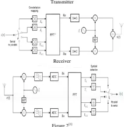
An idealized OFDM communication system model can be shown as Figure 1. [1] In the transmitter, the signal source, a serial binary sequence, is first de multiplexed into multiple parallel data streams, corresponding to the number of sub-carriers to use. Each produced stream is performed with constellation mapping, i.e. modulated with a certain modulation scheme (e.g. BPSK).Then an inverse FFT is applied to each set of mapped symbols to convert them into time-domain samples.
IJEDR1303062 INTERNATIONAL JOURNAL OF ENGINEERING DEVELOPMENT AND RESEARCH | IJEDR Website: www.ijedr.org | Email ID: [email protected] 311 Transmitter
Receiver
Figure 2[1]
IEEE Standard comparison
[1]IEEE 802.11a
54 Mbps
For example, an 802.11a network, which broadcasts on the 5GHz frequency band, supports 12 simultaneous channels (in North American).
Maximum data rate 12*54=648 Mbps.
[2]IEEE 802.11b
11Mbps
For example, a standalone 802.11b network supports three non-overlapping channels (worldwide), each with a peak data rate of 11 Mbps.
Maximum data rate 3*11=33 Mbps.
[3]IEEE 802.11g
54 Mbps
For example, an 802.11g installation supports three channels, each with a peak rate of 54 Mbps.
Maximum data rate 3*54=162 Mbps.
V TIMGING OFFSET ESTIMATORS
The boundary of preamble and the frequency offset will be estimated by timing and frequency synchronization algorithms respectively and then the OFDM symbols inside the frame needs to be compensated for the frequency offset before carrying out demodulation. Using Following Methods
[1] Schmidl’s method
Two training symbols are placed at the beginning of each frame as preamble. Here, the sequence used to generate the training sequence should be chosen on basis of having a low peak-to-average power ratio so that there is little distortion in the transmitter amplifier
Table 1 PAPR Comparison
IJEDR1303062 INTERNATIONAL JOURNAL OF ENGINEERING DEVELOPMENT AND RESEARCH | IJEDR Website: www.ijedr.org | Email ID: [email protected] 312 [2] Minn’s method
Based on Schmidl & Cox method, Minn method modified the training sequence’s pattern and timing metric’s definition and designed the first training symbol having four parts with following patterns
where A represents samples of length L = N / 4 generated by N / 4 point IFFT of / 4 c N length modulated data of a PN sequence. The timing metric used in the evaluation of the technique is given by
Where k r is the received signal, and d is a time index Corresponding to the first sample in a sliding window of 4L samples [3] Park’s method
Minn’s method reduces the timing metric plateau found in Schmidl’s method but the MSE is still large particularly in ISI channels. This is resulted from the timing metric values around the correct timing point in Minn’s method are almost the same. Park method proposed to increase the difference between the peak timing metric with respect to other metric values.
The proposed method entails modifying the training sequence’s pattern and timing metric’s definition to maximize the different pairs of product between them. The first training symbol having four parts with the following patterns:
Where A represents samples of length L = N / 4 generated by IFFT of a PN sequence. B is designed to be symmetric with A. A* and B * are conjugate of A and B respectively. The timing metric is given by following equation.
IJEDR1303062 INTERNATIONAL JOURNAL OF ENGINEERING DEVELOPMENT AND RESEARCH | IJEDR Website: www.ijedr.org | Email ID: [email protected] 313 VI SIMULATION RESULTS
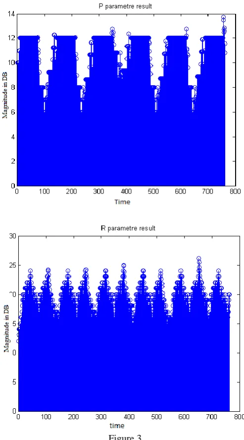
In this section, the proposed algorithm shows the estimation Performances for OFDM signals in P & R Parameter. The simulations were performed for the base-band model of signals. Data symbols are modulated with each carrier The estimation performances with varying parameters of System Channels in shifted data are shown below. correct estimation probability in the graph indicates the proposed algorithm exactly estimating each parameter. From the result, P & R is recognized with 100% probability.
Figure 3
The reason is that many prefix symbols implemented in the frame featured a comparatively tough peak for the estimation, as shown in Figure.
Estimation performances for the other parameters are affected by the value of this Parameter. Here the Proposed algorithm seeks for the other parameters by using the Results identified in previous steps.
The performances added to both Parameters are shown in Figure. VII WHY OFDM OFDM possesses some inherent advantages for Wireless Communications [1]Multi-path Delay Spread Tolerance
The increase in the symbol time of the OFDM symbol by N times (N being the number of sub-carriers), leads to a corresponding increase in the effectiveness of OFDM
[2]Effectiveness against Channel Distortion
IJEDR1303062 INTERNATIONAL JOURNAL OF ENGINEERING DEVELOPMENT AND RESEARCH | IJEDR Website: www.ijedr.org | Email ID: [email protected] 314 that use single-carrier transmission, an equalizer might be required to mitigate the effect of channel distortion In OFDM systems on the other hand, since the bandwidth of each sub-carrier is very small, the amplitude response over this narrow bandwidth will be basically flat (of course, one can safely assume that the phase response will be linear over this narrow bandwidth). Even in the case of extreme amplitude distortion, an equalizer of very Simple structure will be enough to correct the distortion in each sub-carrier.
[3]Throughput Maximization & Latency minimization
The capacity of transmitting data packet per second will increase and times from transmitter to receiver for one packet will decrease the symbol duration of the OFDM Symbol, it can be possible to change and according to Symbol duration latency and through put will vary
[4] Robustness against Impulse Noise.
Impulse noise is usually a burst of interference caused usually caused in channels such as the return path HFC (Hybrid-Fiber-Coaxial), twisted-pair and wireless channels affected by atmospheric phenomena such as lightning etc.
symbol duration of an OFDM signal is much larger than that of the corresponding single-carrier system and thus, it is less likely that impulse noise might cause (even single) symbol errors. Thus, complicated error-control coding and interleaving schemes for handling burst-type errors are not really required for OFDM Systems simplifying the transceiver design.
[5] Frequency Diversity.
OFDM is the best place to employ Frequency Diversity. In fact, in a combination of OFDM and CDMA called the MC-CDMA transmission technique. frequency diversity is inherently present in the system.
VIII . THE PEAK POWER PROBLEM IN OFDM
One of the most serious problems with OFDM transmission is that, it exhibits a high peak-to-average ratio. In other words, there is a problem of extreme amplitude excursions of the transmitted signal. The OFDM signal is basically a sum of N complex random variables, each of which can be considered as a complex modulated signal at different frequencies. In some cases, all the signal components can add up in phase and produce a large output and in some cases, they may cancel each other producing zero output.
Thus the peak-to-average ratio (PAR) of the OFDM system is very large. The problem of Peak-To-Average Ratio is more serious in the transmitter. In order to avoid clipping of the transmitted waveform, the power-amplifier at the transmitter frontend must have a wide linear range to include the peaks in the transmitted waveform.
Building power amplifiers with such wide linear ranges is a costly affair. Further, this also results in high power consumption. The DAC’s and the ADC’s must also have a wide range to avoid clipping.
IX. Application [1] DAB & HDTV
DAB is a digital Audio Broadcasting and HDTV is a High-definition Television digital technology offering considerable Advantages over today's FM radio & Television, both to entertainer and broadcasting.
[2] Wireless LAN
IEEE 802.16 broadband wireless access system
A typical BWA network supports connection to many user premises within a radio coverage area.
The IEEE 802.16 standard should provides the solution to access systems based on DSL, cable, and eventually fiber optics.
Table 2[3]802.16 bit rate and channel size
IEEE 802.20 mobile broadband wireless access
IJEDR1303062 INTERNATIONAL JOURNAL OF ENGINEERING DEVELOPMENT AND RESEARCH | IJEDR Website: www.ijedr.org | Email ID: [email protected] 315 Table 3 [3] 802.20 bit rate and channel size
X . CONCLUSION
Comprehensive literature in OFDM Application area is presented in this paper. Corresponding Synchronization results are also given for their performances evaluation. Further, a simple but efficient FFT-based frequency estimator is Available as shown in OFDM System Design section, using Gaussian channel and Multipath fading channel we can Vary Symbol time and using Symbol Time latency will minimize and throughput will increase. Among of three Park’s, Minn’s and Schmidl’s methods Minn’s method is better. As an overall performance for minn’s method gives the best Result.
REFERENCES
[1] Fan Wu and Mosa Ali Abu-Rgheff ―Time and Frequency Synchronization Techniques for OFDM Systems operating in Gaussian and
Fading Channels‖ Mobile Communications Network Research School of Computing, vol. 2 issue 1, pp. 52–55, April 2005
[2] Orthogonal Frequency Division Multiplexing for Wireless Networks - ANÍBAL LUIS INTINI [3] OFDM For Wireless communication System - Ramjee Prasad
![Figure 1 Serial to Parallel [2]](https://thumb-us.123doks.com/thumbv2/123dok_us/8606719.1396427/1.595.172.425.431.555/figure-serial-to-parallel.webp)
![Table 3 [3] 802.20 bit rate and channel size](https://thumb-us.123doks.com/thumbv2/123dok_us/8606719.1396427/6.595.178.430.72.184/table-bit-rate-channel-size.webp)
