Morphological Image Processing
Jagtap Sharadkumar,Vice Principal,
Shivaji Mahavidyalaya,Udgir.
Kamble Suvarna,Astt. Professor,
Shivaji Mahavidyalaya,Udgir.
ABSTRACT
This paper presents an Morphological image processing is constructed with
operations on sets of pixels. Binary morphology uses only set membership and is different to the different values such as image, color of a pixel. We will examine some basic set operations and their usefulness in image processing and we will deal here only with Morphological filtering operators such as Erosion , dilation ,Opening , closing Hit-or-miss Boundary extraction . Morphological operations for binary images and its applications.
Keywords: Closing, Dilation, Erosion, Filtering, Opening.
I. INTRODUCTION:
The morophological image processing techniques has exploded and they are now used for all kinds of tasks in different areas such as Document handling, signature verification ,Biometrics ,fingerprint verification / identification ,target recognition autonomous vehicles ,traffic monitoring, face detection ,face receognition.The word morphology commonly denotes a branch of biology that deals with the form and structure of animals and plants. Therefore, morphological operations are intended to affect the shape of the object. Morophological image processing Started in 1960s by G. Matheron and J. Serra. [1]In this Analysis of form and structure of objects..,Tools/Operations for describing/characterizing image regions and image filtering and Images are treated as sets. Different definitions are used in Different implementations in the image processing programs. The original definition, based on set theory, is made by J. Serra in 1982. [2] Defined for binary images - binary operations (boolean, set-theoretical) Can be used on grayscale images multiple-valued logic operations.
The Goals of morphological operations are Simplified image data, Preserves essential shape characteristics, Eliminates noise, Permits the shape to be identified and optimally reconstructed from their distorted, noisy forms.
II.MATEMATICAL FORMULATION
A is a set in ,
a=(a1,a2) an element of A, a∈ A If not, then a A : null (empty) set
A subset of B : AB Union of A and B : C=A B Intersection of A and B : D=AB Disjoint sets : AB= Complement of A :
Difference of A and B : A-B = {x|x∈A, x B} = A∩
Fig : 1 Reflection and Translation
Need for a reference point. Reflection of B:
= {x|x=-b, for b∈B}
Translation of A by x=(x1,x2), denoted by (A)x is defined as: (A)x = {c| c=a+x, for a∈A}
Fig : 2 STRUCTERING ELEMENT
The structuring element consists of a pattern specified as the coordinates of a number of discrete points relative to some origin. Normally Cartesian coordinates are used and so a convenient way of representing the element is as a small image on a rectangular grid. Below Figure shows a number of different structuring elements of various sizes. In each case the origin is marked by a ring around that point. The origin does not have to be in the center of the structuring element, but often it is. As suggested by the figure, structuring elements that fit into a 3×3 grid with its origin at the center are the most commonly seen type.
Example of structuring element
III. BINARY IMAGES
arithmetic in nature.
The structuring element is said to fit the image if, for each of its pixels that is set to 1 , the corresponding image pixel is also 1.
The structuring element is said to hit, an image if for any of its pixels that is set to 1, the corresponding image pixel is also 1.
IV.MOROPHOLOGICAL FILTERING OPERATORS 1. Dilation and Erosion
A is the image, B is the “structural element”, a mask akin to a kernel in convolution
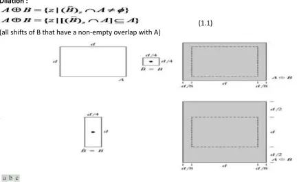
Dilation :
(1.1) (all shifts of B that have a non-empty overlap with A)
Fig . 3 (a) Set A( b) Square structuring element(dot is the center) (c) Dilation of of A by B shown shaded d) Elongated structuring element e) Dilation of A by using this element
Example of Dilation
Fig 4: (a) Sample text of poor resolution with broken characters (magnified view) (b) Structuring
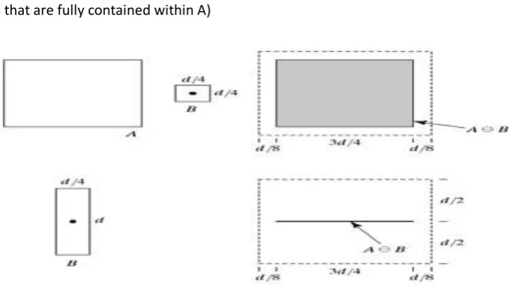
Erosion :
(1.2) (all shifts of B that are fully contained within A)
Fig . 5 (a) Set A( b) Square structuring element (c) Erosion of A by B shown by shaded region d) Elongated structuring element e) Erosion of A by using this element
Example of Erosion
Eroded once Eroded twice 2. Opening and Closing
Opening : smoothes the contour of an object, breaks narrow isthmuses, and eliminates thin protrusions
(2.1)
Fig. 6: Opening:The original image eroded and dilated twice(opened) Most noise is removed
Closing : smooth sections of contours but, as opposed to opning, it generally fuses narrow breaks and long thin gulfs, eliminates small holes, and fills gaps in the contour
Fig.7: Closing: The original image dilated and then eroded.Most holes are filled. Morophological Opening and closing
Fig.8:The structuring element is the small circle shown the dark dot is the center of the structuring element
3.
Hit-or-Miss TransformThe structural elements used for Hit-or-miss transforms are an extension to the ones used with
dilation, erosion etc. The structural elements can contain both foreground and background
pixels, rather than just foreground pixels, i.e. both ones and zeros. The structuring element is
superimposed over each pixel in the input image, and if an exact match is found between the
foreground and background pixels in the structuring element and the image, the input pixel
lying below the origin of the structuring element is set to the foreground pixel value. If it does
not match, the input pixel is replaced by the boundary pixel value.
The hit-or-miss transform is defined as:
Let B ={B1, B2}, where B1 is the set formed from elements of B associated with an object and B2
is the set of elements of B associated with the corresponding background, where B1 and B2 are
(3.1)
Fig.9: ( a) Set A (b) A window W and the local background of X with respect to W ,(W-X).( c) Complement of A (d) Erosion of by (W-X). (f) Intersection of (d) and (e). Showing the location of the origin of X. as desired
Where : object rejected = background related
4.
Boundary ExtractionThe boundary of a set X is obtained by first eroding X by structuring element K and then taking
the set difference of X and it’s erosion. The resultant image after subtracting the eroded image
from the original image has the boundary of the objects extracted. The thickness of the
boundary depends on the size of the structuring element.
Fig.10 : a) Set A( b) Square structuring element B (c) A is eroded by B d) boundary given by the set difference between A and its origin
Conclusion
Mathematical morphology is an approach for processing digital image based on its shape. Using simple mathematics it is possible to perform various operations on images such as Erosion, Dilation, opening, closing, Hit or Mass, boundary Extraction. Post processing uses morphological operators. Same as convolution only use Boolean operators instead of multiply and add. Erosion clears noise, makes smaller. Dilation fills in holes, makes larger.
References:
[1] Georges. Matheron and Jean Serra," History of Mathematical Morphology" published
, in ISMM ,Xerox Center Palo-Alto, june 2000
[2] " Image Analysis and Mathematical Morphology, “Jean Serra, 1982.
[3] "Image Analysis and Mathematical Morphology", Volume2: Theoretical Advances,
Jean Serra, 1988.
[4] "An Introduction to Morphological Image Processing”, Edward R. Dougherty, 1992
[5] "Morphological Image Analysis, “Principles and Applications, Pierre Soille, 1999
[6] R. C. Gonzalez, R. E. Woods, "Digital image processing", 2nd ed. Upper Saddle River, N.J. Prentice Hall, 2002.
[7] "Image processing and analysis – variational PDE", wavelet by Tony F. Chan and Jackie (Jianhong) Shen, 2005