Volume 2006, Article ID 40264, Pages1–7 DOI 10.1155/WCN/2006/40264
Robust OFDM System with ml-HIM Encoding
M. J. Dehghani
Department of Electrical Engineering, Shiraz University of Technology, Modarres Boulevard, P.O. Box 313, Shiraz 71555, Iran
Received 10 April 2006; Revised 16 July 2006; Accepted 22 September 2006
Recommended for Publication by Mischa Dohler
Differential encoding is a widely used technique in the context of orthogonal frequency division multiplexing (OFDM) as an alternative to coherent channel estimation and equalization. In this paper, the performance of differential encoding using a multilag higher-order instantaneous moment (ml-HIM) in OFDM system is investigated. It is shown that by using proper order and lags, the ml-HIM decoder is capable to make a robust system against the phase distortion and the intercarrier interference (ICI) caused by phase distortion and frequency offset.
Copyright © 2006 M. J. Dehghani. This is an open access article distributed under the Creative Commons Attribution License, which permits unrestricted use, distribution, and reproduction in any medium, provided the original work is properly cited.
1. INTRODUCTION
OFDM systems have generated a lot of interest in diverse digital communication applications. This has been due to favorable properties such as high spectral efficiency by al-lowing overlap, robustness against intersymbol interference (ISI) and resistance to impulse noise, ability to dynami-cally optimize the rate to the channel specifications and high computational efficiency by using the fast Fourier transform (FFT) technique to implement the modulation and demod-ulation functions [1]. The OFDM has also been exploited for wideband data communication over mobile radio fre-quency modulation (FM) channels, asymmetric digital sub-scriber lines (ADSL), very high data digital subsub-scriber lines (VDSL) [2], and digital audio broadcasting (DAB) [3].
While inherently robust against multipath fading, OFDM has some disadvantages with respect to single carrier systems. In particular, it has a larger peak-to-average signal power ratio than single carrier modulation and a correspondingly larger sensitivity to nonlinear distortions in a high power am-plifier [4]. In addition, it exhibits serious degradations when the carrier frequency offset is not accurately estimated and compensated [5,6]. Phase ambiguity and/or frequency er-rors are likely to be present in the received signal due to im-perfect knowledge of the frequency and phase of the carrier, fading effects, or multipath propagation. Typically, phase dis-tortions are captured in the term ejθc(t), which multiplies
the received baseband signal. When phase variations are in-duced by the relative motion between the transmitter and the
receiver (such as in mobile and satellite communications), the phaseθc(t) is a polynomial in terms of continuous time
t, and its coefficients are related to the kinematics of the mov-ing station [7].
As an alternative to modeling and estimating phase dis-tortions, phase errors can be precompensated by differential encoding and decoding. Currently, differential encoding is used in the context of OFDM as an alternative to coherent channel estimation and equalization. The European digital audio broadcast (DAB) standard employs differential encod-ing [3]. Although tolerant to constant phase errors, diff eren-tial detection systems are sensitive to carrier frequency vari-ations. To overcome this problem, doubly differential phase shift keying (DDPSK) in single carrier modulation has been introduced [8]. Since in applications such as low earth or-biting (LEO) satellite communications [9], the Doppler fre-quency also changes with time, these approaches are not suf-ficient for compensation. Algorithms for frequency and fre-quency rate-of-change estimation are proposed [10], based on Lanczos FIR differentiators, but they suffer from non-negligible estimation bias. Generalizations to higher-than-second-orderM-ary DPSK have also been suggested in [11]. An interesting approach to carrier frequency and synchro-nization acquisition has been proposed for OFDM systems [12], which is tolerant to time-variant Doppler frequency.
MPSK
un ml-HIM
encoder
an
S/P ... IDFT ... P/S bk
D/A g(t)
(a)
r(t) Matched filter
rk
S/P ... DFT ... P/S
ym
ml-HIM decoder
yk,m
Decision device
un
(b)
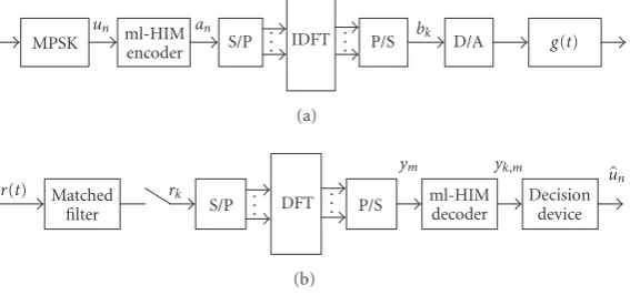
Figure1: Functional block diagram of the considered OFDM on differential encoding (ml-HIM) over adjacent subcarriers: (a) transmitter, (b) receiver.
[14]. In this paper, we propose to incorporate ml-HIM en-coding and deen-coding in an OFDM system to combat not only carrier frequency offset and phase offset, but also other phase distortions. We have applied multilag HIM in the frequency domain as differential encoding and decoding over adjacent subcarriers to PSK signaling in the OFDM transceiver. In or-der to simulate a distortion phase in transmission signal, we have provided a nondispersive channel. We have shown that, in comparison to conventional differential encoding (DPSK), the degrees of freedom offered by the different lags in the ml-HIM technique are able to make robust against the in-tercarrier interference (ICI) caused by phase distortion. To improve the performance of the system, we can concatenate the proposed system with error-correcting coding or turbo codes (TCs), which for simplicity have been excluded from the proposed system.
This paper is organized as follows: inSection 2, we re-view the main features of OFDM and consider the relation-ship between the information and the transmitted symbols with phase ambiguity or phase distortion due to imperfect knowledge of the carrier’s phase and frequency. Section 3
reviews multilag HIM encoding and decoding in a general case forM-ary PSK.Section 4applies ml-HIM as a diff eren-tial encoding to an OFDM system in the frequency domain and derives some expressions for the received signal in diff er-ent situations. In the same section, we have investigated the system performance in terms of ml-HIM lags or delays and have determined proper lags through computer simulation. InSection 5, results and conclusions are presented.
2. SYSTEM OUTLINE
Figure 1shows the baseband functional block diagram of the OFDM transceiver which is considered in this paper. The dif-ferential or ml-HIM encoding can be applied over adjacent OFDM symbols, or over adjacent subcarriers (as shown in
Figure 1(a)), or both methods can be combined [15]. The incoming serial binary data is first grouped intob-bits and each group is converted into a complex number by using the signal constellation, say, for example, multiphase shift keying (MPSK,b=log2M). The complex symbols are differentially
encoded, converted from serial to parallel, given guard inter-val insertion to avoid intersymbol interference (ISI) by mul-tipath distortion, and modulated in a baseband fashion by the IDFT. Each block of frequency-domain symbols is used to produce a corresponding block of channel symbols bk,
k=0, 1,. . .,N−1, through an IDFT, as follows:
bk=√1
N
N−1
n=0
anej2πkn/N, k=0, 1,. . .,N−1. (1)
The symbols are converted back to serial data and then passed through the transmission filter, whose impulse re-sponse g(t) depends on the characteristics of the channel, particularly on channel spacing. By a proper choice of time origin, the complex envelope of the signal transmitted in the generic block can be written as [12]
x(t)= N−1
k=0 bkg
t−kTs
, (2)
whereTsis the symbol period. The receiver performs the re-verse function of the transmitter (Figure 1(b)). In the pres-ence of a distorting phase between the carrier frequency and the local oscillator, the received signal under the assump-tion of ideal frame recovery after baseband conversion (not shown) is [12,14]
r(t)=x(t)ejθc(t)+w(t), (3)
whereθc(t) models the composite phase error introduced by the channel and the imperfect knowledge of the frequency and phase of the carrier; andw(t) is the additive white Gaus-sian noise (AWGN) with two-sided normalized power spec-tral densityN0/2PswherePsandN0denote the average signal
power and noise power, respectively. Suppose a second-order approximation represents an accurate model ofθc(t), such that [14]
θc(t)=θ0+ 2π fdt+παdt2, (4)
model (3) holds, provided that Doppler frequency and the Doppler rate are small when compared to the symbol rate, which is a condition satisfied in many practical cases [14]. After matched filtering, we assume that the signal is sampled, and the sampler output is written as
rk=bkejθk+nk, k=0, 1,. . .,N−1, (5)
whereθkis given by
θk=θ0+ 2π fek+παek2, k=0, 1,. . .,N−1. (6)
Here,θk =θ(kTs),rk =r(kTs), fe = fdTs,αe = αdTs2, and
nkrepresents zero-mean complex Gaussian noise with inde-pendent real and imaginary components, each of variance
N0/2PsTs. The signalrkis then fed to the DFT block, yielding noise with the same statistics asnk. The signal ym can be expressed as a sum of the desired signalCm, the two unde-sired signals, the ICI signalIm, and noise signalηm, that is,
The desired signal valueCmdepends only on the signal trans-mitted on subcarrier m, while Im depends on the signals transmitted on the other subcarriers. The sequence{ym}is in turn applied to a differential detector or ml-HIM decoder whose output drives the decision device.
3. DIFFERENTIAL ENCODING WITH MULTILAG HIM
The multilag HIM technique can be applied to constant modulus constellations, such as MPSK, as well as to generic (nonconstant modulus) constellations, such asM-ary QAM. For the application of the ml-HIM technique toM-PSK sig-naling, let us assume the information symbols um = ejϕm to be independent and identically distributed (i.i.d.), drawn from a discreteM-ary equiprobable PSK alphabet. The ml-HIM encoder converts the information sequence{um}into
un an
Figure2: Second-order ml-HIM: (a) encoder, (b) decoder.
{am}, while the received noisy signal{ym}is decoded by the appropriate ml-HIM decoder. The first-order ml-HIM en-coding and deen-coding, respectively, are specified as [14]
am=umam−m1, (10a)
and the third order as
am=umam−m1am−m2am−m3a
wherewl,m is the output of thelth-order ml-HIM decoder, (·)∗ denotes complex conjugation, andm1,m2,m3are lags
or delays. To ensure causality, we select 1≤m1≤m2≤m3.
We illustrate the second-order ml-HIM encoder and decoder inFigure 2.
To remove anLth-order polynomial phase distortion, we must use an (L+ 1)th-order ml-HIM system [14,16]. There-fore, to remove a constant phase ambiguity, it is sufficient to use a first-order ml-HIM system for encoding and decoding. The second-order ml-HIM system can suppress the effect of both the constant phase and Doppler frequency, while the third-order ml-HIM performs likewise with second-order phase distortion.
In all cases, the receiver chooses that symbolum, which is closest to the noisy estimatewl,m ofum, that is, the decision rule (ML) is given by
um=argmin um
um−wl,m, (13)
where argmin (·) yields the argument for which the given expression achieves the global minimum.
4. SIMULATION DETAILS AND RESULTS
assumed a binary PSK constellation in all the cases with av-erage signal power ofE{|um|2}and complex AWGN noise with independent zero-mean real and imaginary compo-nents, each of varianceσ2/2. The BER performance is
mea-sured for several values of the signal-to-noise ratios (SNRs), which are defined asE{|um|2}/σ2withumhaving unit mag-nitude. To obtain the results for a target BER of 10−4, we
have used Monte-Carlo simulation technique with 105
sym-bols for each set of lags.
4.1. First-order ml-HIM for removing
carrier phase offset
Consider the case ofM-ary PSK signaling as inSection 2. As-sume that the phase distortion in (6) has order zero, that is,
fe = 0,αe = 0, and thenθk = θ0, with the assumption of
ideal carrier recovery. In this case, the encoding and decod-ing strategy is given by (10a) and (10b), respectively. Substi-tutingθk=θ0in (8), the received signal has the simple form
ym=amejθ0+ηm, m=0, 1,. . .,N−1. (14)
Equation (14) shows there is no ICI in the output signal in any subcarrier. The decision is based on the noisy estimate of
um, that is,
whereζ(m1) denotes the disturbance term, which is
ζm1
Whenum is drawn from an MPSK constellation andηm is a zero-mean complex AWGN with varianceσ2, then ζ(m
1)
has zero mean. We define the deflectionDas a performance criterion function in detection as suggested in [14], that is,
D= var
The goal is to find the lagm1that maximizes the deflection
function D. Substituting (15) and (16) in (17), we obtain
D=1/(2σ2+σ4) which is independent ofθ
0andm1.Figure 3
shows the BER performance in terms of SNR forθ0 = π/6
and in terms of the lagsm1=1, 2. As expected, the system has
the same BER performance for different lags. A good choice for the lag ism1 = 1, because it minimizes the number of
symbols required to initialize the differential decoder. In the casem1 =1, the transceiver is the same as standard binary
DPSK applied over adjacent subcarriers in the OFDM sys-tem. According toFigure 3, for a BER of about 10−4, about
0.8 dB of additional SNR is required when the first-order ml-HIM system is used, when compared to the ideal BPSK (with
θ0=0 and fe=0).
4.2. Second-order ml-HIM for removing carrier
phase and frequency offset
Let us consider the phase distortion of order one, that is,
θk=θ0+ 2π fek, which is first-order phase distortion. In this
Figure 3: BER performance of second-order ml-HIM in
BPSK-OFDM in terms of lags: circles (m1 = 1), pluses (m1 = 2). The solid line shows BER in ideal BPSK.
case, we need to apply second-order ml-HIM for encoding and decoding as given in (11a) and (11b), respectively. Sub-stitutingθk=θ0+ 2π fekin (8), we get
on the useful termum, which depends on the ICI, noise, and lags. The deflection function is defined as
D= ECm
Comparison of the received sequence in (18) with (14) shows that the complexity in the ml-HIM of second order is much more than the first-order case. In order to calculate BER and the deflection functionD(m1,m2) and to obtain the optimal
lags (m1,m2), we perform computer simulations. We assume
102
Figure4: (a) Deflection function and (b) BER in second-order ml-HIM in terms of lags. Dash (m1,m2) = (1, 1), circles (1, 2), plus (1, 3). The solid line shows BER for ideal BPSK.
which gives Cm = 0.766um.Figure 4shows the deflection function and BER versus SNR for different lags (m1,m2) =
(1, 1), (1, 2), and (1, 3). The results show that by selecting proper lags, good BER performance can be achieved. In com-parison, it can be seen that except for (m1,m2)=(1, 1), the
values of the deflection functions and BERs for the other pairs of lags are equivalent. According to our results, the pair (1, 1) which corresponds to DDPSK [8], is the worst in terms of BER performance. Considering the memory saved dur-ing initialization, (m1,m2)=(1, 2) is a good choice for this
ml-HIM encoder/decoder. In this case, for a BER of 10−4,
about 3.5 dB additional SNR is required when compared to the ideal BPSK, withθ0=0 and fe=0.
In order to investigate the effect of ICI on the system performance, we consider a noiseless environment, that is,
ηm = 0, and focus on the contribution of ICI. The out-put sequence of the decoder is given by (19), where the
disturbance term ζ(m1,m2) is the ICI. Thus the deflection
functionDbecomes the carrier-to-interference power ratio (CIR) in this case. As expected, the simulation shows that the CIR of the ml-HIM system with lags (m1,m2) = (1, 2)
at 17.5 dB is 2.5 dB more than the CIR in the system with lags (m1,m2)=(1, 1).Figure 4(a)shows the deflection
func-tions for the different lags, where the CIR corresponds to the asymptotic values of these functions as SNR tends to infinity.
4.3. Third-order ml-HIM for removing
second-order phase distortion
In this case, we use the phase distortion given in (6), that is,θk =θ0+ 2π fek+παek2. Therefore, we have considered phase and frequency offset, where the frequency offset due to Doppler frequency also changes with time. Substituting (6) in (8), the received signal is
To remove the effect of Doppler rate, Doppler frequency, and phase offset, the system needs to implement third-order ml-HIM encoding, as specified in (12). We get
w3,m=ymym∗−m1y
posed on the useful term um, which depends on the ICI, noise, and lags. The deflection function in this case is defined as
Because of the complexity of the disturbance term
ζ(m1,m2,m3), we resort to a computer-aided approach to
evaluate the effect of the lags on the system performance. We assume thatθ0=π/6; the Doppler shift fdand Doppler rate αd are assumed to be 100 Hz and 200 (Hz)−2, respec-tively. Hence, fe = fdTs andαe = αdTs2 are calculated for
Ts = 1/128 ms andCm = 0.585um. Computer simulations show that the deflection function depends on the lagsm1,m2,
andm3. The deflectionDand BER are measured for diff
er-ent lags (m1,m2,m3)=(1, 1, 1), (1, 1, 2), (1, 2, 3) and (2, 3, 4),
102
101
100
10 1
10 2
10 3
D
(
m1
,
m2
,
m3
)(
d
B
)
0 5 10 15
SNR (dB) (a)
10 1
10 2
10 3
10 4
BER
0 5 10 15
SNR (dB) (b)
Figure5: (a) Deflection function and (b) BER in third-order ml-HIM in terms of lags. Dash (m1,m2,m3)=(1, 1, 1), circles (1, 2, 3), plus (1, 1, 2), dot (2, 3, 4). The solid line shows BER for ideal BPSK.
ml-HIM encoding. In this case, for a BER of 10−4, about
7 dB additional SNR is required when compared to the ideal BPSK. In comparison, the (1, 1, 2) and (1, 1, 1) cases require 9 dB and 14 dB of additional SNR, respectively.
We have calculated the system in the noiseless case where
ηm=0, and have measured CIR for (m1,m2,m3)=(1, 1, 1)
and (1, 2, 3). As expected, the system has the best perfor-mance with lags of (1, 2, 3). In comparison, the CIR for (1, 1, 1) is about 9.5 dB, whereas for (1, 2, 3) it is 14 dB. Hence, the ml-HIM system in the second case improves the CIR by 4.5 dB, and the CIR results are consistent with the BER, results.Figure 5(a)shows the deflection functionsDfor various lags, where once again the CIRs are the asymptotic values.
5. CONCLUSION
In this paper, the performance of differential encoding from a nonlinear signal processing perspective that relies on the
multilag high-order instantaneous moment (ml-HIM) in OFDM systems is investigated. We have derived some ex-pressions for the received signal in ml-HIM detection con-catenated with OFDM system. In order to measure the BER and the ICI caused by phase distortion and also to determine the optimum lags, the maximum deflection criterion was used and we also considered different examples in our sim-ulations. It has been shown that by using proper order and lags, the ml-HIM decoder is capable to make a robust OFDM system against the intercarrier interference (ICI) caused by phase distortions and frequency offset.
REFERENCES
[1] M. Faulkner, “The effect of filtering on the performance of OFDM systems,”IEEE Transactions on Vehicular Technology, vol. 49, no. 5, pp. 1877–1884, 2000.
[2] J. A. C. Bingham,ADSL, VDSL, and Multicarrier Modulation, John Wiley & Sons, New York, NY, USA, 2000.
[3] P. Shelswell, “The COFDM modulation system: the heart of digital audio broadcasting,” Electronics and Communication Engineering Journal, vol. 7, no. 3, pp. 127–136, 1995.
[4] M.-G. Di Benedetto and P. Mandarini, “An application of MMSE predistortion to OFDM systems,”IEEE Transactions on Communications, vol. 44, no. 11, pp. 1417–1420, 1996. [5] T. Pollet, M. Van Bladel, and M. Moeneclaey, “BER sensitivity
of OFDM systems to carrier frequency offset and Wiener phase noise,”IEEE Transactions on Communications, vol. 43, no. 234, pp. 191–193, 1995.
[6] M. Speth, S. A. Fechtel, G. Fock, and H. Meyr, “Optimum re-ceiver design for wireless broad-band systems using OFDM-part I,”IEEE Transactions on Communications, vol. 47, no. 11, pp. 1668–1677, 1999.
[7] A. W. Rihaczek,Principles of High Resolution Radar, Artech House, San Diego, Calif, USA, 1996.
[8] M. K. Simon and D. Divsalar, “On the implementation and performance of single and double differential detec-tion schemes,”IEEE Transactions on Communications, vol. 40, no. 2, pp. 278–291, 1992.
[9] A. Kajiwara, “Mobile satellite CDMA system robust to Doppler shift,” IEEE Transactions on Vehicular Technology, vol. 44, no. 3, pp. 480–486, 1995.
[10] M. Mcintyre and A. Ashley, “A simple fixed-lag algorithm for tracking frequency rate of change,”IEEE Transactions on Aerospace and Electronic Systems, vol. 29, no. 3, pp. 677–684, 1993.
[11] D. K. van Alphen and W. C. Lindsey, “Higher-order diff eren-tial phase shift keyed modulation,”IEEE Transactions on Com-munications, vol. 42, no. 234, part 1, pp. 440–448, 1994. [12] M. Luise and R. Reggiannini, “Carrier frequency acquisition
and tracking for OFDM systems,”IEEE Transactions on Com-munications, vol. 44, no. 11, pp. 1590–1598, 1996.
[13] S. Barbarossa, A. Scaglione, and G. B. Giannakis, “Prod-uct high-order ambiguity function for multicomponent polynomial-phase signal modeling,”IEEE Transactions on Sig-nal Processing, vol. 46, no. 3, pp. 691–708, 1998.
[16] G. Zhou, G. B. Giannakis, and A. Swami, “On polynomial phase signals with time-varying amplitudes,”IEEE Transac-tions on Signal Processing, vol. 44, no. 4, pp. 848–861, 1996.
M. J. Dehghani received the B.S. and M.S. degrees in electrical engineering from the Isfahan University of Technology, Iran, in 1988 and 1992, respectively. In 1993, he joined the faculty of Control Depart-ment, School of Electronic Technology, Shi-raz University, Iran. He got his Ph.D. in the Electrical Engineering Department, IIT Madras, India in 2003. Since 2004, he has