R E S E A R C H
Open Access
Building feature extraction method based
on double reflection imaging dictionary
Honggao Deng
1,2, Tingfa Xu
1*, Qinghua Liu
2and Yuhan Zhang
1Abstract
In the technology of building feature extraction, multi-path virtual image appears in the imaging result because the imaging scene is composed of complex wall model and the observation distance of the through-wall radar is short. In order to solve this problem, this paper proposes a double reflection imaging dictionary algorithm to extract building scattering center. In this algorithm, the propagation models of direct path and double reflection path are established with the direct path imaging dictionary and the double reflection imaging dictionary, the corresponding optimization problems are constructed. Finally, the multi-perspective fusion imaging steps are taken to suppress the false image according to the non-correlation of false image from the different reflection path. Experimental results verify the effectiveness of the proposed algorithm.
Keywords:Through-the-wall radar imaging (TWRI), The direct path imaging dictionary, The double reflection imaging dictionary, Building dominant scatterers
1 Introduction
UWB through-wall-radar imaging (TWRI) is a new tech-nology in recent years, which can obtain high resolution
images of buildings all day [1]. TWRI technology can
de-termine the layout of buildings and identify indoor location information, which has wide practical value in disaster relief, counter-terrorism operations and fire
protection [2]. At present, most TWRI systems observe
the building’s wall imaging by multi view [3,4], and the
layout of the building is achieved by the radar image fusion method. This treatment will cause that the layout of the buildings is not intuitive enough, and the walls cannot match each other with lots of image thorn. A few TWRI systems use the electromagnetic characteristics of scatterers to extract the main scattering objects from the wall echo data, and get clear and complete layout images by graph theory, and overcome the influence of clutter
and multipath [5–7]. This paper also focuses on this
type TWRI system.
Most of the energy in the building scene is only provided by a few strong scattering centers, which are corners, indicating that the parameter space of radar
echo in the corner scattering center is of high sparsity
[8, 9]. Therefore, building corners can be extracted by
compressive sensing theory. In recent years, some research institutions have applied the compressive sens-ing theory to the TWRI system, and proposed many practical and efficient imaging algorithms. They divided the building scene into multiple grid points, assuming that the corner can be located at any grid point of the
scene, and achieved the better imaging effect [4–7].
In [4], a ghosting suppression method based on corner
azimuth features is proposed. This method fuses mul-tiple sub-aperture images with full-aperture images to eliminate multiple aperture ghosting. However, a large number of antenna arrays should be set around build-ings, and the performance of this method is greatly influenced by the number and orientation of the antenna array. In practical application, it is difficult to select the proper azimuth of the sub-aperture and the number of electromagnetic wave data acquisition is huge, so the
method is not practical.
In order to reduce the number of data collection and time, and increase the scattering signal in the corner of the building, oblique illumination is considered, which specially enhances the radar returns from the corners
formed by the orthogonal intersection of two walls [5–7].
In [7], an oblique MIMO radar antenna array is used to
© The Author(s). 2019Open AccessThis article is distributed under the terms of the Creative Commons Attribution 4.0 International License (http://creativecommons.org/licenses/by/4.0/), which permits unrestricted use, distribution, and reproduction in any medium, provided you give appropriate credit to the original author(s) and the source, provide a link to the Creative Commons license, and indicate if changes were made.
* Correspondence:[email protected]
1Key Laboratory of Photoelectronic Imaging Technology and System, Beijing
Institute of Technology, Beijing, China
reduce the sidelobe of the corner, and the layout of the building through the corner location information is indir-ectly obtained. However, the wall compensation step is employed to compensate for the delay of the wall parallel to the antenna array, which is not applicable to the oblique antenna array, resulting in the deviation of corner
position. In [6,7], the influence of azimuth of antennas on
building scatterers is considered, and an over complete dictionary based on antenna azimuth variables is pro-posed, which can completely restore location information
of main scatters. However, the method in [7] considers
the corner of a building as a simple point target, while the corner should be regarded as an extended target when de-tecting the building in the near field. This method fails to take into account the dihedral angle attribute of the corner and ignores the double reflection phenomenon of the corner echo, resulting in defocus, background noise, and more wall clutter in the corner imaging.
When using through-wall radar test building, the phenomenon of multipath effect exists in the actual environment. Antenna array receives not only the corner direct reflection echo signal, but also multipath trans-mission signals from the wall reflection and the second reflection signals from the corner. If the information contained in the double reflection wave of the corner is used as the supplement of the corner information, the false image can be effectively suppressed while the signal strength of the corner is strengthened.
From this point of view, in this paper, a combined algorithm based on direct wave dictionary and secondary wave dictionary is proposed to extract the scattering center of buildings and remove the multi-path ghost. Firstly, the corner is regarded as the extended target, and the direct path model and the double reflection model are constructed based on corner characteristics. Each path is regarded as an observation channel and concentrated on the same compressed sensing model. Then the direct path imaging dictionary and the double reflection imaging dictionary are constructed, and the single view imaging is obtained by using the compressed sensing method. Finally, the multi-perspective fusion im-aging is used to suppress the false image. The method can not only make full use of the double reflection infor-mation of the corner to accurately extract the scattering center of the building, but also use the non-correlation of false image from the different reflection path to suppress a large number of false images and noises. The simulation and real data are used to prove the validity of the proposed approach.
This method can not only make full use of the informa-tion of corner echo to accurately extract the scattering center of buildings, but also use the false image non-correlation of different observation models to suppress a large number of false images and noises. Simulation and
experimental results verify the effectiveness and feasibility of the proposed method.
The rest of the paper is organized as follows. In Section II, the direct path model and the double reflection model are introduced. In Section III and Section IV, the detailed processing steps of the proposed imaging dictionary and image fusion algorithm are described. In Section V, the GprMax simulation data and the real experimental data are provided to evaluate the performance of the proposed algorithm. The conclusions are drawn in Section VI.
2 Results
In this section, several computer simulation and real data collection experiment results are provided to validate the proposed algorithm.
2.1 Simulation results
As shown in Fig. 1a, 2.00 m × 2.00 m square building
model is established including six walls and four corners, the walls are 0.10-m thick and made of solid concrete with permittivity of 4.5. The transceiver array is 2.00 m from the corner of the building, and the antenna array is
oblique to the walls, as shown in Fig. 1. The simulated
data is obtained using GprMax simulation. A stepped-frequency signal consisting of 201 frequencies covering
the frequency band of 1–2 GHz was used for
interrogat-ing the scene. The inter-element spacinterrogat-ing of sensors is 0.10 m. In this simulation, we study the performance of the proposed algorithm for the case when only the
pathL1exist. In the unknown position of the corner, we
assume that the corners can be located at any pixel of the image and all corners have the same orientation angle, which is determined by the oblique illumination
under consideration [7], so we set the orientation angle
of the scatterers ϕp≈0° [9] and angular tilt of the array
ϕp, n∈[0°, 90°]. The oblique antenna array is used to
duce the echo of the wall. In this simulation, the angular tilt of the array baseline is 45°, we can get better results when the tilt angle is set to the range of [30°, 60°].
The scene grid is meshed by interval 0.10 m × 0.10 m, and the discrete observation equation of radar received signal is derived based on the direct propagation path model and the double reflection propagation path model. Imaging result considering only the direct path is
shown in Fig. 2. The image with respect to only three
double reflection imaging dictionary is shown in Fig.3.
The image fusion result is shown in Fig.4. It is clear
that the multipath noises have been deleted completely and the location and strength of the corner can be
de-tected correctly from Fig.4. Using the algorithms of [7],
although the corner location can be roughly identified, there exists the phenomenon of defocus, noise, and wall
clutter shown in Fig.5.
In order to more directly analyze the performance of the proposed algorithm, three evaluation criteria of target-to-clutter ratio (TCR), signal-to-clutter ratio (SCR), and entropy of the image (ENT) are provided in
Table 2. The TCR value of an image is defined as the
ratio between the highest pixel intensity value of the true corner location area to the maximum pixel intensity value of the clutter area. The higher the TCR value, the clearer the target is relative to the background clutter
[14]. The ENT value of an image determines the
com-plexity of imaging, and the ENT value is smaller when the whole graph is less clutter. The SCR value of an image is the ratio of the power in the target regions to the power summation of the rest regions. When the background noise is more fully suppressed and the qual-ity of the imaging results is better, the SCR is larger.
In Table1, the ENT value of [7] is larger, and the
clut-ter of the image is much more. We observe that the TCR value and the SNR value of this method are larger,
the target relative background clutter is stronger, the background noise is suppressed sufficiently, and the quality of the imaging results is better, thus improving the detection performance.
2.2 Experimental results
In order to verify the reconstruction effect of the pro-posed algorithm in the actual radar data, a radar test sys-tem was constructed by using vector network analyzer and horn antenna. The system configuration diagram and
the measured scene are shown in Fig.6. The experimental
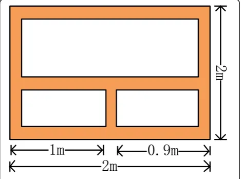
scene geometry is depicted in Fig.7. The thickness of the
wall is 0.20 m and relative permittivity of 6.4. The width of the front wall and the side walls are 2.45 m and 2.40 m, respectively. This radar test system is placed 1.00 m from the corner of the building. Four sets of experimental data
are tested in the experiment with a sample shown in Fig.7.
The tilt angular of the array baseline is 45°. The radar
Fig. 2The image from direct path
Fig. 3The image from double reflection path
antenna installed on the car forms a 1.80 m long synthetic aperture, and the interval between adjacent antennas is 0.10 m. The stepped frequency continuous waveform is
employed [15], with the frequency starting from 1 GHz to
2 GHz with the frequency interval 10 MHz.
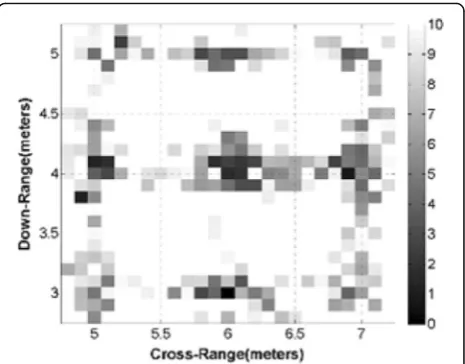
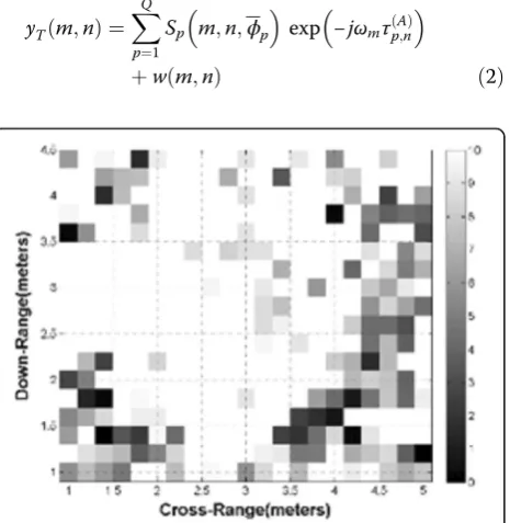
The multi-viewpoint imaging results of direct path imaging dictionary and double reflection imaging
dic-tionary are shown in Figs.8and9, respectively. The final
fusion result is shown in Fig. 10. It is clear that the
noises have been deleted completely and the location and strength of the corner can be detected correctly. As
shown in Fig.11with the algorithms of [7], although the
corners of interest are visible in the image, it is difficult to discriminate them from other scatterers and clutter.
As can be seen from Table2, the ENT values of [7] are
larger, the clutter of images is more, and the images are relatively chaotic. At the same time, the TCR and SCR values of the proposed algorithm are larger, and the qual-ity of imaging results is better.
3 Conclusions
This paper considers the problem of multipath ghosts elimination for the through-wall radar imaging. In the experiment of building feature extraction, while the obser-vation distance between radar and building is relatively closer, the corner of a building is regarded as a complex scatter. So if the corner is regarded as a simple point target to be extracted, the image will appear defocus and more false images. In order to solve this problem, the double reflection imaging dictionary is proposed to extract
the scattering center of the building by building a direct wave dictionary and the second reflection dictionary. Multi-perspective image fusion method is used to accur-ately identify the corner position of the building area, enhance the scattering amplitude of the corner, suppress a lot of wall clutter and background noise. The processing results of GprMax simulation data and experimental data show that the whole image is relatively clear.
4 Methods
4.1 TWRI signal model
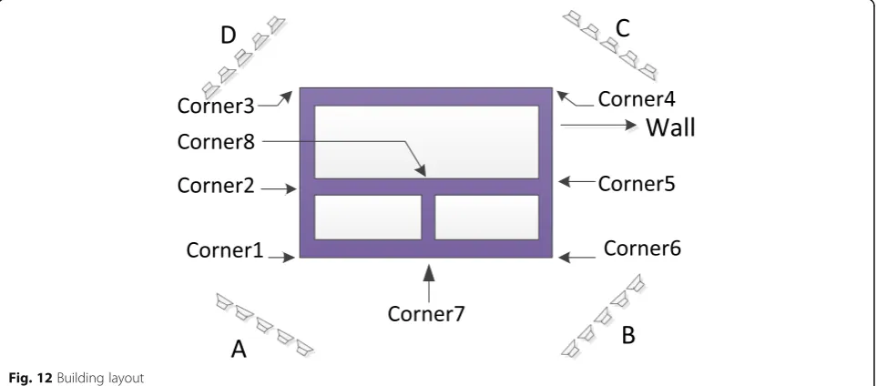
As shown in Fig.12, the building model is a simple
lay-out of three rooms with the walls of 0.1 m thickness. We consider a monostatic synthetic aperture radar im-aging system. The data acquisition is carried out in an oblique position, which significantly attenuates the wall returns and enhances corner scatterers. Let the antenna
at the nth location illuminates the scene with a
stepped-frequency signal of M frequencies, and the mth
fre-quencyωmis defined as
Fig. 5The image result of [7]
Table 1Comparison of effect of simulation experiment
Algorithm TCR/dB ENT SCR/dB
The algorithm in [7] 1.6843 0.6518 −10.0881 The proposed algorithm 2.4852 0.1157 −0.2118
Fig. 6Photograph of the experimental scene
ωm¼ω0þmΔω;m¼0;⋯;M−1 ð1Þ
where ω0 and Δω denote the lowest frequency in the
bandwidth spanned by the stepped-frequency signal and the frequency step size, respectively.
4.2 The direct propagation path signal model
According to the theory of physical optics, the response of the scene can be modeled as the sum of responses from individual corner scatterers, assuming that the scatterers do not interact with each other. Thus, the
dir-ect path echo received by thenth transceiver at themth
frequency can be represented as [6,7]
yTðm;nÞ ¼
XQ
p¼1
Sp m;n;ϕp
exp −jωmτð ÞpA;n
þw mð ;nÞ ð2Þ
where Q is the number of corner scatterers present in the illuminated scene, τðpA;nÞ is the direct path two-way
traveling time of the signal from thenth antenna to the
pth corner scatterer. The termw(m,n) in Eq. (2) models the contributions of other wall scatterers, noise, and the multipath propagation effects. The canonical scattering responseSpðm;n;ϕpÞof thepth corner reflector is given
by [7]
Sp m;n;ϕp
¼Ap sinc ωmLp
c sin ϕp;n−ϕp
ð3Þ
where the variables Ap, Lp, and ϕp, respectively, define
the amplitude, length, and orientation angle of the pth corner, and the variable ϕp, n denotes the aspect angle
associated with the pth corner reflector and the nth antenna.c= 3 × 10⁸m/s.
Fig. 8The image from direct path
Fig. 9The image from double reflection path
Fig. 10The fusion result
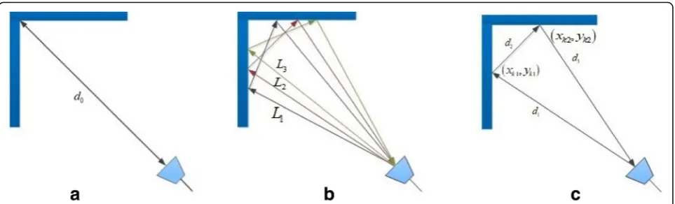
When the antenna array obliquely illuminates the wall,
the echo transmission path is shown in Fig.13a, and the
direct path traveling time of the signal from the nth
antenna to the pth corner scatterer can be represented
as
dand εare the thickness and relative permittivity of the wall, respectively θ is the tilting angle of the antenna array.
In the case of complex imaging scenes, the defocus and virtual images will appear in the imaging results if the corner of the building is regarded as a simple point target; therefore, the double reflection echo model of the corner is introduced in this paper.
4.3 The double reflection propagation paths signal model The indoor walls cause that electromagnetic waves not only travel between corners and antennas, but also re-flect many times between antennas and walls, which
make the received signals appear multi path echo [10].
For simplicity, the corner scattering center is regarded
as the dihedral and the double reflection characteristics of the corner are the major issues that will be discussed
in this paper, as shown in Fig.13b. The double reflection
echo is similar to the first-order multipath effect in the
building. We assume that there are totally Kdouble
re-flection propagation paths in the effective rangedfiniteof
the corner, which are expressed as path L1, L2, ⋯, LK,
respectively [11]. Let yJkðm;nÞ represents the double
re-flection echoes received by the path Lk at the mth
fre-quency of the nth transceiver. Thus, the double
reflection echoes received by the nth transceiver at the
mth frequency can be written as
yJðm;nÞ ¼X
tion with the pth corner. If the corner of the effective range is dfinite, and the distances between the double
reflection point and the pth corner meet jxp−xk1j
<dfinite, jxp−xk2j<dfinite, jyp−yk1j<dfinite, and jyp−yk2j
<dfinite four conditions in Eq. (7),ℑ[xp,yp] = 1. The
ex-pression of the indicator function is given by
ℑ xp;yp
Other double reflections that do not satisfy this
condi-tion in Eq. (7) are not considered. The τðpk;nÞ in Eq. (6)
Table 2Comparison of the effect of measured algorithm
Algorithm TCR/dB ENT SCR/dB
The algorithm in [7] 1.0288 0.4774 −8.2636 The proposed algorithm 2.1964 0.2221 −4.9635
describes the kth double reflection path traveling time
from the nth antenna to the pth corner scatterer. The
electromagnetic wave propagates along this path d1→
d2→d3shows in Fig.13c, or vice versa. Theτðpk;nÞ is given
of the two reflection points of thekth double reflection, respectively.
Based on the above analysis, the total received signal of building corner echoes is a combination of direct path echo and the double reflection echoes returns, which is described as
y mð ;nÞ ¼yTðm;nÞ þyJðm;nÞ: ð9Þ
4.4 Sparse representation of the image
In view of the corner model in the indoor environment, the direct path imaging dictionary and the double reflec-tion imaging dicreflec-tionary are constructed based on the
sparse description [10, 11], and the virtual images are
suppressed based on the non-correlation of noise in dif-ferent dictionaries.
The building scene is divided into NX×NYpixels. The
imaging dictionary AT corresponds to the direct
trans-mission between the location of the antenna and the pixels in the corner of the building, which is called the
direct path echo dictionary. The imaging dictionary AJ
corresponds to multiple double reflection transmission between the location of the antenna and the pixels in
the corner of the building, which is called the double
re-flection echo dictionary. The AT denotes the MN×
NXNYdimensional matrix and is expressed as
AT ¼ quency and the (i,j)th pixel point with the scattering amplitude AAi;j and the corresponding direct propaga-tion path time delayτði;AjÞin Eq. (12).
The kth double reflection echo dictionary AJk is an
MN×NXNY dimensional matrix with the expression
given by ple of the mth frequency between the nth transceiver from the (i,j)th pixel point in Eq. (14).τði;kjÞ is the corre-sponding double reflection propagation path delay with the same form as Eq. (8), andAkrepresents the
scatter-ing amplitude of the double reflection propagation path of the (i,j)th pixel point.
SJk;i;jðm;nÞ ¼Ak exp −jωmτ
nates of the two reflection points of the kth double re-flection correspond to the (xk,yk), respectively. By
stacking all the received signal y(m,n) in one column vector, we obtain the radar observation vector with the following expression
y¼½yð1;1Þ;yð1;2Þ;⋯;y Mð ;NÞT: ð16Þ
The real imaging scenario can be estimated based on
the received signalywhich can be written as
y¼ATxTþ
XK
k¼1
AJkxk: ð17Þ
where xT and xk are defined as the scattering coefficient
vector. The multiple scene estimation images can be obtained according to multiple dictionaries. Assuming that
NXNYis much larger thanMN, we can conclude thatAT
andAJk are only row full rank matrices. The dictionary of direct wave imaging is represented byADPD, whereADPD=
AT and AþDPD represents the pseudo-inverse of ADPD.
Multiply both sides of Eq. (17) byAþDPD, we can derive
certain pixel value, the other terms are very small. Since the corner of the building is regarded as an extended tar-get, not a scatter point tartar-get, AþDPDAJ1x1represents the
corresponding multipath ghost image to pathL1. Similarly,
Aþ
DPDAJ2x2and A
þ
DPDAJ3x3 are respectively the multipath
ghost images related to pathL2and pathL3. AssumingΦy
is the measurement matrix, the scene imaging results of the direct path imaging dictionary can be obtained by solving sparse signal recovery problem in Eq. (19) [12].
xT¼ arg min
x k kxT 0 s:t ^y−ΦyADPDxT
2
2≤ε0
ð19Þ
LetAðMPDkÞ be thekth double reflection imaging
diction-ary, where AðMPDkÞ ¼AJk , and A
ðkÞþ
MPD represents the
pseudo-inverse. Multiply both sides of Eq. (17) by AþDPD,
we can derive
where AðMPDkÞþAJkxk represents the corresponding multi-path image to double reflection multi-path Lk. The scene
imaging results of the kth double reflection imaging dictionary can be obtained by solving sparse signal re-covery problem in Eq. (21).
OMP algorithm is used to solve the problem of sparse
signal recovery of Eqs. (19) and (21).
4.5 Image fusion of multiple dictionaries
Based on the above analysis, both the estimated image derived from the direct path imaging dictionary and the estimated images produced by the double reflection im-aging dictionaries contain the target image of interest. Moreover, the elements will form a highlight focused re-gion located at the position of the true target, and the
noise in these images will not overlap [15].
In order to extract the building corner and delete the noise, we fuse these estimated images together. Based on the above features, these images are fused by a non-coherent image fusion method to produce a no-false
image. To be clear, for the image xTand x1 of this
ex-ample, only the pathL1is considered, we derive
xf;1¼j j xT j j ¼x1 ADPDþ ATxTþAþDPDAJ1x1 Að ÞþMPD1 ATxTþAð ÞþMPD1 AJ1x1
|·| represents the absolute value operation. By inspecting Eq. (22), we could observe thatAþDPDATxT andAðMPD1ÞþAJ1 x1are the target images derived from the direct path im-aging dictionary and the first double reflection imim-aging dictionary, respectively. AþDPDAJ1x1 and A
ð1Þþ
MPDATxT are
the fake images and noise with respect to the direct path imaging dictionary and the first double reflection im-aging dictionary, respectively. It is clear that the third item jAþDPDATxTj jAMPDð1ÞþAJ1x1j represents the genuine
target image, and the other three items are approxi-mated to zeros. In the same way, we obtain xf, k which
denotes the fusion result of image xT and xk from the
Three double reflections are taken into account, and the
expression of the fused imagexfis described as below
xf ¼xf1xf2xf3 ≈ AþDPDATxT 3
the building, it is necessary to incoherent fusion of im-ages from multiple-viewpoint, we have
xf‐sum¼xf‐Aþxf‐Bþxf‐Cþxf‐D ð24Þ
wherexf‐sumdenotes the fusion result of imagexf‐A,xf‐ B, xf‐C, and xf‐D, which are respectively the image
de-rived from the four single-location image, as shown in Fig.12.
Abbreviations
ENT:Entropy of the image; OMP: Orthogonal matching pursuit; SCR: Signal-to-clutter ratio; TCR: Target-Signal-to-clutter ratio; TWRI: Through-the-wall radar imaging
Acknowledgements
The authors would like to thank Tingfa Xu for the support.
Authors’contributions
HD and TX conceived of the building feature extraction method based on double reflection imaging dictionary. All authors read and approved the final manuscript.
Funding
This work was supported by the Major Science Instrument Program of the National Natural Science Foundation of China under grant 61527802. This work was supported by the Major Science and Technology Foundation of Guangxi Province under grant AA17204093.
Availability of data and materials All data are fully available without restriction.
Competing interests
The authors declare that they have no competing interests.
Author details
1Key Laboratory of Photoelectronic Imaging Technology and System, Beijing
Institute of Technology, Beijing, China.2School of Information and Communication, Guilin University of Electronic Technology (GUET), Guilin, China.
Received: 6 May 2019 Accepted: 25 July 2019
References
1. A. Bouzerdoum, V.H. Tang, S.L. Phung, inIEEE Radar Conference (RadarConf). A low-rank and jointly-sparse approach for multi polarization through-wall radar imaging (Seattle, 2017), pp. 0263–0268
2. J. Liu, L.j. Kong, X. Yang, Refraction angle approximation algorithm for wall compensation in TWRI. IEEE Geosci. Remote Sens. Lett.13(7), 943–946 (2016) 3. B. Yektakhah, K. Sarabandi, All-directions through-the wall radar imaging
using a small number of moving transceivers. IEEE Trans. Geosci. Remote Sens.54(11), 6415–6428 (2016)
4. P.C. Chang,Near Zone Radar Imaging and Feature Capture of Building Interiors(The Ohio State University, Columbus, 2008)
5. Y. Jia, X. Zhong, J. Liu, Y. Guo, Single-side two-location spotlight imaging for building based on MIMO through-wall-radar. Sensors16(9), 1441 (2016)
6. E. Lagunas, M.G. Amin, F. Ahmad, M. Najar, Determining building interior structures using compressive sensing. J. Electron. Imaging22(2), 381–388 (2013) [55] 7. E. Lagunas, M.G. Amin, F. Ahmad, M. Najar, Pattern matching for building
feature extraction [J]. IEEE Geosci. Remote Sens. Lett.11(12), 2193–2197 (2014) 8. B. Chen, T. Jin, B. Lu, Z. Zhou, inIET International Radar Conference.
Polarimetric characteristics analysis of interior structures of a building in through-the-wall radar imaging (2013), p. 0229
9. H. Liu, B. Jiu, F. Li, Y. Wang, Attributed scattering center extraction algorithm based on sparse representation with dictionary refinement. IEEE Trans. Antennas Propag.65(5), 2604–2614 (2017)
10. M. Leigsnering, F. Ahmad, M. Amin, A. Zoubir, Parametric dictionary learning for sparsity-based TWRI in multipath environments. IEEE Trans. Aerosp. Electron. Syst.52(2), 532–547 (2016)
11. P.C. Chang, R.J. Burkholder, J.L. Volakis, High-frequency EM characterization of through-wall building imaging. IEEE Trans. Geosci. Remote Sens.47(5), 1375–1387 (2009)
12. A. Hoorfar, W. Zhang, inApplied Computational Electromagnetics. MIMO radar imaging of targets behind multilayered walls using compressive sensing (2015), pp. 1–2
13. S. Guo, G. Cui, M. Wang, L. Kong, X. Yang, Similarity-based multipath suppression algorithm for through-wall imaging radar. IET Radar Sonar Navig.11(7), 1041–1050 (2017)
14. X. Chen, W. Chen, Double-layer fuzzy fusion for multiview through-wall radar images. IEEE Geosci. Remote Sens. Lett.12(10), 2075–2079 (2015) 15. G. Cui, L. Kong, X. Yang, Reconstruction filter design for stepped-frequency
continuous wave. IEEE Trans. Signal Process.60(8), 4421–4426 (2012)
Publisher’s Note