R E S E A R C H
Open Access
Reconfigurable cognitive transceiver for
opportunistic networks
Marco Maso
1*, Ejder Ba¸stu ˘g
2, Leonardo S Cardoso
3, Mérouane Debbah
2and Özgür Özdemir
4,5Abstract
In this work, we provide the implementation and analysis of a cognitive transceiver for opportunistic networks. We focus on a previously introduced dynamic spectrum access (DSA) - cognitive radio (CR) solution for primary-secondary coexistence in opportunistic orthogonal frequency division multiplexing (OFDM) networks, called cognitive
interference alignment (CIA). The implementation is based on software-defined radio (SDR) and uses GNU Radio and the universal software radio peripheral (USRP) as the implementation toolkit. The proposed flexible transceiver architecture allows efficient on-the-fly reconfigurations of the physical layer into OFDM, CIA or a combination of both. Remarkably, its responsiveness is such that the uplink and downlink channel reciprocity from the medium
perspective, inherent to time division duplex (TDD) communications, can be effectively verified and exploited. We show that CIA provides approximately 10 dB of interference isolation towards the OFDM receiver with respect to a fully random precoder. This result is obtained under suboptimal conditions, which indicates that further gains are possible with a better optimization of the system. Our findings point towards the usefulness of a practical CIA implementation, as it yields a non-negligible performance for the secondary system, while providing interference shielding to the primary receiver.
Keywords: Cognitive radio; Transceiver implementation; OFDM; CIA; Interference cancelation
1 Introduction
A popular research topic in wireless communications is the design of efficient coexistence techniques, allowing different systems to share the same bandwidth. A num-ber of candidate coexistence techniques aim to combat the ever-growing spectrum scarcity issue experienced by modern data-centric networks. A prominent approach, called dynamic spectrum access (DSA) [1], aims to cir-cumvent the rigid legacy spectrum policies by letting unlicensed devices access the spectrum opportunistically. Cognitive radios (CRs) [2] provide an interesting means to implement DSA. In the CR paradigm, two different types of devices compose a network. They are known as primary system devices (the holder of the license to use a frequency band) and secondary system devices (cogni-tive, opportunistic non-licensed users). Secondary system devices access the spectrum licensed to the primary ones
*Correspondence: [email protected]
1Singapore University of Technology and Design, 20 Dover Drive 138682, Singapore
Full list of author information is available at the end of the article
dynamically, by means of several techniques that mitigate the interference experienced by the primary system.
In a previous contribution [3], we considered the single-antenna primary-secondary coexistence problem for orthogonal frequency division multiplexing (OFDM)-based two-tiered networks using time division duplex (TDD). Therein, we proposed cognitive interference alignment (CIA) [3], an optimal strategy to realize the aforementioned coexistence, maximizing the spec-tral efficiency at the secondary system. In [4], we described the implementation of CIA’s parent tech-nique, Vandermonde-subspace frequency division mul-tiplexing (VFDM) [5], by means of the SDR4All [6] toolkit. This implementation was limited to the sec-ondary link, since SDR4All lacks real time processing capabilities, which hindered our capacity to perform timely channel state information (CSI) estimations and forced us to perform offline base-band processing. In fact, implementing any adaptable precoder scheme is a daunting task since it requires timely channel estima-tions of the direct link and, in general, a good level
of synchronization. For CIA, the problem is not differ-ent, as the absence of interference is ensured only if perfect synchronization of both primary and secondary signals is achieved at the primary receiver [7]. State-of-the-art contributions in the literature on software-defined radio (SDR) implementations of interference alignment testbeds address these issues by introducing backbones (TCP/IP links) connecting multiple-antenna SDR devices [8,9], to provide CSI sharing and synchronization. Alter-natively, solutions based on offline signal processing [9,10] focus on more theoretical aspects, simplifying the synchronization issues and the impact of hardware impairments.
In this contribution, we first present the design of a reconfigurable transceiver architecture, based on a flexi-ble SDR approach. This efficient and responsive platform design is suitable for cognitive radio physical layer solu-tions for opportunistic networks. The architecture of our transceiver is characterized by a modular and transpar-ent software structure composed of highly interoperable software blocks. Accordingly, the latter can be adopted to create flexible and easily configurable transmit/receive chains. As a result, the proposed transceiver is able to quickly switch between transmission schemes (acOFDM, CIA or a mix of both) as required, hence the ‘reconfig-urable’ denomination. As a second step, we make use of this new reconfigurable solution to take one step towards a full implementation of CIA. In particular, we aim at providing a proof-of-concept; thus, we focus on a point-to-point cognitive radio channel as in [3]. We note that, differently from the aforementioned state-of-the-art con-tributions, herein, the necessary perfect synchronization of both primary and secondary signals at the primary receiver is achieved by means of a simplified strategy, based on a hybrid transceiver design. In practice, both pri-mary and secondary transmitter chains are implemented in the same hardware, transforming the 2 × 2 model studied in [3] into a hybrid 1×2 one. Furthermore, the CSI required by the devices to perform their operations, i.e., precoding at the transmitter and decoding at the receivers, is not obtained through CSI sharing between the devices, as typically done in the literature. Instead, it is acquired independently by each interested device by means of channel estimations.
We show that the proposed transceiver is fast enough to exploit the channel reciprocity within the channel coher-ence time, from the medium perspective, i.e., from the transmitter’s antenna (after the radio frequency front-end) to the receiver’s antenna (before the radio fre-quency front-end). Remarkably, this can be achieved regardless of the TDD uplink-downlink radio frequency (RF) calibration, due to the special nature of the CIA precoder. This crucial aspect is usually downplayed in similar contributions [8-10], where the legitimacy of
the assumption of perfect channel reciprocity is not assessed, but is indeed fundamental for the correct implementation of any adaptive precoding scheme in a TDD scenario. Subsequently, a performance study of the primary and secondary links under an interference cancelation constraint at the secondary system is pro-vided. Extensive field tests are performed to validate the proposed reconfigurable transceiver design, provid-ing encouragprovid-ing results. We show that CIA achieves a non-negligible throughput while guaranteeing the per-formance of the OFDM transmission. In other words, the effective interference mitigation realized at the sec-ondary system allows a profitable coexistence of the two systems.
This paper is organized as follows: The scenario and signal model are described in Section 2; the baseband design of the transceiver is presented in Section 4; a discussion on the validity of the channel reciprocity assumption for CSI acquisition purposes at the trans-mitter is carried out in Section 3; the transceiver chains description is given in Section 5; the experimental results of the field tests are provided in Section 6; we finally conclude and discuss future research directions in Section 7.
2 Cognitive interference alignment
Before starting, a brief review of CIA is in order. We start by introducing the mathematical notation adopted throughout this contribution. The result of the integer division of m, n ∈ N is denoted as mn. Lower case italic symbols (e.g.,b) represent scalar values, a lower case bold symbol (e.g., b) a vector and an upper case bold symbol (e.g., B) a matrix. [B]m,n is the element of the
matrix Bat the mth row and the nth column, whereas
bm is the mth element of the vector b. All vectors are
columns, unless otherwise stated.INis the identity matrix of size N × N, 1N is the N-sized all ones vector and 0N×M is the all zeros matrix of size N × M (with 0N being the N-sized all zeros vectors). The diag(·) opera-tor transforms a vecopera-torbinto a diagonal matrixB, such that [B]i,i=bi. Thevecoperator is denoted by vec(·), and
applied to the matrixB= [b1,. . .,bN] it yields vec(B) =
bT1,. . .,bTN T
. The transpose and transpose conjugate operators are denoted by the superscripts T and H (e.g., BT,BH), respectively. Finally, givenc ∈ C, we denote by
c∗ and c the complex conjugate and phase angle of c, respectively.
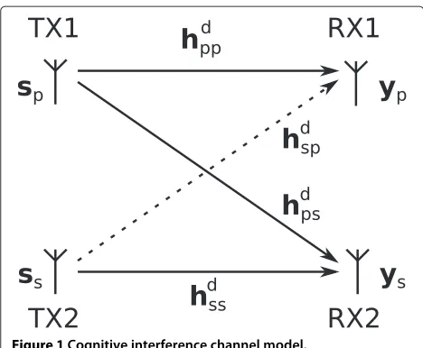
Figure 1Cognitive interference channel model.
transmitter/receiver pair denoted by TX2/RX2. TDD is assumed throughout the model. TX1 performs an OFDM transmission towards RX1, similar to what is proposed in recent standards, such as long term evolution (LTE) [11], withNsubcarriers and cyclic prefix (CP) size ofL, for a total block length ofN+L. TX2 is CIA-based (also of size
N+L), and nulls its interference towards RX1 as described in [3].
Let us define sp ∈ CN, ss ∈ CL as the input sym-bol vectors at TX1 and TX2, respectively. Additionally, we defineF ∈ CN×N as a unitary discrete Fourier trans-form (DFT) matrix with [F](k+1,l+1) = √1Ne−i2π at TX1 and TX2, respectively, as
xp=AF−1sp (2) vectors of size l + 1 taps, representing the downlink between the transmitter in system ‘a’ and the receiver in system ‘b’. The uplink between the receiver in system a and the transmitter in system b is defined accord-ingly as huab. The convolution of each coded symbol vectorxi with the related channel hdab can be modeled
as an extended Toeplitz matrix Hdab ∈ C(N+L)×(N+L),
If we assume perfect synchronization at the receiver, the received signalsyp ∈ CN at RX1 andys ∈ CN+Lat RX2 can be written as
yp=FB that, in (5) and (6),npandnsare additive white Gaussian noise (AWGN) vectors, modeling the thermal noise at the receivers with powerσ2.
At this stage, we can characterize the precoderE, by analyzing the interference constraint that TX2 must sat-isfy. As in [3], we require that no interference signal component be perceived at RX1, after the CP removal operation and DFT, framing our scenario in theoverlay
cognitive paradigm. Now, letH˜dsp = FBHdsp. In order to protect RX1 from undesired interference, the following must hold
˜
Hdspxs= ˜HdspEss=0N. (7)
We know that rank
˜ Hdsp
= N, regardless of the chan-nel realization. Thus, by the rank-nullity theorem [12], we have dim kerH˜dsp
= L. Then, ifEis defined as the precoder whose columns span kerH˜dsp
, (7) is always sat-isfied, regardless of the realization ofss. We know from [3] that the optimal precoder to maximize the spectral efficiency of the secondary link issemi-unitary.
3 TDD and channel-state information
In principle, the uplink and downlink channel in a TDD system are reciprocal [13]. However, reciprocity holds only when seen strictly from the medium perspective, i.e., from the TX antenna to the RX antenna. In real imple-mentations of TDD systems, overall channel reciprocity is in general an unrealistic assumption since uncalibrated RF imposes distinct disturbances of both the TX and RX chains of the same radio device [14,15]. A generally accepted assumption is that the RF part provides a flat transfer function inside the bandwidth of the signal. Then we can model the relationship between the downlink and uplink channels as
hdsp= 1
χhups, (8)
with χ ∈ C. Note that, in general, χ depends on all disturbances present in the TX and RX chains of the con-sidered pair of transceivers [14], and its variations occur at a period much larger than the coherence time of the con-sidered channels. Remarkably, in our case, such a scalar disturbance has no influence on the interference cance-lation capabilities of the null-space precoder E. In fact, the null-space is closed under scalar multiplication [16], hence we have that
ker
˜ Hdsp
=ker
χH˜dsp
=ker
˜ Hups
. (9)
This implies that the channel reciprocity from the medium perspective can be exploited. As a consequence, the uplink channel estimation can be used to design the precoder adopted in the downlink transmission. This will allow for a much simpler channel estimation procedure, as detailed in the following.
4 Baseband design
Mitola introduced SDRs [17] on the basis that, as time goes by, processing power becomes cheap enough to allow offloading baseband signal processing to general-purpose processors (GPPs). In such an approach, baseband pro-cessing is provided by a suitable software toolkit, whereas the RF processing is performed by a dedicated hardware. Thus, test algorithms can be implemented on GPP, reduc-ing the implementation time and allowreduc-ing tests with real transmissions using actual hardware transceivers. From that seminal paper in 1995, until today, SDRs have evolved a long way, going from a military conceptual technology [18] to actual commercially available products [19].
The transceiver design presented in this work is based on the concept of SDRs. The design was developed for and tested on the universal software radio peripheral (USRP) 1 radio hardwarea [19]. These radios are composed of two parts: a motherboard and one or two daughterboards. The motherboard controls the RF, universal serial bus (USB) circuitry and sampling. The adopted daughter-board is the RFX 2400, operating at 2.4 GHz industrial,
scientific and medical (ISM) band. In this regard, we note that the default hardware configuration of all these devices/blocks is adopted for all our implementations and experiments (see [19] for specifications). Therefore, no hardware modification is performed or proposed in this work to implement the reconfigurable transceiver. In fact, all the customizations and modifications are performed at software level. In particular, no additional filtering oper-ation is performed before or during the baseband signal processing.
The software toolkit adopted to perform the baseband signal processing is the so-called GNU Radio library [20]. This popular library offers a flexible way to create base-band designs, by connecting ready-made signal processing basic blocks using python or by creating such blocks in C and C++. Afterwards, a flow graph made of these blocks can be visually prepared and executed by means of the graphical tools provided with the library. In practice, first, the developer implements signal processing blocks and transceiver chains as a toolbox of GNU Radio. Then, after the compilation and installation of this toolbox, corre-sponding flow graphs of the transceiver chains are created by properly connecting these modular blocks. The signal processing blocks and the transceiver chains described in Section 5 have been implemented following this approach. A simplified approach to the baseband design is adopted in this work, to guarantee perfect synchronization of CIA and OFDM signals at RX1 and satisfy a fundamental condition to ensure the effectiveness of CIA [3]. This is achieved by implementing both TX1 and TX2 chains on the same baseband transceiver, transforming the two TX-two RX model into a hybrid one TX-TX-two RX. However, in spite of this simplification, many other development issues need to be addressed and specific implementation solutions must be found, as described in the remainder of this section, then in Section 5 and Section 6. As CIA stands on some critical assumptions, for example, chan-nel reciprocity in TDD mode, intermediate checks need to be performed to validate our development and better understand the limitations.
Table 1 Operating mode of the devices for uplink and downlink phases.
Device Uplink Downlink
HT OFDM RX OFDM TX
OT OFDM TX OFDM RX
CT CIA RX CIA RX
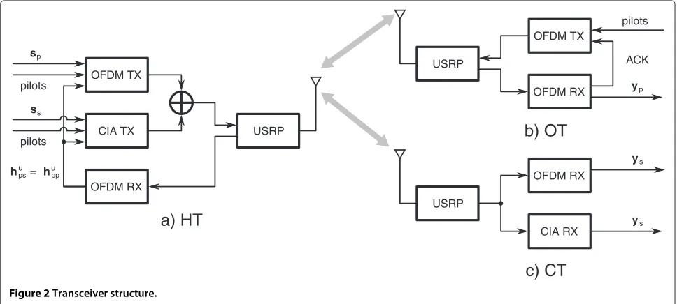
re-configuration, any device can potentially act as an OFDM/CIA transceiver. Figure 2 provides the structure of the three devices, showing the configuration of the chains according to the states described in Table 1. We recall that all communications are in TDD; thus, the transmitters and receivers access the channel in an alternating manner. The communications between the devices are performed according to the following.
4.1 Channel estimation and triggering
As a first step, OT sends a trigger frame to HT. This trigger signals the start of a communication session. Pilot symbols are included in this frame to allow for channel estima-tion at the HT. This is necessary to decode the trigger and, in the future (next version of the implementation), to perform optimal power allocation. With the hybrid structure, such knowledge ofhups is always accessible by both the OFDM and CIA transceiver chains, as shown in Figure 2. We remind the reader that, as seen in Section 3, thehups CSI is sufficient to construct the null-space pre-coderE. For the moment, this CSI is stored in the CIA transmitter chain for the subsequent precoder generation during the downlink phase. We note that no trigger mes-sage is sent by CT during the uplink phase. Unlike [3], no optimal power allocation is performed for the downlink
CIA transmission, reducing the computational burden for HT.
4.2 Downlink transmission
Once triggered, the downlink phase starts. Two indepen-dent frames are generated in parallel, one for OFDM and one for CIA. For simplicity, the input symbol size is set such that the two frames have the same size. Then, the two frames are summed up and sent to the USRP for transmission. We recall that TX2 was introduced as an opportunistic device that can obtain the necessary CSI to designE, in Section 2. Herein, the cognitive nature is rep-resented by HT’s ability to act both as an OFDM receiver during the channel estimation phase and as a CIA trans-mitter in the downlink phase, under the adopted hybrid approach. We remark that, this scheme yields a simplified synchronization of the OFDM and CIA signals at the OT, but does not provide advantages in terms of channel esti-mation. In fact, any stand-alone CIA cognitive transceiver (without OFDM transmitter capabilities) would compute the null-space ofHdspas does HT.
4.3 Downlink reception
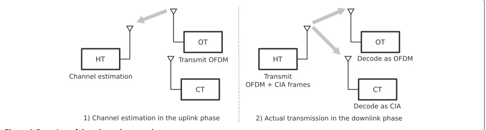
During the downlink phase, both OT and CT receive and decode their respective signals. The received symbols (after equalization) are stored for further analysis. Then, an ACK frame is constructed (including pilot symbols) and transmitted from OT back to HT, to confirm the pos-itive reception and trigger a new transmission. We note that no uplink transmission by CT is required. For sim-plicity, no channel coding scheme is considered in this work. The analysis of channel coding on the performance of the reconfigurable transceiver is the subject of future research. For the sake of clarity, a brief explanation of
OFDM TX
CIA TX
OFDM RX
USRP pilots
OFDM TX
CIA RX USRP
yp
USRP
OFDM RX
pilots
ACK
a) HT
b) OT
c) CT
OFDM RXys
ys
sp
ss
pilots
hpsu = hupp
these steps, from channel estimation to downlink recep-tion, is given in Figure 3. Throughout the paper, these steps are assumed unless otherwise stated.
5 Transceiver chains description
Before starting, we note that the OFDM implementa-tion herein described has been created for the purpose of this proof-of-concept to increase the flexibility and trans-parency of the legacy GNU Radio implementation. It is composed of blocks, fully written in C++, that can be eas-ily plugged to (or unplugged from) other blocks within the graphical tool of GNU Radio, according to one’s needs. This allows both a more efficient block reuse and the creation of chains that can work with custom frame struc-tures. Naturally, the same modular structure has been adopted to create the CIA implementation, for which sev-eral blocks of the OFDM implementation are efficiently re-used, as discussed in the following. Finally, in order to achieve the desired reconfigurability of the transceiver, a set of novel controller blocks has been created to pro-vide full support to the aforementioned modular structure and coordinate the multiple chains coexisting within the transceiver.
As previously stated, the cognitive transceiver pro-posed in this work has four possible operating modes, namely OFDM transmitter/receiver and CIA transmit-ter/receiver. In the following, the block structure of each mode is described.
5.1 OFDM transmitter
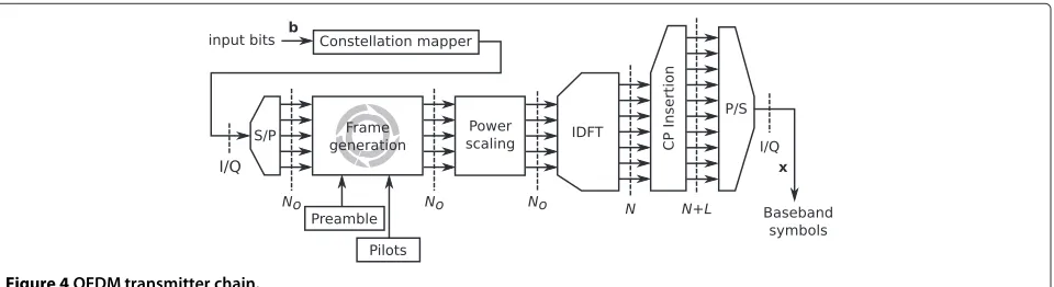
Consider the block representation given in Figure 4, a detailed description is provided in the following.
5.1.1 Constellation mapper
This block accepts a bit sequence as input and yields its digitally modulated version as output. We define A as the modulated symbol alphabet of order M. Now, let b ∈ [0, 1]K be the K-sized row input bit vector fed to the block, such thatK = logK
2M ∈ N. Consequently, we
defined ∈ AK as the data row vector at the output of
the constellation mapper, representing the digitally modu-lated version ofb. We note thatbcan be either a binary file or a pseudo-random binary sequence, with the addition of an appropriate padding to satisfy the above size condition. Any mapping function can be implemented in this block to support the chosen digital modulation scheme.
5.1.2 Serial to parallel
This block prepares the modulated symbols for the frame generation in the frequency domain. Let us assume that only a central portion of the available spectrum may be used to obtain a smoother impulse response of the trans-mit/receive filters in the USRPs. In particular, we letNobe the number of active subcarriers, i.e.,occupied tones, out of theN available for the OFDM transmission. Accord-ingly, a check on the size of d is performed before the serial to parallel operation. IfNK
o ∈/N, then a padding vec-tor of dummy symbolsdp ∈ CNo
1+K
No
−K
is appended tod, such thatd =
d dp
, new padded data row
vec-tor of sizeK˜ = No
1+ NK o
, is obtained. Naturally, if
K
No ∈N, thend=dandK˜ =K. This block transforms the data vectordin a data matrixD(O) ∈ ANo×NoK˜ , mapping themth element ofdtoD(O)
m−NoNom,Nom+1
. Finally,
we note that K, NO andN are user-defined parameters
known at both ends of the communication. These param-eters are kept constant throughout all the duration of the tests. This comes without loss of generality and the con-sistency of the outcome of our tests persists over different system configurations.
5.1.3 Frame generation
The frame generation block accepts a data matrixD(O)as input and constructs an OFDM frameS, defined as
S=
G P(O) D(O)
, (10)
where G ∈ CNo×Rg is a preamble matrix with pseudo-random entries andP(O) ∈ CNo×R(pO) is a deterministic
Figure 4OFDM transmitter chain.
pilotmatrix, knowna prioriby the frame generator. Note that,Rg,R(pO)∈N.
We start by describing the preamble matrixG, adopted for time and frequency synchronization purposes at the receiver. We consider a preamble structure according to the classical procedure proposed by Schmidl and Cox (S-C) [21]. This approach makes use of the statistical proper-ties of specially constructed sequences, characterized by interesting auto-correlation properties. In our implemen-tation, we setRg = 1 andGdegenerates into aNo-sized vectorg, obtained by alternating pseudo-random binary phase-shift keying (BPSK) symbolsgi,∀i ∈
1,No 2
, and
zeros such thatg =
g1, 0,g2, 0,. . .,gNo
2
T
. The adopted pseudo-random sequence should be known at both ends of the communication, to allow for a more precise time synchronization at the receiver (detailed in the follow-ing). In this implementation, we achieve this situation by imposing the adoption of an identical user-defined algo-rithm and initial seed at both the OFDM transmitter and receiver. At this stage, we note that an inverse discrete Fourier transform (IDFT) over theN available subcarri-ers will be performed in the following block, to generate the OFDM symbols. Due to the properties of the IDFT, the time domain representation of g will consist of a repeated sequence over one full OFDM symbol, as in the S-C algorithm.
In principle, the knowledge of the preamble at the receiver could enable channel estimations at the latter (for equalization purposes) by evaluating the received instance ofg, as done in classical pilot-based estimations. Never-theless, the significant number of zeros ingmay decrease the quality of said estimation, even if linear interpolation techniques were to be adopted. Therefore, the pilot matrix P(O) of sizeNo ×R(pO) is appended to the frame afterg,
to provide a more reliable tool for channel estimation at the receiver. In particular, we letP(O) = p(O)1T
R(pO) , with
p(O)∈CNo deterministic vector known both at the trans-mitter and receiver. We remark that a biggerR(pO) could
yield more accurate channel estimations at the receiver but reduces the spectral efficiency of the transmission. Thus, a careful adjustment of this parameter depending on the environment, e.g., perceived signal-to-noise ratio (SNR) at the receiver and coherence time of the channel, could become necessary during the field tests.
5.1.4 Power scaling
At this point, a power scaling may be performed to shape a desired power profile forSbefore the IDFT. Let α(gO),
α(O)
p ,α(dO) ∈ Rbe parameters adopted to scale
indepen-dently the power ofg, P(O) andD(O). We note that, the scaling parametersαg(O),αp(O)andαd(O)are set empirically during the field tests, to achieve a more homogeneous power profile for the signal. The frame obtained at the output of the power scaling block can be written asS =
α(O)
g g α(pO)P(O) αd(O)D(O)
.
5.1.5 IDFT
The matrix S, input to the IDFT block, has size No ×
1+R(pO)+NK˜o
, thus a further padding to S has to be appended to prepare the frame for the N-point IDFT. In fact, the number of occupied tones in the proposed scheme is lower than the number of available subcar-riers, i.e., No < N. Let N = 0(N−No)
2 ×
1+R(pO)+NoK˜
be
a suitable zero padding matrix. The frequency domain representation of the full OFDM frame is defined as
SF =
NT ST NT T
∈CN×
1+R(pO)+NoK˜
. (11)
Then,ST, time domain representation ofSF, is obtained by stacking the N-point IDFT of ST and an additional padding matrix Z = 0N×Rz, included for SNR estima-tion purposes at the OFDM receiver, as further detailed in Section 5.2. Then,ST reads
ST =F−1SF Z∈C(N+L)×
1+R(pO)+NoK˜ +Rz
withF unitary DFT matrix as defined in Section 2 and
Rz ∈ N. Note that, the matrix representation adopted so far has been provided only for the sake of compact-ness. In fact, in the operating framework provided by GNU Radio, algorithms based upon matrix-wise opera-tions are not computationally efficient. Consequently, the
N-point IDFTs (and DFTs) are implemented by means of the computationally efficient algorithms provided by the FFTW [22] C library, based on vector-wise opera-tions. This choice has been made to decrease the overall required computational time.
5.1.6 Cyclic prefix insertion
The CP insertion can be modeled as a matrix operation as
well, that isSCPT = AST ∈ C(N+L)×
1+R(pO)+NoK˜ +Rz
, with ACP insertion matrix as in Section 2. In practice, if we
let ST ∈ CL×
1+R(pO)+NoK˜ +Rz
be the matrix carrying the lastLrows ofST, then the CP insertion operation can be implemented without matrix operations by constructing
SCPT =
STT STT T
.
5.1.7 Parallel to serial
The output of this block is the serialized version of the input stream, ready to be fed to the USRP for transmission. This operation can be written asx(O) = vecSCPT T ∈
C(N+L)
1+R(pO)+NoK˜ +Rz
, withx(O)a row vector.
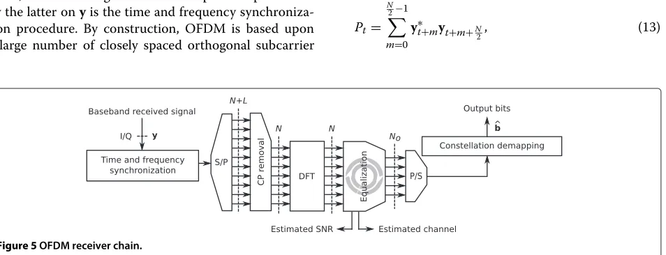
5.2 OFDM receiver
Consider the block representation given in Figure 5. A detailed block-by-block description is provided in the following.
5.2.1 Synchronization
Let us denoteyas the signal obtained after the RF to base-band conversion performed by the USRP. After this oper-ation, y is fed as input to the OFDM receiver baseband chain, as shown in Figure 5. The first operation performed by the latter onyis the time and frequency synchroniza-tion procedure. By construcsynchroniza-tion, OFDM is based upon a large number of closely spaced orthogonal subcarrier
signals, used to bear data on several parallel data streams or channels. In case of missed synchronization of the received frame, such carrier orthogonality is lost. Specif-ically, if the cyclic prefix L is not much larger than the delay spread of the channel, imperfect time synchroniza-tion of the frame may cause inter-block interference (IBI) and decrease the signal to interference plus noise ratio of the useful portion of the signal. Conversely, in case of imperfect frequency synchronization, issues such as inter-carrier interference (ICI) or phase noise may arise [23], breaking the orthogonality between the subcarriers and impairing the decoder. Unfortunately, any communica-tion system may experience a carrier frequency offset due to issues such as Doppler shifts, or imperfections in the phase lock loop responsible for the generation of the car-rier frequency at the transmitter and receiver (used in the RF demodulation step to obtain the baseband represen-tation of the received signal), just to name a few. Thus, an appropriate procedure to achieve time and frequency synchronization is required.
Herein, we exploit the special structure of the pream-ble, described in Section 5.1, and adopt the S-C method [21] to achieve both time and frequency synchronization. First, the timing of the first sample of the preamble is iden-tified. Then, the carrier frequency offset is detected and corrected to achieve frequency synchronization.
In this implementation, the receiver disposes of the same seed adopted at the transmitter to generate the preamble, as explained in Section 5.1, thus is able to
gen-erate a copy ofgT =F−101×N−No
2
gT 01×N−No
2
T , time domain version of the N-sized preamble (CP excluded). Now, let us consider a window ofNreceived samples. We definetas the time index corresponding to the first sam-ple of the window. If we let the window slide along in time that we have, the receiver can search for the preamble by computing Pt, auto-correlation function of the received signal evaluated att,∀t∈N, given by
Pt= N
2−1
m=0
y∗t+myt+m+N
2, (13)
withya = y[a] for clarity in the notation. Let Mtcbe a timing metric, defined as
Mct = |Pt| 2
R2t ∈[0, 1] , (14)
with Rt =
N/2
m=1|yt+m+(N/2)|2 received energy for the second half-window. The properties of the adopted preamble’s auto-correlation induce the formation of a plateau to Mct, whose length is equal to L − l, with l
number of channel taps (excluding the line-of-sight com-ponent) as defined in Section 2. The starting sample of the preamble may be taken to be anywhere within this plateau [21], leading to some uncertainty for the receiver. A two-step timing estimation is adopted to solve this issue. First, acoarsetiming estimation is computed, i.e.,ˆtc, to
iden-tify the approximate position of the preamble within the received sequence by
ˆ
tc=arg max t
Mct. (15)
Then, we select a fixed window of received samples of size N2 +2L, including the sample attˆc(as the(L+1)-th
sample), and compute its cross-correlation withgT as
˜
Pt=
N/2+2L−1
m=0 y∗ˆ
dc−L+mgT,m. (16)
Note that, (16) is feasible ifL≤ N4, condition usually ver-ified in practical systems for matters of spectral efficiency [11]. Now, thefine estimation of the timing of the first sample of the preamble, i.e.,ˆtf, is obtained by exploiting
the property of the peak of the cross-correlationPt˜ as
ˆ
tf = ˆtc+arg maxt ˜
Pt−L−1. (17)
From now on, for clarity, we will lety˜be the received frame after the time synchronization, obtained by discarding the firstˆtf −1 samples ofy. Once the best timing pointˆtf has
been identified, the carrier frequency offset (in subcar-rier spacings)f can be directly estimated by evaluating
ˆ
φ, phase difference between the two halves of the received preamble, in radians, estimated atˆtf as
ˆ
φ = (Pt,ˆt
f). (18)
Accordingly,fcan be computed as
ˆ
f= πφ
N +
2z
N, (19)
withz = 0 for| ˆφ| < π andz ∈ Z\ {0} otherwise. We note that in the set of preliminary experimental OFDM transmissions performed according to the parameters in Table 2, to assess the effectiveness of the synchronization algorithms, the condition | ˆφ|< π was always satisfied.
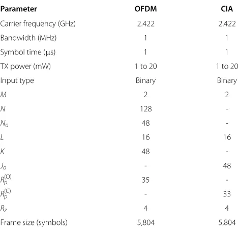
Table 2 User-defined parameters for the experimental setup
Parameter OFDM CIA
Carrier frequency (GHz) 2.422 2.422
Bandwidth (MHz) 1 1
Symbol time (µs) 1 1
TX power (mW) 1 to 20 1 to 20
Input type Binary Binary
M 2 2
N 128
-No 48
-L 16 16
K 48
-Jo - 48
R(O)p 35
-R(C)p - 33
Rz 4 4
Frame size (symbols) 5,804 5,804
Consequently, no estimator for the integer part offhas been implemented in this block [21]. In this regard, the time history of the resulting fˆ, depicted in Figure 6, shows a very stable and consistent behavior across the 100 performed tests.
As a result of the procedure described so far, the syn-chronized version of the received frame carrying the first (N +L)(1+R(pO) + NK˜o + Rz)+N received samples
after theˆtfth, defined asxˆ(O)∈ C(N+L)
1+R(pO)+NoK˜ +Rz
+N
, is obtained by taking
ˆ
x(tO)=e−j2πtˆfy˜
t. (20)
20 40 60 80 100
0 0.01 0.02 0.03 0.04
Estimation
Finally, the leadingN samples ofxˆ(O), i.e., the preamble,
are discarded and the resultingxˆ(O)∈C(N+L)
1+R(pO)+NoK˜ +Rz
is fed to the serial to parallel block.
5.2.2 Serial to parallel
This block yields XˆT = HppSCPT + W(O) ∈
C(N+L)×
1+R(pO)+NoK˜ +Rz
, stream matrix ready for the CP
removal operation, withW(O) ∈ C(N+L)×
1+R(pO)+NoK˜ +Rz
matrix collecting the overall effect of both the thermal noise and the residual interference generated by the sec-ondary transmission, if perfect CSI is not available at HT. In particular, themth element ofxˆ(O) is mapped to [XˆT]
m−(N+L)Nm+L,Nm+L .
5.2.3 CP removal
The CP removal block discards the first L rows of the matrixXˆ, to obtain a matrixXˆT,N, ready to be processed by the DFT block. We can represent this operation in matrix form by
ˆ
XT,N =BX, (21)
with B cyclic prefix removal matrix as defined in Section 2. representation of the received frame in the frequency domain. As for the transmitter, herein the matrix repre-sentation is adopted for the sake of compactness, whereas the actualN-point DFT is computed by means of vector-wise operations through the FFTW [22] C library.
5.2.5 Equalizer
At this stage, a channel equalization is performed to remove the effect of the channel on the received sig-nal and proceed to the decoding. The orthogosig-nality between the subcarriers [24] allow the adoption of a classical low-complexity ZF strategy to equalize the received frame, as typically done in OFDM receivers. First, the portion of the spectrum with no active sub-carrier is discarded from XˆF,N, to recover the received noisy version of S. Accordingly, we remove both the first and the last N−No CNo×Rz is the frequency domain representation of the received noisy version of the padding matrixZ.
Before the equalization, the receiver can have an approximate estimation of the average SNR experienced during the reception, i.e., SNR, by computing the ratio
between the energy of the preambleg and the energy of the AWGN, obtaining
Note that, this approximation is more suitable for medium and high SNR regime, due to the presence of a noise component in g. Thus, the precision of SNR depends on the size of g andZ, being more accurate for 1 <<
Rz. Subsequently, the receiver can exploit the
knowl-edge of P(O) and compute the equalizer matrix Hˆeq =
Then, the equalized version of the data matrix is obtained asDˆ(eqO)= ˆHeqDˆ(O), ending the equalization process.
5.2.6 Parallel to serial This block yields dˆ ∈ C carrying the received version of the digitally modulated symbol vectord, of size NK˜
o.
5.2.7 Constellation demapper
The constellation demapper implements the appropriate function to recover the received bit vectorbˆ, ending the receiver processing.
5.3 CIA transmitter
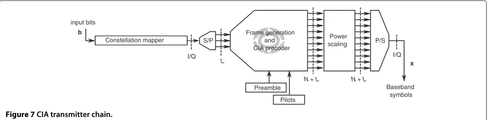
Consider the block representation in Figure 7. Differently from the OFDM transmitter in Figure 4, herein no IDFT or CP insertion block is present. Instead, a linear pre-coding is performed to the signal to project it onto the null-space of the interference channel hdsp, as discussed in Section 2. We note that, in the CIA transmitter, the precoding is performed at the frame generation stage for the sake of efficiency and compactnes; thus, these two operations are implemented in a single block, as shown in Figure 7. A detailed block-by-block description is pro-vided in the following.
5.3.1 Constellation mapper
This block provides the same functions as its previously described OFDM counterpart. In this case, we let b ∈ [0, 1]J be theJ-sized row input bit vector fed to the con-stellation mapper, such thatJ = logJ
2M ∈ N. Then, we let
S/P
Figure 7CIA transmitter chain.
5.3.2 Serial to parallel
This block provides the same functions as its previously described OFDM counterpart. Note that, the precoderE adopted in the following block operates on sequences of sizeL(i.e., dim ker Then, as before, a preliminary check on the size of d is performed. If LJ ∈/ N, a padding vector of dummy
, yielding a padded data row vector of size ˜
J=J. Finally, the data vectordis transformed into a data
matrixD(C)∈AL×L˜J, by mapping themth element ofdto
D(C)(m−Lm
L,mL+1). As before, we note thatLandJare user-defined parameters known at both ends of the com-munication and kept constant throughout the duration of the tests.
5.3.3 Frame generation and CIA precoder
This block is responsible for both the CIA frame gener-ation and linear precoding. The CIA frame includes four parts, namely a preambleg ∈ CN+L, a pilot matrixP(C) detailed in the following, the data matrixD(C)obtained as input after the serial to parallel conversion and a padding matrixZ=0(N+L)×Rz, withgandZobtained as described in Section 5.1. Note that, the sizes of the input symbol vec-tor of CIA and OFDM andLandN, respectively, do not coincide. Thus, the structure of the pilot matrix for CIA and OFDM, the latter being described in Section 5.1, is different. In this case, we letP(C)∈CL×R(pC), (withR(C)
p ≥L)
be a semi-unitary pilot matrix, such thatP(C)P(C)H= IL. In Section 5.4, we will see how this choice allows for a simpler channel estimation at CT.
Now, we recall that HT acts as an OFDM receiver dur-ing the uplink phase, as explained in Section 4. Durdur-ing this phase, a frequency domain estimation of the chan-nel towards OT, i.e.,hˆups = χhˆdsp, is acquired and stored.
The time domain version ofχhˆdsp, necessary to build the
circulant channel matrixχH˜dsp ∈ CN×(N+L) as in (4), is
then obtained by taking the IDFT ofχhˆdsp, and fed to the precoder block during the downlink phase, as shown in Figure 7. Subsequently, the efficient algorithms provided by the portable linear algebra library LAPACK [25] are exploited to compute the singular value decomposition (SVD) ofχH˜dspand select its right singular vectors
gener-ating ker(H˜dsp), to obtain the CIA precoderEsatisfying (7), as detailed in [3]. Finally, the CIA frame is constructed as
C=
where only the pilot and data matrices are precoded with E. We note that the preamblegis not precoded in order to preserve its useful properties in the time domain for syn-chronization purposes. The padding matrix does not need to be precoded, being entirely composed of null entries.
5.3.4 Power scaling
At this stage, a power scaling may be applied to shape a desired power profile for C before the parallel to serial operation. Letαg(C),αp(C),αd(C)∈Rbe parameters adopted
to scale independently the power ofg,EP(C)andED(C). In particular, the scaling parametersαg(C),αp(C)andαd(C) are
set such that the peak power of both the CIA and OFDM frames has the same order of magnitude. This choice has been made to guarantee that any interaction between the two signals at the receiver is due to their structure and not to favorable power levels of one signal w.r.t. the other. The frame obtained at the output of the power scaling block can be written asC =
5.3.5 Parallel to serial
We denote the output of the parallel to serial block
as x ∈ C(N+L)
1+R(pC)+L˜J+Rz
operation can be written as x(C) = vec(C)T, with x(C) being a row vector.
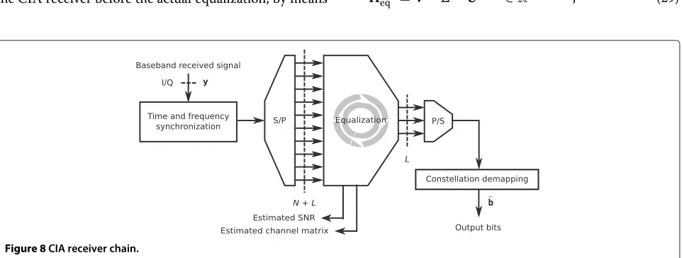
5.4 CIA receiver
Consider the block representation in Figure 8. The main difference between this scheme and the one presented for the OFDM receiver in Section 5.2 is the absence of the DFT and CP removal blocks. In fact, in the CIA receiver, no CP removal operation and DFT are required and the received signal can be directly equalized after an appropriate channel estimation. A detailed block-by-block description is provided in the following.
5.4.1 Synchronization
The synchronization block provides the same func-tions as its previously described OFDM counterpart.
The output of this block is xˆ(C)∈C(N+L)
1+R(pC)+L˜J+Rz
, synchronized and corrected vector carrying the first (N+L)
1+R(pC)+ JL˜ +Rz
samples after theˆtf +N
-th sample of the received vectory.
5.4.2 Serial to parallel
A serial to parallel conversion is performed on xˆ(C) to prepare the received stream for the channel estimation and equalization. The output of this block is the matrix
ˆ C =
ˆ
g EˆPˆ(C) EˆDˆ(C) Zˆ(C)
∈ C(N+L)×
1+R(pC)+L˜J+Rz
,
such that the mth element of xˆ(C) is mapped to
ˆ C
m−(N+L) m N+L,Nm+L
.
5.4.3 Equalizer
A channel estimation and a subsequent equalization are performed in this block, to remove the combined effect of channel and precoder on the received signal. We note that, an approximate estimation of the average SNR experi-enced during the reception, i.e.,SNR, can be computed by the CIA receiver before the actual equalization, by means
of (22) as explained in Section 5.2. The received frame can be rewritten as
ˆ C=
ˆ
g EˆPˆ(C) EˆDˆ(C) Zˆ(C)
(25)
=Hdss
g EP(C) ED(C) Z
+W(C), (26)
where the channel matrix Hdss has been isolated, for clarity. Note that, in (26), the matrix W(C) =
gW EWP(WC) EWD(WC) ZW
∈ C(N+L)×
1+R(pC)+JL˜+Rz
collects the overall effect of both the thermal noise and the interference generated by the OFDM transmission, withgW ∈ CN+L,EW ∈ C(N+L)×L,P(WC) ∈ C(N+L)×R
(C) p ,
D(WC)∈C(N+L)×LJ˜ andZW∈C(N+L)×Rz.
Let us consider an equivalent representation of the channel faced by the pilot and data matrices, given by the contribution of the CIA precoder and the actual channel. Let H(C) = HdssE ∈ C(N+L)×L be the equivalent chan-nel matrix. Then, an estimation of H(C) is computed in this block by evaluating the received pilot matrixPˆ(C) to obtain
ˆ
H(C)=(H(C)P(C)+P(WC))P(C)H (27)
=H(C)+ P(WC)P(C)H ! "# $ interference plus noise
, (28)
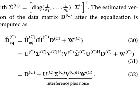
where the properties of the semi-unitary pilot matrixP(C) have been exploited. Now, letHˆ(C) = U(C)(C)V(C)H be the SVD of Hˆ(C), withU(C) ∈ C(N+L)×(N+L) and V ∈ CL×Lunitary matrices and = σ 0T, withσ = diag(σ1,. . .,σL) diagonal matrix carrying theLordered
singular values ofHˆ(C)and0 = 0
L×(N−L). Then, we can
obtainHˆ(eqC), ZF equalizer for the equivalent channel, as
ˆ
H(eqC)=V(C)˜(C)U(C)H∈RL×(N+L), (29)
with˜(C) =
diag(σ1
1,. . .,
1 σL)
0T. The estimated
ver-sion of the data matrix D(C) after the equalization is computed as
ˆ
D(eqC)= ˆH(eqC)(Hˆ(C)D(C)+W(C)) (30)
=U(C)(C)V(C)H(V(C)˜(C)U(C)HD(C)+W(C)) (31)
=D(C)+!U(C)(C)"#V(C)HW(C$) interference plus noise
. (32)
and this ends the equalization process.
5.4.4 Parallel to serial
A parallel-to-serial operation is performed on Dˆ(eqC) to
yield dˆ = vec
ˆ D(eqC)
T ∈ C˜J
L, row vector carrying the
received version of the digitally modulated symbol vector d, of size JL˜, ready to be fed to the constellation demapper.
5.4.5 Constellation demapper
The constellation demapper provides the same functions as its previously described OFDM counterpart. It imple-ments the appropriate function to recover the received bit vectorbˆ, ending the receiver processing.
6 Experimental results
In this section, we describe and discuss the results of the field tests performed to assess the performance of the proposed reconfigurable transceiver. Before we start describing the experimental setup, we would like to recall that the main objective of this work is to show the effec-tiveness of CIA as a means to manage interference in a practical setting. As seen in the previous sections, the actual packets transmitted include a lot of overhead and redundancy in terms of preamble and pilot usage. This is necessary to guarantee the good operation of the experi-ment, avoiding issues like poor synchronization and bad channel estimation to impede our proof-of-concept. At this stage of the research, priority has been given to the assessment of the practical feasibility of CIA and not on the obtained raw data rate. The latter will be the object of a further work.
In Figure 9, the environment hosting the field tests is depicted. Each USRP is driven by a PC that performs the baseband processing of the each transceiver, by execut-ing the flow graph representexecut-ing the transceiver chains, as described in Section 4. Differently from state-of-the-art contributions on the subject [8,10]) no backhaul is present in the environment, no data is shared among the devices and all the processing at the PCs is performed on the fly. For clarity, the operating mode of each device during the uplink and downlink phase is summarized in Table 1.
Finally, no object or person is moving inside the envi-ronment during the tests, unless otherwise specified. The parameters adopted throughout the test are described in Table 2.
We note that, the preamble size is identical in both OFDM and CIA chains, as seen in Sections 5.1 and 5.3. The first N + L samples of x, serialized version of the sum of the OFDM and CIA streams, i.e., S andC, are then obtained as the weighted sum of the OFDM and CIA preambles, identical by construction, with weights given by the power scaling factorsα(gO) andαg(C),
respec-tively. We remark that, this guarantees that OFDM and CIA signals are perfectly synchronized both at HT and OT (and CT).
We recall that, the effectiveness of the CIA precoder is strictly dependent on the reliability of the channel-state information, acquired by HT during the uplink phase. In practice, HT must be able to exploit the reciprocity of the uplink and downlink channels from the medium perspec-tive, i.e.,hdsp = χ1hups, inherent to TDD communications. Its responsiveness has be to such that uplink and downlink transmissions are performed within the coherence time of the channel.
6.1 Channel reciprocity
With the following experiment, we test the responsiveness of the transceiver in the considered scenario. Consider the three devices depicted in Figure 9. We focus on the pri-mary pair composed by HT and OT. Both devices engage in an OFDM transmission according to the procedure described in Section 4, and perform a channel estima-tion (uplink channel for HT and downlink channel for RX1), obtaining hˆupp and hˆdpp, respectively. Additionally, we let CT operate as an OFDM receiver that decodes the received signal and performs a channel estimation, obtaining hˆdps. We note that in our 1× 2 scenario,hdpp coincides with hdsp, whereas hdps coincides with hdss, by construction.
Cupboards
Brick wall
Glass windows
Hall
2 # P R S U 1
# P R S U
USRP #3 Room
Tables
Room
USRP #1: HT USRP #2: OT USRP #3: CT
Outdoor
Out door
Figure 9Environment hosting the field tests.
is almost identical. We note that, the negligible differ-ences between the uplink and downlink channels are due to several factors, such as estimation errors, small dif-ferences in the experienced SNR and the contribution of 1/|χ|to the considered channel gain, caused by the non-perfectly symmetric response of the RF circuitry in the two USRPs [14,15].
Conversely, no clear relationship is present betweenhˆdpp
and hˆdps, channel between HT and CT. The importance
Figure 10Time evolution of the channel gains (20th subcarrier out of the 48 occupied subcarriers).
of this result is twofold. On the one hand, we verified that the responsiveness of the proposed transceiver is such that the uplink and downlink channel reciprocity from the medium perspective holds in the considered scenario. On the other hand, the difference betweenhˆdppandhˆdpsproves that the CIA precoderEdesigned at HT to project to sig-nal onto the null-space precoder ofhdpp, would not incur interference cancelation effect when facinghdps. We note that this insight actively shows the feasibility of the CIA transmission, whose performance will be evaluated in the next section.
6.2 Performance evaluation
transmissions are required, to assess the performance of primary and secondary system. We first focus on the OFDM transmission, i.e., the link between HT and OT.
6.2.1 OFDM performance
Let us consider a stand-alone OFDM transmission per-formed by HT and OT, according to the parameters in Table 2, as if the secondary link was not present. A BPSK modulation is adopted for simplicity. A straightforward way to evaluate how the performance of the OFDM trans-mission may vary in presence or absence of the CIA transmission, is discussed in the following. First, an upper bound on the achievable throughput of the considered OFDM transmission, i.e., the maximum number of infor-mation bits that HT can transmit per second to OT, can be computed according to the parameters in Table 2. In this regard, if we letBbe the transmit bandwidth at HT then the maximum achievable throughput of the OFDM transmission can be computed as
To= NoB
(N+L)(R(pO)+R(O)z +NKo +1)
, (33)
that, in our case, corresponds to 8.13 kbps. We start noting that the value ofTo does not depend on the SNR. How-ever, the same is not true for the experimental throughput, defined herein asTˆo for clarity. In this regard, letρ ∈ R
be the average SNR at the receiver, an estimation of which is given bySNR in (22). As a matter of fact,Tˆo depends
onρ, given thatToˆ =ToNˆo(ρ)
No , withNoˆ (ρ)defined as the number of correct received bits. Consequently, the actual experimental throughput will always be lower or equal toTo.
The experimental throughput achieved by the actual OFDM transmission is computed for several experiments performed for different values of the SNR at the receiver. During our tests, the SNR variations at the receiver to obtain different experimental throughput values are user-induced. In practice, the transmit gain of the transmitting USRP is modified by the user when necessary, such that the transmit power may vary between 1 and 20 mW, for a resulting SNR at the receiving antenna ranging between 10 and 30 dB. Accordingly, as a first step, we compute the experimental throughput of the aforementioned stand-alone OFDM transmission, to obtain a specific benchmark to evaluate the performance of the primary transmission, when coexisting with the secondary CIA transmission. Afterwards, the CIA frame is generated and added to the transmit signal at HT to assess its impact on the experimental throughput of the primary transmission.
Concerning the CIA frame, we aim at validating the interference cancelation (reduction) capabilities of the precoderE. As a consequence, in our tests,Eis first com-puted from the estimation ofhˆupsperformed by HT during
each uplink transmission, then from a Rayleigh fading channel, randomly generated before each downlink trans-mission, according to the model described in Section 2. The rationale for this is that if the precoder built upon
ˆ
hups were not more effective than a randomly generated null-space precoder, then CIA would lose its attractive-ness, and there would be no use in further pursuing the development. The three so-obtained throughput curves are depicted in Figure 11. As previously mentioned, our proof-of-concept was not optimized to achieve the best rates but rather to show that CIA provides some effective interference protection. Therefore, we focus on a compar-ative analysis, i.e., a comparison between the performance obtained in presence of CIA w.r.t. to the stand-alone OFDM vase.
We note that the throughput loss experienced by the OFDM transmission when coexisting with the CIA trans-mission diminishes as the SNR increases ifEis built upon
ˆ
hups, whereas it increases with the SNR ifEis computed using the random channel realization. For the latter, the throughput is clearly interference-limited. Furthermore, we notice that for high SNR, i.e., larger than>20 dB, the experimental throughput of the OFDM transmission is very close to (if not coinciding with)To. Thus, despite the
imperfections due to the non-optimized practical imple-mentation, these findings show the effectiveness of the CIA precoder built upon the actual channel estimation, as a mean to protect the primary receiver from undesired interference.
We now perform a last test w.r.t. the primary transmis-sion and activate only the CIA transmitter chain at HT and switch our focus on the received power at OT after the CP removal operation and DFT. With this experiment, we aim at measuring the actual residual interference expe-rienced by OT, to better characterize the previous results.
10 15 20 25 30
7.8 7.85 7.9 7.95 8 8.05 8.1 8.15
SNR [dB]
Throughput [kbps]
Now, let M = QFB(HdppED(C) +W) ∈ CNo×LJ be the residual interference plus noise component at OT after the CP removal operation and DFT, with W ∈ CNo×JL matrix collecting the effect of the thermal noise,F,Band Hdppdefined in Sec. 2,EandD(C)defined in Sec. 5.3 and Qdefined in Sec. 5.2. Then, we introduce a metric called interference plus noise-to-noise ratio (INNR), as the ratio between the energy of the interference plus thermal noise component and the energy of the thermal noise, given by
INNR=10 log10
⎛ ⎜ ⎝ tr
MMH
tr
ˆ
Z(O)Zˆ(O)H
⎞ ⎟
⎠, (34)
withZˆ(O) as defined in Section 5.2. Note that, hereinE is derived according to the two aforementioned strate-gies, i.e., first the precoder is built upon the actual channel estimation then upon a random channel realization. As shown in Figure 12, the INNR for the randomly derived Eis significantly higher than the result for the actual CIA precoder, with the latter providing approximately 10 dB of interference isolation towards the OT, w.r.t. the former.
These findings confirm the previous results. However, we note that the INNR for the actual CIA precoder can reach up to 7 dB at high SNR. This shows the impact of both the lack of optimization in our implementation and possible hardware imperfections not properly compen-sated at software level on the quality of the acquired CSI, even for very favorable SNR values, i.e., SNR>20 dB.
6.2.2 CIA decoding
As a final test, we focus on the link between HT and CT to evaluate the performance of the secondary transmis-sion. We first perform a stand-alone CIA transmission using a previously built E, upon one of the many hˆups
10 15 20 25 30
0 2 4 6 8 10 12 14 16
SNR [dB]
INNR [dB]
Figure 12Residual interference at OT.
estimations, according to the parameters in Table 2. Sub-sequently, we follow an analogous approach to the test described in Section 6.2.1 and compute an upper bound on the achievable throughput of the considered CIA trans-mission, given the parameters in Table 2. Accordingly, we computeTc, maximum throughput of the CIA transmis-sion, i.e., the maximum number of information bits that HT can transmit per second to CT, as
Tc= JB
(N+L)R(C)p +R(C)z +JJ +1
, (35)
whose value is identical to the previous case, i.e., 8.13 kbps, due to the identical size of the OFDM and CIA frame by construction. Like before, we evaluate the experimental throughput achieved by the actual CIA transmission, i.e.,
ˆ
Tc, for several experiments performed for different values of the SNR at the receiver. In this regard, we recall the dependency of the experimental throughput on the aver-age SNR at the receiver, as discussed in Section 6.2.1. After the computation of the performance of the stand-alone CIA transmission, the impact of the primary transmission on the experimental throughput at CT is assessed by acti-vating the OFDM transmitter chain at HT. Therefore, the signal transmitted by HT for this test is the serialized ver-sion of the sum of the CIA and OFDM frame. The results of this test are provided in Figure 13.
The throughput of the secondary transmission is lower than the performance of the primary system, even though the difference is not large due to the adopted low mod-ulation order, i.e., BPSK. We note that, this finding con-firms the theoretical results in [5], showing that the CIA transmission achieves a non-negligible throughput w.r.t. OFDM. On the other hand, the presence of the OFDM transmission induces interference limited performance of the secondary system. Once again the performance loss
10 15 20 25 30
7 7.2 7.4 7.6 7.8 8 8.2
SNR [dB]
Throughput [kbps]
CIA standalone OFDM and CIA