Survey of Beam Steering Techniques Available for Millimeter
Wave Applications
Iyemeh Uchendu* and James Kelly
Abstract—Pattern reconfigurable antennas (beam steerable antennas) are essential for various applications in electronic engineering such as telecommunication and radar. They mitigate interference by channelling the antenna’s radiation to the direction of interest. This ability is vital for millimetre wave frequency applications such as small cell backhaul links where high path loss, attenuation from obstacles, and misalignment due to wind sway and accidents are prevalent. Several techniques have been used to implement beam steering over the years, most of which achieves steering at the expense of antenna performance. In this article, we surveyed the various techniques used in achieving beam steering and analyse each based on some figures of merit with the aim of identifying areas of improvements for each beam steering technique.
1. INTRODUCTION
Operation at millimetre wave frequencies has been proposed as a solution to the ever increasing demand for more bandwidth and higher data rates. The current microwave frequency spectrum suffers from congestion and cannot support the demand for higher data rate by mobile smartphone users due to the limitation of spectrum at these frequencies [1]. Spectrum, however, is in abundance at the millimetre wave frequencies as they are mostly unused. Millimetre wave frequency band refers to the frequencies between 30–300 GHz whose wavelengths range from 1 mm to 10 mm. The 10–30 GHz band is also sometimes referred to as millimetre wave frequency because energy at these frequencies have similar propagating characteristics to those at millimetre wave frequencies [2]. The millimetre wave frequency band is a promising candidate technology for realising key requirements which have been placed on next generation communication systems (5G), including higher data rates (estimated to be in Gbps) and higher aggregate capacity for supporting simultaneous users. It is hoped that 5G systems will also possess the following attributes: longer battery life, lower outage probability, and lower infrastructure costs [1]. However there are challenges associated with operating in the millimetre wave frequency band which have to be resolved for it to be used.
Three distinct challenges arise, as a result of the propagation characteristics, when operating at millimetre wave frequencies, these are: high free space path loss; absorption due to atmospheric gases and rainfall; and non-line of sight propagation. The free space path loss equation [3] is given by,
Lfsl = 92.4 + 20 logf + 20 logR (1)
wherefis frequency in GHz andRthe distance between antennas in km. This loss affects the link budget and becomes a huge challenge when transmitting over a large distance. Highly directive millimetre wave antennas are needed to overcome the high path losses for small cell backhaul applications. The distances between nodes in the backhaul network is likely to be a few meters [1].
Received 7 March 2016, Accepted 5 May 2016, Scheduled 14 May 2016 * Corresponding author: Iyemeh Uchendu (i.uchendu@surrey.ac.uk).
Absorption of energy from radio waves, due to atmospheric gases, reaches its peak value at a frequency of 60 GHz. The principal gases responsible for this effect are oxygen and water vapour. At this frequency, the signal attenuation is around 5 dB/km. At frequencies in this band, the size of rain drops, walls and objects are significant compared to the wavelength. For rain drops, the size introduces severe energy losses, depending on the magnitude of the rainfall [4]. This loss is characterised in terms of signal attenuation in dB/km, and consequently it can be reduced by shortening the transmission distance. For walls and objects, they become obstacles having high penetration losses at millimetre wave frequencies [1]. This forms the major challenge to the use of millimetre wave frequencies in 5G systems. To overcome this limitation, the antenna should have the ability to reconfigure its radiation pattern in order to avoid obstacles and maintain the link with other nodes in a network. This proposed solution introduces multiple challenges which must be resolved for 5G systems. The challenges are:
(i) Estimating the direction of arrival of the signals. This is vital as the system will need to know in which directions to reconfigure its beam.
(ii) Ability to differentiate between the desired signals and interference signals/jammers and supress them.
(iii) Reconfiguring its beam pattern to the new direction of interest to reduce the power dissipated in directions of non-interest and maintain high gain. There will also be a need to form multiple beams for point to multipoint applications.
Estimating the direction of arrival (DoA) is a major research area that is still developing. DoA estimation uses algorithms implemented at the base band level which weight signals from multiple antennas to determine the direction of the incoming signal. These algorithms can be classified into 3 broad groups: conventional beamforming, subspace-based techniques and maximum likelihood techniques [5]. Fig. 1 shows this classification along with subsets of each.
Figure 1. Classification of DoA techniques.
Reduction of the computational complexity and speed of these algorithm are one of the main focuses of DoA estimation research. For detailed overview of these techniques, see [5] and [6].
After estimating the direction of arrival of the signals, it becomes important to distinguish between the signal and jammers/interferences and then suppress them. This constitutes a wide research area that is heavily used in radar systems to distinguish a target from a jammer. Learning systems such as adaptive beamforming play a vital role in identifying signals in the midst of jamming/interference signals [7]. Many adaptive beamforming schemes have been implemented in literature to detect incoming signals of interest and they have been used to perform jammer suppression in [8] and [9].
This reduces the level of interference, improves the systems performance, and reduces the power used in transmission by channelling the radiation towards a specific direction.
Research in beam steerable antennas is generating lots of interest as efforts are being made to develop an optimum beam steering solution at millimetre wave frequency band for both point-to-point and point-to-multipoint applications. For point-to-multipoint applications, there will also be a need to be able to form highly directive multiple beams. In this article, we intend to survey the existing techniques that are been used to implement beam steering. In the next section, we will present figures of merit for the techniques, a way to evaluate their performance and rate them. In Section 3 we will discuss the techniques used to steer antenna beams. In Section 4, we will compare the steering techniques based on the figures of merit. In Section 5, we will conclude and present areas of improvement.
Figure 2. Illustrating beam steering.
2. FIGURES OF MERIT
To find the optimum beam steering technique, the following properties are vital:
(i) Insertion loss (IL): This is the loss that arises as a result of inserting a device in a transmission line. It is mathematically the difference between the power that goes in and the power that comes out of the device expressed in dB.
Insertion loss (dB) = 10 log Pin
Pout (2)
This is a critical figure of merit due to the fact that any technique that uses up most of the transmission power degrades the performance of the overall system. Also, lower insertion losses would imply lower energy requirement, which leads to better energy conservation.
(ii) Steering range: The maximum angle away from the bore sight direction to which the beam can be steered. The steering range depends on the radiating element. For example, a phased array made up of microstrip patch antennas cannot be steered over 360◦ by means of phase shifters due to the limitation of the element. While a monopole can be steered over 360◦ due to its omnidirectional radiation pattern. Hence, the steering range of techniques will be classified as either full range (based on the element) or a specific angle based on literature.
(iv) Steering speed: This is how fast the beam steering can be performed. The speed of steering determines the sensitivity of the technique and hence will determine if it is suitable for dynamic or static environment. The steering speed for a mobile user driving along the road will be different from that of a backhaul antenna that needs to switch its beam to a different node in the network. (v) Complexity: This takes into account the ease of implementing a technique. This also has a direct effect on the cost of implementing the technique. It will be rated as either high, moderate or low. (vi) Bandwidth phase deviation (BPD): This term refers to the uniformity of beam steering, as a
function of frequency, across the operating bandwidth of the antenna.
(vii) Size: The size of the manufactured device will determine the application that will make use of it. If it becomes very bulky, applications such as smartphones and tablets will not be able to accommodate it.
(viii) Cost: On a sales perspective, the cost of implementing a technique will influence the cost of the device.
3. BEAM STEERING TECHNIQUES
Lots of techniques have been used to steer an antenna’s radiation pattern over the years, including:
(i) Mechanical steering. (ii) Beamforming. (iii) Reflectarray. (iv) Parasitic steering.
(v) Integrated lens antennas (ILAs). (vi) Switched beam antennas. (vii) Traveling wave antennas. (viii) Retrodirective antennas.
(ix) Metamaterial Antennas.
3.1. Mechanical Steering
This involves manually turning the antenna to face the direction of interest. Mechanical steering becomes undesirable and difficult when we consider factors such as antenna size, weight, and weather conditions. Mechanical steering is often performed by means of electric motors. Recently, MEMS devices have been used to implement mechanical steering [11], they offer improved speed of scanning compared to manually steered arrays as well as low losses to the system. Mechanical steering is highly effective since it maintains the gain of the antenna and offers flexibility in the steering range of the antenna [12]. However, its use is limited to static or very slow changing environments due to the limitation in steering speed. Also, rotating mechanisms are prone to mechanical failure due to fatigue and wearing of moving parts [13]. The solutions for these problem led to electronic ways of steering beams.
3.2. Beamforming
3.2.1. RF/Analogue Beamforming
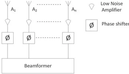
From Fig. 3, the signal from an element of the phased array is fed through a low noise amplifier after which the time delay is implemented by means of a phase shifter. The time delayed signals from each element are summed to produce the resultant beam by the beamformer. This method of beamforming is relatively cheap and low power when compared to digital beamforming [16]. However, it poses a challenge for applications having a large bandwidth requirement because the phase shifters are frequency dependent and produces variable phase shift across the bandwidth with accurate phase shift at the centre frequency [14]. This raises a limitation when used at millimetre wave frequencies where large bandwidth is fundamental. The combination of phase shifters connected to array elements is called a phased array which is the means used to steer the antenna beam.
Figure 3. RF/analogue beamforming architecture.
Phased arrays have been the conventional way of steering beams electronically to different directions within the range of the element pattern. By changing the phases of each element in the array with phase shifters, the combined beam of the array is steered. It has the advantage of high directivity, multiple beamforming (one at a time in different directions), fast scanning when compared to mechanical steering due to its electronic circuitry, and spatial filtering [17]. According to [18], a phase shifter is a control device that has a flat group delay versus frequency within its defined bandwidth of operation. Phase shifters could be digital or analogue. Analogue phase shifters are built with varactor diodes and offer continuous phase shift by controlling the voltage of the varactor diodes. This control voltage is highly influenced by noise and incurs heavy losses to the device. For this reason, digital phase shifters have received much attention due to their immunity to the noise present on voltage control lines. There are several techniques used to implement digital phase shifters, some of which are switched-line, loaded-line, reflection-type, and vector modulator technique phase shifters [18, 19].
authors stated that graphene transmission lines are low loss in the Terahertz frequency band. However the insertion losses were not measured and so it is impossible to ascertain how much loss these phase shifters will introduce into a system.
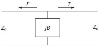
In the loaded-line technique, the transmission line is loaded with a capacitive reactance as shown in Fig. 4. This reactance is connected in shunt configuration. The reflection and transmission coefficients depend on the value of this impedance. Varying the impedance alters the reflection and transmission coefficients which determines the time delay, hence adjusting the load alters the phase shift experienced by the signal [18, 24]. The technique is used to achieve phase shifts of 45◦ or less and has the advantage of being compact [18]. The loaded line technique has been used at X-band frequencies and showed a maximum insertion loss of 1 dB and±2◦ phase errors at C-band frequencies (5 GHz to 6 GHz) [18]. This phase shifting technique is used in conjunction with others in order to improve the range and resolution of phase angle adjustment that can be achieved.
A reflection-type phase shifter typically consists of two impedance elements (Za and Zb), a 3-dB hybrid coupler and a switch as shown in Fig. 5. The impedance elements are connected across two ports of the 3-dB hybrid coupler by means of a single-pole, single-throw (SPST) switch. A schematic diagram is shown in Fig. 5.
Figure 4. Loaded-line phase shifter. Figure 5. Schematic of reflection-type phase shifter.
Table 1. Insertion losses of phase shifters.
Frequency Band (GHz) CMOS (dB) GaAs (dB) MEMS (dB) Ferrites (dB)
L (1–2) - 1.5–5.26 1.5–2.5 0.4
S (2–4) ≤1.5 4–7 ≥1.4 0.8
C (4–8) ≤5.6 ≤13 ≥2.6 3.6
X (8–12) ≤7.8 8.6–12.3 0.9–1.7 4.2
Ku (12–18) ≥3 ≥10.5 0.9–3.1 ≥4.2
K (18–27) ≤11 ≥5.3 0.4–3.5 4.3–7
Ka (27–40) 6–12 ≥9.1 2.7–5 ≥2
V (40–75) 6.91–17 ≥7.5 3.21–8.2
-W (75–110) 13–20 ≥8 ≥34.8
In the vector modulator technique, the input signal is fed into a quadrature power splitter which divides the signal into four vectors with 0◦, 90◦, 180◦, and 270◦ phase difference. A differential amplifier pairs the vector (0◦, 180◦) and (90◦, 270◦) [27]. The amplitude of each of the signals is weighted by variable attenuators and combined by the input modulator to obtain a phase-dependent vector sum [28]. In [27], a gain and phase variation of 0.1 dB and 0.8◦ respectively was achieved. [29] reported a gain and phase variation of 0.5 dB and±7◦ while achieving a 3-bit digital phase shift with a gain of 11.5 dB.
The key challenges associated with phase shifters in millimetre wave frequencies are:
(i) Losses incurred. (ii) Cost of phase shifters. (iii) Complexity of design.
Table 1 shows the insertion losses associated with some semiconductor based phase shifters. The table focuses on specific frequency bands and how the losses increase for each semiconductor device as frequency increases. The losses are given in ranges because they are dependent on several factors such as range of steering, resolution of steering and number of bits. MEMs and Ferrite based semiconductor phase shifters offer better insertion loss when compared to CMOS and GaAs phase shifters. The dashes (–) indicate values that could not be confirmed from literature.
3.2.2. Digital Beamforming
Figure 6. Digital beamforming architecture.
3.2.3. Hybrid Beamforming
Recently, interest is growing in a hybrid of analogue and digital beamforming that is intended to reduce the complexity of digital beamforming and improve the performance of analogue beamforming.
Based on Fig. 7, hybrid beamforming simply involves attaching digital beamforming architecture to the end of the RF/analogue beamformer. The RF/analogue beamforming section controls the phase of the signal at each element while the digital beamforming section applies applies baseband signal processing to enhance the performance of the multiple data channels [32].
Recent work in the area of RF beamforming have concentrated on reducing the losses associated with phase shifters. Currently, the major research interests in digital beamforming concentrate on algorithms to improve the computational time and signal tracking.
Figure 7. Hybrid architecture.
3.3. Reflectarray Antenna
A reflectarray is formed from the combination of a reflector and an array antenna. The aim, in combining the two technologies, is to utilise the strengths of each to maximum advantage. In a conventional parabolic reflector antenna, a field source is placed at the focus of a reflector as shown in Fig. 8. The field generated is then directed towards the point of interest by the reflector. In reflectarray antennas, the reflector is replaced with numerous reflector elements. Each element is separated by an identical spacing. The array is designed to redirect the incident waves. This is achieved by applying predefined phases to different sections of the array [33]. The predefined phases are either set actively, by using phase shifters or passively, by the shape and size of each element of the array. The phase shifters are connected to all the elements of the array [34].
Figure 8. Reflectarray.
3.4. Parasitic Steering
Figure 9 illustrates the construction of a Yagi-Uda antenna. The Yagi-Uda antenna consists of a single driven element surrounded by a number of passive elements. The term parasitic is used here to describe an element which is not supplied with energy but receives energy by means of electromagnetic coupling.
Figure 9. Schematic of Yagi-Uda antenna. Figure 10. Schematic of ESPAR antenna.
The parasitic element behind the driven element in Fig. 9 is called a reflector while the parasitic elements in front of the driven element are known as directors. Radiation propagates in the direction of the directors and by adding more directors it is possible to increase the directivity of the antenna. However, as the number of director increases, the electromagnetic coupling reduces and gets to a limit where adding directors have no effect on the directivity. Over time, the Yagi-Uda concept has developed from achieving highly directive pattern in one direction to directive patterns towards several angles of choice. A schematic diagram of a parasitic array structure is shown in Fig. 10.
monopoles and dipoles. Various configurations of antenna have been proposed in literature, these include Electrically Steerable Passive Array Radiators (ESPAR) [35], Circular Switched Parasitic Array (CSPA) [36], and disk-loaded monopole array antennas [37]. In [38], it is shown that the parasitic will have to be of close separation (within 0.1–0.5 wavelengths) to the active element in order to have good effects on the radiation pattern. This separation affects the mutual impedances between the parasitic and driven element and controls the steering angles that can be obtained.
The parasitics can be connected to the ground via a switch or with a variable reactor [35]. The parasitic acts as a reflector when it is short circuited to ground. When open circuited, the parasitic behaves as a director. The beam is steered towards the director as in the case of Yagi-Uda [36]. In the ESPAR and CSPA configurations the beam is steered in one plane. The orientation of the parasitics determine the plane in which the beam steering can occur.
Parasitic array steering has also been achieved using patch antennas, where a steering range of
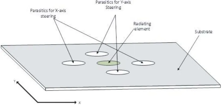
±30◦ has been reported [39]. The closer the parasitic is to the driven element, the larger the steering angle. However, the mutual impedance developed between the parasitic and driven element affects the reflection coefficient of the antenna. Based on the configuration of the parasitics around a patch antenna, steering could be achieved in one or two dimensions as demonstrated in [39] and [40] and shown in the Fig. 11.
Figure 11. Steering in two planes.
The parasitic elements along the x-axis can either act as director or reflector to steer the beam along thex-axis. The same applies for the parasitic element along they-axis, hence steering in 2 planes is achieved.
It is worth mentioning that most of the designs for parasitic steering involve only one driven element surrounded by a series of parasitics. In [41], tiny rectangular parasitic elements (pixels) were integrated into a linear array operating at a frequency of 5.6 GHz, which was an extension of [42] based on a single element. By setting up the parasitic pixels in a layer above the plane of the array, they achieved steering in two planes. The parasitic pixels were linked to each other by means of switches, this resulted in different switching configuration. Each driven element in the array had an array of parasitic pixels on a layer above it. This design increased the complexity and the number of switches needed to implement the design.
The authors in [43] achieved a wide steering angle of ±50◦ by reducing the ground plane and optimising the location of the switches for the parasitics. The design involved the use of a radiating element and 4 parasitics. The ground plane was reduced and covered half of the extreme parasitics on both sides of the radiating element. In [44], the authors integrated parasitics into a 3×1 phased array to improve the steering range and resolution of the phased array. This steered the array pattern by a maximum angle of ±15◦ without the use of phase shifters. Smaller steering angles were achieved depending on the combination of the parasitics.
the switches used in the antenna are lower when compared to other types of techniques because the switches are not inserted into the feeding network of the antenna. The authors in [45] compared the effect of two switches, BAR and HPND Pin Diode, on the radiation pattern of the parasitic array and noted some slight changes on beam direction. Hence, more study needs to be carried out on the use of a switch with variable impedance to observe how it affects the beam direction.
3.5. Integrated Lens Antennas (ILAs)
The concept of integrating a lens over a planar radiating element was developed by Rutledge [46] and has seen much improvement since then. From the schematic of an ILA in Fig. 12, it consists of a dielectric lens of an elliptical or quasi elliptical shape integrated with a set of driven elements. The elements of the array are offset by a specific distance, d, from each other and mounted at the back focal plane of the lens [33, 36, 47–51]. The lens is placed in a way that the radiation from each element appears to emanate from the same focal point and the elements are controlled by means of a switch, activating each element one at a time to implement the different predefined angles of steering [47, 50]. The ILA achieves a highly directional beam using fewer elements when compared with a phased array antenna. ILAs also employ RF switches instead of phase shifters which have lower losses, offer simplicity and lower cost when compared to phase shifters [48].
Figure 12. Schematic of an ILA.
In [51], the recorded steering ranges were ±35◦ and ±22◦ along with 0◦. The measurement was carried out on antennas that operated between 52 GHz and 68 GHz. Gains of up to 18.4 dBi were recorded for a 7.5 mm radius lens. The insertion losses associated with each switch were 2.5 dB. In [50], the ILA was extended to accomplish 2D steering by using a 2 dimensional 8 element array operating at 77 GHz. Scan angles of 17◦ and 25◦ were reported with gain of 16 dBi for 15 mm lens radius.
However, in order to achieve large steering angles the offset between each radiating element will increase. Increasing the offset of the radiating elements deteriorates the focusing properties of the lens [47] and increases the gain scan loss. The gain scan loss is defined as the difference in gain measured between the bore-sight beam direction and the steered beam direction. The gain scan loss depends on the ratio of offset, of the radiating elements, to the radius of the lens [52]. Energy will also be lost (or dissipated) within the materials used to fabricate the lens. The magnitude of these losses will depend on the type of materials used in manufacturing the lens [53]. The ILA does not maximise the use of all the radiating elements to improve gain since each radiating element is turned on individually. The gain achieved is the combined gain of a single element and the lens. This ILA concept was improved in [50] by adding elements in two dimensions to accommodate steering in two planes but the two dimension improvement still had the limitation of one active element at a time. Also, it only offers predefined steering angles which implies that the connection will be lost if the receiving antenna is displaced from its predefined position.
3.6. Switched Beam Antenna (SBA)
This is a technique where antenna elements are arranged to cover an angle range of interest [12]. Each element covers a section of the total range as shown in Fig. 13 and is turned on when there is a need to radiate in that particular direction. This arrangement is a bit similar to that of ILAs without the lens, with the main difference being that the elements of ILAs are placed in a straight line.
The arrangement in Fig. 13 enables beam switching in 8 different directions. The antennas are placed at the centre, with each antenna radiating in a different direction as represented by the arrows. However, this solution is inefficient due to high cost and redundancy. The reason for the redundancy is that 8 different feeding networks will be required for the antenna setup in Fig. 13 although only one of these is turned on at any given time. This redundancy is present for all operating cases except point to multipoint transmission, where more than one antenna element can be turned on simultaneously. However this scenario may lead to problems due to high mutual coupling between the antenna elements. This can become a challenge to resolve. Also, if the receiving antenna falls in the region between the sectors (the boundary between consecutive antennas), connectivity cannot be guaranteed, hence a need to have continuous beam steering in line with the sectors.
Figure 13. Schematic of 8-sector switched beam antenna.
3.7. Traveling Wave Antennas (TWA)
Antennas can be broadly classified as standing wave (resonant) antennas or traveling wave antennas. For resonant antennas, the voltage standing wave patterns are formed by reflections from the open end of the wire. This implies that the current along the line goes to zero at the open end of the line [20]. In the case of travelling wave antennas, the radiating element is terminated by a matched impedance and the current is formed by waves travelling in one direction (no reflections), hence producing uniform patterns in current and voltage. The radiating element could be multiple elements connected together, the resulting radiation pattern will then depend on the shape of each individual element. There are two categories of travelling wave antennas [20]:
(i) Surface (slow) wave antennas: This category is regarded as slow because the guided wave propagates with a phase velocity less than the speed of light in free space. Due to its speed, it does not radiate except at points of discontinuities such as feed point and termination regions. The discontinuities act as sources of radiation and they occur at the feeding port and the termination at the end. With surface wave antennas, it is difficult to produce highly directive radiation patterns and the patterns suffer from significant sidelobes. The desired location of the main beam is determined by the length of the antenna [54]. Examples of surface wave antennas are: helixes, dielectric slabs or rods, and corrugated conductors.
the beam is controlled by the phase constant while the beamwidth is controlled by the attenuation constant of the wave. The phase constant changes with frequency, hence the beam angle for leaky wave antennas is frequency dependent [54].
Travelling wave antennas can be used for wideband frequency scanning as they radiate at all the frequencies within the operating bandwidth [55], meaning different angles at different frequencies. However, beam steering can also be implemented for the main beam at a defined frequency in a number of ways.
(i) Dual feeding points: By feeding the antenna from two different points, one at a time, the beam direction is mirrored along the vertical plane that cuts through the centre of the antenna. This has been demonstrated in [56] and [57]. If both ports are fed at the same time, a boresight beam direction is obtained [56].
(ii) Parasitic effect/Slot loading: In [58], a leaky wave antenna was surrounded by an array of patches separated by a small distance from the antenna. Switches were used to short the patches to ground thereby changing the reactance around the antenna. By operating the switches in different states, the defined frequency beam was steered. The authors reported a phase difference of 16◦ in the main beam direction between all the patches turned OFF and ON. Similar work was carried out in [59] and reported a phase difference of 37◦ in the main beam direction between all the patches turned OFF and ON.
(iii) Using materials with adjustable properties: Materials, such as graphene and metamaterials have been used to steer the beam of leaky wave antennas at a fixed frequency. In [60] graphene was used as a High Impedance Surface that acts as a ground plane for leaky wave antennas to steer the beam by changing its conductivity. Metamaterial was used in [61] to steer the main beam by changing the phase gradient of the metamaterial.
The two categories of traveling wave antennas produce beams that can be steered. However, for them to be used at millimetre wave frequencies, two major limitations for each would have to be resolved. For the surface (slow) wave antenna, the difficulty of achieving highly directive beam patterns would need to be resolved. Highly directional beams are needed to overcome free space propagation loss, as mentioned earlier. Leaky (fast) wave antennas have a similar challenge as phase shifters in that its main lobe direction is frequency dependent which will be a huge concern when operating over a large bandwidth, as would be the case for millimetre wave frequency applications. This frequency dependence would cause the antenna to radiate in different directions at different frequencies within the operating band.
3.8. Retrodirective Arrays
Retro-directive is a term that implies redirecting anything backwards towards the origin. Any antenna array setup that has this ability of redirecting a signal backwards towards the source of the signal without any prior information of the location of the source is a retrodirective array. The idea of retrodirectivity is based on a corner reflector principle used in radar applications where a ray of light is redirected by using reflectors perpendicular to each other [62]. Retrodirective arrays are generating a lot of interest in the research community due to this unique ability and the relative design simplicity when compared to beamforming. There are two main architecture topologies for retrodirective arrays: Van Atta array and phase conjugating mixers architecture [63].
Figure 14(a) shows a schematic of the Van Atta array. It makes use of antenna pairs connected to each other in redirecting the signals. The antenna pairs are equidistant from the centre of the array. While one antenna acts as the receiver, the other transmits the phased signal back to the source. The phasing of the signal is achieved using the transmission line principle with the proper lengths needed to reverse the phase used as the distance between the pair [63]. The retrodirective array uses the phase reversal to transmit the signal back to the source. The length of the transmission lines connecting each pair of antennas are equal.
(a) (b)
Figure 14. Retrodirective array. (a) Schematic of Van Atta array. (b) Schematic of phase conjugate mixer.
with either double the frequency of the received signal or at an intermediate frequency. This offers a flexible structure and can be easily implemented. Other forms of implementing phase reversal in conjugation architecture are phase detection and digital techniques. These offer improved performance at the expense of cost and complexity [64].
The retrodirective array is suitable for use in fast changing environments and can be used for tracking objects in radar applications. However, it encounters a major limitation. Due to its ability to transmit towards the direction of the source, it will also transmit towards a signal of non-interest since it has no means of identifying which signal to transmit or not to transmit.
3.9. Metamaterial Antenna
The concept of Metameterials was proposed by Veselago in 1968 [65]. They are man-made structures that are designed to exhibit electromagnetic properties that cannot be achieved from natural occurring structures [66]. Metamaterial have become attractive as their effective permittivity and permeability can be tuned to positive or negative values [67]. With this property, its refractive index can be tuned using active elements such as diodes and transistors. This results in active metamaterials which have found wide use in steering an antenna’s radiation pattern without the use of complex designs of feeding network and phase shifters.
When used in antennas, metamaterials are realised by printing sub-wavelength metallic cells periodically on a substrate [66] and placed on a layer above the radiating element and used as a frequency selective surface (FSS). To achieve steering, the cells are loaded with varactors. By tuning each cell to different capacitance, the permeability and permittivity of the material changes hence changing the refractive index of the material. A number of steering ranges have been achieved. In [66], 40◦ steering angle was achieved by designing a Leaky Wave Antenna (LWA) using metamaterials. [67] achieved±30◦ with discrete steps of 7.5◦. This was done by placing metamaterial radome consisting of 8 layers over a 4×16 patch array designed at 4.7 GHz. The insertion loss from each layer of metamaterial is 1dB which is quite high for the system. This also presents a very bulky steering solution. Also [68] reported 30◦ of steering with a beamwidth of 12.5◦ and a limited steering resolution. In [69], 5 metamaterial layers were used over a horn antenna to achieve a maximum steering angle of ±30◦ with intermediate angles of 0◦, 10◦ and 20◦. The design was implemented at 5.3 GHz. In [70], in order to achieve wider steering angles, the authors made use of multiple radiating elements with different orientations, each with its own metamaterial section. They reported a steering angle of±56◦
authors provided a theoretical background of the possible range of steering the beam of the antenna using the metamaterial as lens, however there was no achieved range of steering either by simulation or measurement.
Using metamaterials to steer the antenna beam poses some challenges. Firstly, due to the proximity of the metamaterial layers to the radiation element, the reflection coefficient (S11) of the antenna is affected and the resonance frequency of the antenna is altered with each tuning state of the metamaterial surface. This can be seen from the reflection coefficient plots in [66–70]. This would imply that it would not be convenient to use metamaterial layers as a means of steering for specific narrowband frequency applications. Secondly, as mentioned earlier, as more metamaterial layers are added which increases the range of steering, the insertion loss also increase. Lastly, most authors claim that using metamaterials for steering is less complex when compared to phased array antennas, however integrating the active devices and biasing circuits into each cell of each layer and the multiple layers seems to be quite complex to achieve and a lot more difficult to fabricate.
Table 2. Comparison of beam steering techniques.
Technique IL S-Res Complexity BPD Size Cost
Mechanical None Continuous Low None Large Low
Analogue BF High Predefined Moderate High Medium High
Digital BF High Fine High - - High
Reflectarray Medium Predefined Moderate High Large High
Parasitic Low Predefined Low - Freq dependent Low
ILAs Low Predefined Low - Medium Low
SBA Medium Predefined Low None Large High
TWA None Continuous Low High Small Low
R-Arrays Low Fine Moderate - Medium Medium
Metamaterial High Predefined Moderate - Medium Medium
4. COMPARISON OF TECHNIQUES
Table 2 presents an overview of each steering technique available in literature and their properties based on some of the figures of merit discussed in Section 2. The dashes in the table refer to areas that have not been reported in literature.
Mechanical steering would have been the ideal means of beam steering since it does not incur insertion losses, and the antenna’s performance is not degraded at any point. However, the slow speed of steering compared to the electronic methods of steering is its major disadvantage. RF/analogue beamforming offers fast steering speed, but its range of steering depends on the type of antenna used. For instance, a microstrip patch antenna would not be able to steer beyond the front plane due to the presence of the ground plane. RF/analogue beamforming typically degrades the antenna’s performance by introducing insertion losses and a bandwidth phase deviation while steering due to the methods used in achieving group delays. Digital beamforming improves the resolution of antenna arrays. However, the cost and power requirement are very high. Based on the technique employed, digital beamforming can have either frequency variant or frequency invariant (no bandwidth deviation) beam steering [31].
Reflectarray uses both its shape and phase shifters for beam steering. It is limited to predefined steering resolution as RF/analogue beamforming. Its large size due to the use of thousands of array elements becomes a disadvantage.
Integrated lens antennas depend on the switching between various antenna elements to achieve steering. This introduces redundancy in the system as only one element is switched on at a time along with insertion losses for the switches that controls each element. ILAs also offer predefined steering resolutions and the performance of the system degrades while trying to achieve wider steering angles.
Switched beam antennas like ILAs introduce redundancies to the system for point to point connection. This influences the cost and size of the antennas. Like mechanical steering, there is no bandwidth phase deviation as the performance of the antenna is maintained over the range of steering. However, for point to multipoint links, mutual coupling becomes a factor that needs to be considered.
Traveling wave antennas offer continuous steering resolution over the operating frequency bandwidth of the antenna. Its range of steering is limited by the bandwidth of operation, as such a wideband traveling wave antenna has a larger steering range when compare to a narrowband traveling wave antenna. Traveling wave antennas are simple to implement as they are simply structures that radiates energy, hence no insertion losses.
Retrodirective arrays steering range is dependent on the type antennas used as the case with RF/analogue beamforming. They offer very fine steering resolution within their steering range as they radiate in the direction of the source. Retrodirective arrays have a simple architecture with a moderate complexity due to the presence of phase conjugate mixers. With regards to bandwidth phase deviation, the Van Atta arrays would have no phase deviation as it transmits back towards the source of the signal while the phase conjugate mixer antennas would depend on the local oscillator. However the bandwidth phase deviation for phase conjugate mixer architectures have not been studied.
Metamaterial can achieve continuous steering depending on the active device used. The metamaterial surface increases the overall size of the antenna making it larger in size when compared to the original antenna. It also has an increased complexity due to the baising circuits needed for the varactors for each unit cell contained in a layer. A single layer could have as much as 5×5 cells. Adding more layers of metamatrial also contributes to the increase in complexity and insertion loss of the system which could be as high as 1 dB per layer.
5. CONCLUSION
This paper discussed the major limitations that have to be resolved in order to use millimetre wave frequencies for 5G communication systems which are: high path loss, attenuation by objects, and misalignment of antennas. We also explained why beam steering is a solution to these limitations, as suggested in the literature. We presented the various beam steering techniques available from literature and compared them based on some figures of merit. Based on our study on beam steering techniques, the following are areas that require further research in beam steering techniques:
• Insertion loss of phase shifters at millimetre wave frequencies: A lot is yet to be known about the performance of phase shifters at millimetre wave frequencies. From the available literature, insertion loss of phase shifters increase as the frequency increases. With losses arising from free space path loss, additional losses from phase shifter would be a huge burden on the system. Hence, the need for phase shifters with lower insertion loss.
• Bandwidth phase deviation: The ability of a technique to steer the radiation pattern of an antenna uniformly over the operating bandwidth is vital at millimetre wave frequencies. Based on one’s personal perspective, bandwidth phase deviation could be an advantage or a disadvantage. An advantage in the sense that the antenna has a radiation towards different directions within the operating bandwidth for point to multipoint applications. A disadvantage in the sense that the antenna dissipates energy in directions of non-interest while steering. This is a major challenge with phased arrays and traveling wave antennas that would need to be resolved before they could be deployed in this application. Investigations into bandwidth phase deviation for other steering techniques need to be carried out to ascertain its implications for other techniques.
the antennas are misaligned due to wind sway and accidents. With the current steering techniques that have limited steering resolution, once the antenna is displaced out of the predefined steering angles, the connection is lost.
ACKNOWLEDGMENT
We would like to acknowledge National Information Technology Development Agency (NITDA) of Nigeria for funding this work. We would also like to acknowledge the support of the University of Surrey 5GIC (http://www.surrey.ac.uk/5gic) members for this work.
REFERENCES
1. Rappaport, T. S., R. Mayzus, Y. Azar, K. Wang, G. N. Wong, J. K. Schulz, M. Samimi, and F. Gutierrez, “Millimeter wave mobile communications for 5G cellular: It will work!,”IEEE Access, Vol. 1, 335–349, 2013.
2. Watson, P. A., “Propagation factors in millimetre-wave radio-system design,” Electron. Power, Vol. 23, 569, July 1977.
3. “Millimeter-Wave (MMW) Radio Transmission: Atmospheric Propagation, Link Budget and System Availability,” Light Pointe White Paper Series, 2010.
4. Weibel, G. E., and H. O. Dressel, “Propagation studies in millimeter-wave link systems,” Proc. IEEE, Vol. 55, No. 4, 1967.
5. Chen, Z., G. Gopal, and Y. Yu, Introduction to Direction-of-arrival Estimation, Artech House, Norwood, MA, USA, 2010.
6. Johnson, D. H., “The application of spectral estimation methods to bearing estimation problems,” Proc. IEEE, Vol. 70, No. 9, 1018–1028, Sept. 1982.
7. Maguer, A., “Detection of targets in presence of strong jammers by adaptive beamforming,” 1989 International Conference on Acoustics, Speech, and Signal Processing, ICASSP-89, Vol. 4, 2815– 2818, May 23–26, 1989.
8. Yongzhe, L., S. A. Vorobyov, and A. Hassanien, “Robust beamforming for jammers suppression in MIMO radar,”2014 IEEE Radar Conference, 0629–0634, May 19–23, 2014.
9. Shin, C., J. Ju, D. Kang, S. Choi, C. Lee, C. Cheong, J. Seo, T. K. Sarkar, and M. Salazar Palma, “Implementation of an antenna array for satellite communications with the capability of canceling jammers,” IEEE Antennas and Propagation Magazine, Vol. 55, No. 1, 32–48, Feb. 2013.
10. Bruce, E., and A. C. Beck, “Experiments with directivity steering for fading reduction,”Proc. IRE, Vol. 23, No. 4, 357–371, Apr. 1935.
11. Chiao, J., Y. Fu, I. M. Chio, M. DeLisio, and L. Y. Lin, “MEMS reconfigurable vee antenna,” IEEE MTT-S Int. Microw. Symp. Dig., Vol. 4, 1515–1518, 1999.
12. Baek, C. W., S. Song, C. Cheon, Y. Kim, and Y. Kwon, “2-D mechanical beam steering antenna fabricated using MEMS technology,” IEEE MTT-S Int. Microw. Symp. Dig., Vol. 1, 2001.
13. Rodrigo, D., L. Jofre, and B. A. Cetiner, “Circular beam-steering reconfigurable antenna with liquid metal parasitics,” IEEE Trans. Antennas Propag., Vol. 60, No. 4, 1796–1802, 2012.
14. Zarb-Adami, K., A. Faulkner, J. G. B. De Vaate, G. W. Kant, and P. Picard, “Beamforming techniques for large-N aperture arrays,” IEEE Int. Symp. Phased Array Syst. Technol., 883–890, 2010.
15. Van Veen, B. D. and K. M. Buckley, “Beamforming: A versatile approach to spatial filtering,” IEEE ASSP Magazine, Vol. 5, 4–24, 1988.
16. Steyskal, H., “Digital beamforming,”18th European Microwave Conference, 49–57, 1988.
17. Topak, E., J. Hasch, C. Wagner, and T. Zwick, “A novel millimeter-wave dual-fed phased array for beam steering,” IEEE Trans. Microw. Theory Tech., Vol. 61, No. 8, 3140–3147, 2013.
19. Nemati, M. H., M. Kaynak, and B. Tillack, “SiGe process integrated full-360◦ microelectrome-chanical systems-based active phase shifter for W-band automotive radar,”IET Microw. Antennas Propag., Vol. 8, No. 11, 835–841, 2014.
20. Balanis, C. A.,Antenna Theory: Analysis and Design, 3rd Edition, John Wiley &Sons Inc., Canada, 2005.
21. Cardoso, A. S., P. Saha, P. S. Chakraborty, D. M. Fleischhauer, and J. D. Cressler, “Lowloss, wideband SPDT switches and switched-line phase shifter in 180-nm RF CMOS on SOI technology,” IEEE Radio and Wireless Symposium (RWS), 199–201, 2014.
22. Zhang, J., S. W. Cheung, and Q. Zhu, “Design of 180◦-switched-line phase shifter with constant phase shift using CRLH TL,”IEEE Antennas and Propagation Society International Symposium (APSURSI), 344–345, 2014.
23. Chen, P. Y., C. Argyropoulos, and A. Alu, “Terahertz antenna phase shifters using integrallygated graphene transmission-lines,”IEEE Trans. Antennas Propag., Vol. 61, No. 4, 1528–1537, Apr. 2013. 24. Pozar, D., Microwave Engineering, 4th Edition, John Wiley &Sons Inc. 2005.
25. Atwater, H. A., “Reflection coefficient transformations for phase-shift circuits,” IEEE Trans. Microw. Theory Tech., Vol. 28, No. 6, 563–568, Jun. 1980.
26. Miller, D., S. Reiss, H. Masslert, A. Leuthert, and T. Zwick, “A H-band reflective-type phase shifter MMIC for ISM-band applications,”IEEE MTT-S International Microwave Symposium (IMS), 1–4, Jun. 2014.
27. Van den Bogaart, F. L. M. and R. Pyndiah, “A 10–14 GHz linear MMIC vector modulator with less than 0.1 dB and 0.8 degrees amplitude and phase error,”IEEE International Digest on Microwave Symposium, Vol. 1, 465–468, May 1990.
28. Ellinger, F. and W. Bachtold, “Novel principle for vector modulator-based phase shifters operating with only one control voltage,”IEEE J. Solid-State Circuits, Vol. 37, No. 10, 1256–1259, Oct. 2002. 29. Kim, S. J. and N. H. Myung, “A new active phase shifter using a vector sum method,” IEEE
Microw. Guid. Wave Lett., Vol. 10, No. 6, 233–235, Jun. 2000.
30. Godara, L. C., “Application of the fast fourier transform to broadband beamforming,”J. Acoust. Soc. Amer., Vol. 98, No. 1, 230–240, Jul. 1995.
31. Do-Hong, T. and P. Russer, “Signal processing for wideband smart antenna array applications,” IEEE Microw. Mag., Vol. 5, No. 1, 57–67, Mar. 2004.
32. Han, S., I. Chih-Lin, Z. Xu, and S. Wang, “Reference signals design for hybrid analog and digital beamforming,” IEEE Commun. Lett., Vol. 18, No. 7, 1191–1193, 2014.
33. Raisanen, A. V., J. Ala-Laurinaho, D. Chicherin, Z. Du, A. Generalov, A. Karttunen, D. Lioubtchenko, J. Mallat, A. Tamminen, and T. Zvolensky, “Beam-steering antennas at millimeter wavelengths,” 5th Global Symposium on Millimeter-Waves Proc., 170173, May 2012. 34. Antar, D. and Y. Guha, Microstrip and Printed Antennas: New Trends, Techniques and
Applications, John Wiley & Sons, Hoboken, NJ, USA, 2010.
35. Kawakami, H. and T. Ohira, “Electrically steerable passive array radiator (ESPAR) antennas,” IEEE Antennas Propag. Mag., Vol. 47, No. 2, 43–50, Apr. 2005.
36. Vilar, R., R. Czarny, M. L. Lee, B. Loiseaux, M. Sypek, M. Makowski, C. Martel, T. Crepin, F. Boust, R. Joseph, K. Herbertz, T. Bertuch, and J. Marti, “Q-band millimeter-wave antennas: An enabling technology for multigigabit wireless backhaul,” IEEE Microw. Mag., Vol. 15, No. 4, 121–130, Jun. 2014.
40. Jusoh, M., T. Aboufoul, T. Sabapathy, A. Alomainy, and M. R. Kamarudin, “Pattern reconfigurable microstrip patch antenna with multidirectional beam for WiMAX application,” IEEE Antennas Wirel. Propag. Lett., Vol. 13, 860–863, 2014.
41. Li, Z., S. Member, D. Rodrigo, L. Jofre, and B. A. Cetiner, “A new class of antenna array with a reconfigurable element factor,” IEEE Trans. Antennas Propag., Vol. 61, No. 4, 1947–1955, Apr. 2013.
42. Yuan, X., Z. Li, D. Rodrigo, S. Member, H. S. Mopidevi, O. Kaynar, L. Jofre, and B. A. Cetiner, “A parasitic layer-based reconfigurable antenna design by multi-objective optimization,” IEEE Trans. Antennas Propag., Vol. 60, No. 6, 2690–2701, Jun. 2012.
43. Sabapathy, T., M. Jusoh, R. B. Ahmad, and M. R. Kamarudin, “Wide angle scanning reconfigurable beam steering antenna,”2015 European Microwave Conference (EuMC), 14511454, Paris, 2015. 44. Uchendu, I. and J. Kelly, “Combined parasitic and phased array reconfigurable antenna,” 2015
Loughborough Antennas &Propagation Conference (LAPC), 1–4, Loughborough, 2015.
45. Sabapathy, T., R. B. Ahmad, M. Jusoh, M. R. Kamarudin, and A. Alomainy, “A pattern reconfigurable parasitic patch antenna using BAR and HPND PIN diode,”8th European Conference on Antennas and Propagation (EuCAP), 3444–3445, Apr. 2014.
46. Buttgenbach, T. H., “Improved solution for integrated array optics in quasi-optical mm and submm receivers: The hybrid antenna,” IEEE Trans. Microw. Theory Tech., Vol. 41, No. 10, Oct. 1993, 1750–1761.
47. Raisanen, A. V., J. Ala-Laurinaho, K. Haneda, J. Jarvelainen, A. Karttunen, M. Kyro, V. Semkin, A. Lamminen, and J. Saily, “Studies on E-band antennas and propagation,”Loughborough Antennas & Propagation Conference (LAPC), 176–180, Nov. 2013.
48. Artemenko, A., A. Maltsev, R. Maslennikov, A. Sevastyanov, and V. Ssorin, “Beam steerable quartz integrated lens antenna for 60 GHz frequency band,”Proc. 5th Eur. Conf. Antennas Propag., 758– 762, Apr. 2011.
49. Ala-Laurinaho, J., A. Karttunen, J. Saily, A. Lamminen, R. Sauleau, and A. V. Raisanen, “MMwave lens antenna with an integrated LTCC feed array for beam steering,” Proc. 4th Eur. Conf. Antennas Propag. (EuCAP), 2010.
50. Artemenko, A., A. Mozharovskiy, A. Maltsev, R. Maslennikov, A. Sevastyanov, and V. Ssorin, “2D electronically beam steerable integrated lens antennas for mmwave applications,” 42nd European Microwave Conference (EuMC), 213–216, Nov. 2012.
51. Artemenko, A., A. Maltsev, A. Mozharovskiy, A. Sevastyanov, V. Ssorin, and R. Maslennikov, “Millimeter-wave electronically steerable integrated lens antennas for WLAN/WPAN applications,” IEEE Trans. Antennas Propag., Vol. 61, No. 4, 1665–1671, Apr. 2013.
52. Filipovic, D. F., G. P. Gauthier, S. Raman, and G. M. Rebeiz, “Off-axis properties of silicon and quartz dielectric lens antennas,”IEEE Trans. Antennas Propag., Vol. 45, No. 5, 760–766, May 1997. 53. Lam, T. A., D. C. Vier, J. A. Nielsen, C. G. Parazzoli, and M. H. Tanielian, “Steering phased array antenna beams to the horizon using a buckyball NIM lens,” Proc. IEEE, Vol. 99, No. 10, 1755–1767, Oct. 2011.
54. Frezza, F., “Introduction to traveling-wave antennas,”European School of Antennas, 1–10, 2006. 55. Karmokar, D. K. and K. P. Esselle, “Periodic U-slot-loaded dual-band half-width
microstripleaky-wave antennas for forward and backward beam scanning,”IEEE Trans. Antennas Propag., Vol. 63, No. 12, 5372–5381, Dec. 2015.
56. Topak, E., J. Hasch, C. Wagner, and T. Zwick, “A novel millimeter-wave dual-fed phased array for beam steering,” IEEE Trans. Microw. Theory Tech., Vol. 61, No. 8, 3140–3147, Aug. 2013. 57. Khalil, M., M. Kamarei, J. Jomaah, and H. Ayad, “Compact SIW leaky wave antenna,” 2015
Third International Conference on Technological Advances in Electrical, Electronics and Computer Engineering (TAEECE), 124–129, Apr. 2015.
59. Karmokar, D. K., K. P. Esselle, and S. G. Hay, “Shifting the fixed-frequency beam scanning range of a leaky-wave antenna by slot loading,” 2014 IEEE-APS Topical Conference on Antennas and Propagation in Wireless Communications (APWC), 640–643, Aug. 3–9, 2014.
60. Wang, X., W. Zhao, J. Hu, and W. Yin, “Reconfigurable terahertz leaky-wave antenna using graphene-based high-impedance surface,” IEEE Transactions on Nanotechnology, Vol. 14, No. 1, 62–69, Jan. 2015.
61. Ghasemi, A., S. N. Burokur, A. Dhouibi, and A. de Lustrac, “Phase-gradient metasurfaces for beam steerable antennas,”2014 International Workshop on Antenna Technology: “Small Antennas, Novel EM Structures and Materials, and Applications” (iWAT), 191–194, Mar. 4–6, 2014.
62. Guo, Y.-C., X.-W. Shi, and L. Chen, “Retrodirective array technology,” Progress In Electromagnetics Research B, Vol. 5, 153–167, 2008.
63. Miyamoto, R. Y., and T. Itoh, “Retrodirective arrays for wireless communications,”IEEE Microw. Mag., Vol. 3, No. 1, 71–79, Mar. 2002.
64. Chen, L., Y. C. Guo, X. W. Shi, and T. L. Zhang, “Overview on the phase conjugation techniques of the retrodirective array,”Int. J. Antennas Propag., Vol. 2010, 2010.
65. Veselago, V. G., “The electrodynamics of substances with simultaneously negative values ofεand
μ,”Sov. Phys. Uspekhi, Vol. 10, No. 4, 509–514, Jan.–Feb. 1968.
66. Symeonidou, A. and K. Siakavara, “A novel microstrip antenna array with metamaterial-based electronic beam steering at 2.4 GHz,” Progress In Electromagnetics Research C, Vol. 38, 27–42, 2013.
67. Jiang, T., Z. Wang, D. Li, J. Pan, B. Zhang, J. Huangfu, Y. Salamin, C. Li, and L. Ran, “Low-Dc voltage-controlled steering-antenna radome utilizing tunable active metamaterial,” IEEE Trans. Microw. Theory Tech., Vol. 60, No. 1, 170–178, Jan. 2012.
68. Li, H., D. Ye, F. Shen, B. Zhang, Y. Sun, W. Zhu, C. Li, and L. Ran, “Reconfigurable diffractive antenna based on switchable electrically induced transparency,” IEEE Trans. Microw. Theory Tech., Vol. 63, No. 3, 925–936, Mar. 2015.
69. Pan, W., C. Huang, P. Chen, M. Pu, X. Ma, and X. Luo, A beam steering horn antenna using active frequency selective surface,” IEEE Trans. Antennas Propag., Vol. 61, No. 12, 6218–6223, Dec. 2013.
70. Dadgarpour, A., B. Zarghooni, B. S. Virdee, and T. A. Denidni, “Beam-deflection using gradient refractive-index media for 60-GHz nnd-Fire antenna,” IEEE Trans. Antennas Propag., Vol. 63, No. 8, 3768–3774, Aug. 2015.
71. Sun, F., Y. Ma, and S. He, “Two beam steering lenses enabled by metamaterials,” 2015 IEEE MTT-S International Microwave Workshop Series on Advanced Materials and Processes for RF and THz Applications (IMWS-AMP), 1–3, Suzhou, 2015.