Protecting the NOEKEON Cipher Against
SCARE Attacks in FPGAs by using Dynamic
Implementations
Julien Bringer1, Herv´e Chabanne1,2, Jean-Luc Danger2
1 Sagem S´ecurit´e
2 T´el´ecom ParisTech
Abstract. Protecting an implementation against Side Channel Analy-sis for Reverse Engineering (SCARE) attacks is a great challenge and we address this challenge by presenting a first proof of concept. White-box cryptography has been developed to protect programs against an adver-sary who has full access to their software implementation. It has also been suggested as a countermeasure against side channel attacks and we examine here these techniques in the wider perspective of SCARE. We consider that the adversary has only access to the cryptographic device through its side channels and his goal is to recover the specifications of the algorithm. In this work, we focus on FPGA (Field-Programmable Gate Array) technologies and examine how to thwart SCARE attacks by implementing a block cipher following white-box techniques. The pro-posed principle is based on changing dynamically the implementations. It is illustrated by an example on the Noekeon cipher and feasibility in different FPGAs is studied.
Keywords.SCARE attacks, white-box cryptography, FPGA.
1 Introduction
White-box cryptography has been introduced in the domain of Digital Rights Management with the ambitious goal of protecting keys of a block cipher while leaving to an adversary whole access to the software imple-menting this algorithm. Practically, this leads ciphers to be represented by a network of look-up tables. White-box implementations for DES and AES have been given in [2, 3]. These protections can affect either an encryption algorithm E (naked variant) or F o E o G where F and G are secret bijections. Today, there has been large cryptanalytic efforts on many implementations (naked or not) [1, 10, 12, 16, 18, 24].
this technique but in a different context. Our aim is now to protect a block cipher implemented in hardware. Moreover, we move from a white-box environment to a grey-box one where adversaries only get various side channels from the running algorithm (see for instance The Side Chan-nel Cryptanalysis Lounge, http://www.crypto.ruhr-uni-bochum.de/ en sclounge.html). The idea of using white-box cryptography as a pos-sible countermeasure against side channel attacks is not new. However, we consider here the situation where the adversary has not all the ele-ments of the algorithm in his possession and wants to recover the missing details by Side Channel Attack Reverse Engineering (SCARE).
SCARE was introduced in [19] with a proprietary algorithm for GSM phone. These results were improved by [4]. [9] studies DES in this context and is extended to Unknown Hardware Feistel Implementation by [20]. Use of proprietary algorithms and the protection of their specifications can be conceived in organizations that can afford the risk of relying on secret algorithms such as military groups or pay-tv / mobile network op-erators. Nevertheless, achieving an implementation which actually resists SCARE attacks is still a great challenge.
We explain why white-box cryptographic implementations indeed pro-vide an effective solution against SCARE. In particular, by constantly re-newing the look-up tables - as in classical counter-measures against side channels - we might reduce the side channels information on the specifi-cations of the running block cipher to almost nothing. We also underline that our proposal could be implemented on today’s chips as FPGAs and we illustrate this aspect with the cipher Noekeon [6].
The remainder of this paper is organized as follows. Section 2 explains why, in a theoretical model, dynamic white-box cryptography actually counteracts SCARE. Section 3 gives an overview of the Noekeon cipher. Section 4 focuses on practical aspects of our proposal where we illustrate our ideas by giving a complete FPGA implementation of the Noekeon cipher in this white-box context.
We emphasize that the reader should see this work as a first proof of concept. This might lead to a solution practically addressing the challenge of resisting SCARE.
2 Security Model and General Principle of our Protection
into a representation of look-up table network, namely a set of look-up tables {Tl}l∈L with some arcs between the tables (an arc corresponds to the output of one table becoming an input of another one). Then the look-up tables are obfuscated by encoding their input and output with encoding bijections; for instance Tl would be replaced by fout◦Tl◦fin. The choice of encoding functions of input and output is made according to the existing arcs between the tables so that the entire implementation does not change: if there is an arc fromTltoTl′, the output encoding ofTl
must be the inverse of the corresponding input encoding ofTl′. Encodings
at the same time of several tables gathered together are possible as well. From a side channel perspective, this implementation technique has yet some advantages. The implementation following a network of look-up tables does not give a direct access to the algorithm specifications and the main advantage is that a look-up table implementation improves the resistance against side channel analysis as the activity of the internal variables processed in the memory core are hardly discernible.
Remark 1. A look-up table access seems hard to exploit by Simple Power
Analysis and the resistance against Differential Power Analysis (DPA) is improved when the size of tables decreases. Indeed the size of the tables has an effect onto the DPA signal-to-noise ratio; this is illustrated for instance by [11].
2.1 Model
We detail here our security model and the corresponding assumptions. Following the previous remark, we consider that an adversary can obtain information on a look-up table neither by reading directly on it nor by measuring some signals during its execution. That is why we assume that a look-up table does not leak information by itself. However, we consider that the adversary can obtain information (partial or not) on the input and output of a look-up table execution. We assume that the adversary can make use of High-Order differential Side Channel Analysis (HO-SCA; introduced in [15,17] for High-Order DPA, see also [13]) to obtain several such information during an execution of the encryption algorithm.
generalized HO-SCA adversary as an HO-SCA adversary which is enabled to make several measures at the same step.
2.2 Our Protection in a Theoretical Nutshell
In a white-box implementation, an attacker can read at any moment of the execution the result provided by a look-up table, i.e. an encoded output f(x) (for some encoding function f), where x corresponds to a non-obfuscated intermediate result of the underlying cipher. In [18], the authors explain – under some conditions on the cipher structure – how this property can be exploited to recover the keys. In our context of grey-box attacks, the attacker would encounter more difficulties to read an entire result but the same situation may occur. To thwart this and at the same time to achieve security against SCA, we introduce a dynamic implementation by renewing the encoding bijections after each execution of the cipher. This is somewhat a generalization of [5] which applies a same random permutation to all the intermediate values during an AES execution in order to achieve first-order DPA resistance.
Given an encryption algorithm E which can be implemented as a network of look-up tables with the set of tables {Tl}l∈L, the implemen-tation at a timetis given by the tables {Tl[t] =fl,out[t]◦Tl◦fl,in[t]}l∈L.
After the implementation execution, a new set of random encoding bijec-tions{gl,in, gl,out} is chosen and the implemented tables are transformed into gl,out◦Tl[t]◦gl,in, i.e. the implementation of the tables evolves into
{Tl[t′
] = fl,out[t′
]◦Tl◦ fl,in[t′]}l∈L with fl,out[t′] = gl,out◦ fl,out[t] and
fl,in[t′] =fl,in[t]◦gl,in.
Remark 2. Constantly renewing the look-up tables might seem a very
costly solution but we explain later on in Section 4.5 why it might be fea-sible for practical hardware implementations. In our model, we moreover assume that the renewal process does not leak. Consequently, the adver-sary is seen here as a kind of constrained HO-SCA adveradver-sary. Note that a thorough practical analysis of the implementation would be necessary in the future to verify this claim. We thus see these points as an interesting challenge for further researches.
3 Noekeon Cipher [6]
We give here an overview of the Noekeon cipher. Noekeon was proposed to the NESSIE project in 2000 [6, 7, 14]. Noekeon is a 128-bit block ci-pher over 16 rounds. Noekeon maintains a state of four 32-bit words:
a0, a1, a2, a3. Each round is constituted by the following operations:
1. A first round constant is XORed toa0,
2. A linear transformation θ is applied to the four words a0, a1, a2, a3.
During the execution of θ, the round key is introduced by an XOR into the state.
Consider the involutive mapping that modifies four 32-bit words by XORing a linear transformation of the XOR of the other two words. This linear transformation consists of taking a word X, rotating it over a byte to the left to give Y and rotating it over a byte to the right to giveZ and XORingX, Y andZ,Z ←X⊕Y ⊕Z.θconsists of applying the described mapping, where the state words in odd positions are modified (X = a0 ⊕a2, Z is XORed to a1 and a3),
followed by XORing the key to the state, followed by again applying the described mapping, where the state words in even positions are modified.
For k the working key and a the state, each formed by four 32-bit words, the computation ofθ(k, a) is illustrated by Table 1.
Table 1.Computation ofθ(k, a)
temp←a0⊕a2; temp←temp⊕(temp >>8)⊕(temp <<8);
a1←a1⊕temp;
a3←a3⊕temp;
a0←a0⊕k0; a1←a1⊕k1; a2←a2⊕k2; a3←a3⊕k3;
temp←a1⊕a3; temp←temp⊕(temp >>8)⊕(temp <<8);
a0←a0⊕temp;
a2←a2⊕temp;
3. A second round constant is XORed toa0.
4. π1: The words a1, a2, a3 are rotated of 1, 5, and 2 bits, respectively,
to the left.
5. Γ: All bits in the same position ina0, a1, a2, a3 are grouped together
into nibbles (i.e. words of 4 bits) which go through the same non-linear bijectionγ (i.e. γ is applied 32 times, once for each possible nibble). 6. π2: The wordsa1, a2, a3 are rotated of 1, 5 and 2 bits, respectively, to
Finally, after the last round, a final constant is XORed toa0 and θis
applied.
To sum up, each round of the cipher can be decomposed in one non-linear step Γ and several linear ones. We have: 16 matrices Mj,
j = 1, . . . ,16 representing the steps 1 to 3 (from first round constant XOR to the second round constant XOR), one matrix for each round; 16 applications of π1,Γ and π2; and a matrix M′ =Mfinal for the final step
(the final constant XOR and the application ofθ).
4 Our Implementation of the NOEKEON Cipher
Compared to AES, Noekeon is a softer candidate for the technique we have introduced in Section 2.2, mainly due to the non-linear transforma-tion where the corresponding look-up table is smaller than for the AES. Nonetheless, it would be interesting to investigate its adaptation to other similar block ciphers.
4.1 General Description
Our implementation follows the strategy of Section 2 by the use of sev-eral tables look-up representation with the inclusion of input and output encoding functions to hide the key and the running values during com-putations.
Each of the 32 applications ofγ in the non-linear stepΓ of each round is implemented by a table look-up. A different 4×4 table is used for each
γ. Moreover, instead ofγ, our table represents fi◦γ◦gi−1, i= 0, . . . ,31 where thefi’s,gi’s are random bijections over nibbles. We need 16×32 = 512 different tables for the whole algorithm, which takes 512×24×4 bits (4KBytes). Following this, almost the whole implementation will operate on nibbles. We call the nibble of index i (for i ∈ {0, . . . ,31}), denoted
nibi, the nibble containing all the bits of index i of the current state
a0, a1, a2, a3, i.e. nibi = ai0a1iai2ai3 where aik denotes the i-th bit of ak. Onlyπ1,π2are seen as operations on bits. In fact, as rotations of different
order of the wordsa0, a1, a2,and a3, they correspond to permutations of
bits between nibbles and can be simply hardwired.
Concerning the 128× 128 binary matrices M1, . . . , M16 and M′, we
key, a nibble of the output state depends only on three nibbles of the input state. The corresponding formulas for the update ofnibi are given below (where the additions of index are taken modulo 32):T ai
0ai1ai2ai3
is updated as
0 B B B B B B B B B B B B B B B B B @ ai
0⊕k i 0⊕
“ ai
1⊕k i 1⊕a
i 3⊕k
i 3 ”
⊕
“
ai1+8⊕ki1+8⊕ai3+8⊕ki3+8”
⊕
“
ai1+24⊕ki1+24⊕ai3+24⊕ki3+24”
ai 1⊕
“ ai
0⊕a i 2 ”
⊕
“
ai0+8⊕ai2+8”⊕
“
ai0+24⊕ai2+24”⊕ki 1
ai2⊕k i 2⊕
“ ai1⊕k
i 1⊕a
i 3⊕k
i 3 ”
⊕
“ ai1+8⊕k
i+8 1 ⊕a
i+8 3 ⊕k
i+8 3
”
⊕“ai1+24⊕k i+24 1 ⊕a
i+24 3 ⊕k
i+24 3 ” ai 3⊕ “ ai
0⊕a i 2 ”
⊕
“
ai0+8⊕ai2+8”⊕
“
ai0+24⊕ai2+24”⊕ki 3 1 C C C C C C C C C C C C C C C C C A .
For instance,nib0is updated thanks to the input bits ofnib0,nib8 and
nib24. This enables us to split the representation of a such matrix into 32
smaller (4×12) binary matrices which take less room to be represented with look-up tables than a 128×128 binary matrix. For i∈ {0, . . . ,31}, the matrix used to update nibi at round j, as it would have been done by Mj, is denoted below byUji (j∈ {1, . . . ,16}) and the matrix used to updatenibi at the final step is denoted byUf inali .
The implementation of a 4×12 binary matrixU is realized as follows.
U is split into three 4×4 submatricesU[0],U[1], U[2] and the computa-tion of U.T(x0, . . . , x11) becomes U.T(x0, . . . , x11) =U[0].T(x0, . . . , x3) ⊕
U[1].T(x4, . . . , x7) ⊕U[2].T(x8, . . . , x11) where⊕corresponds to an XOR
on vectors of GF(2)4. Each U[l] is represented as a 4×4 look-up table,
for a size of 8 Bytes, and each XOR is seen as a 8×4 look-up table, for a size of 128 Bytes. Instead of considering 2 XOR of 8 inputs, a complexity reduction is achieved by using 4 XOR of 3 inputs as the size is only of 4 Bytes (8 Bytes if we consider the 4×4 look-up table as U[l]).
It leads to three 4×4 encoded look-up tables and one 4×4 encoded look-up tables (for the XORs). Thus, one 4×12 binary matrix is imple-mented on 32 Bytes. Note that the same input/decoding strategy as for
γ is also respected: random bijections over 4 bits are used at each 4 bits inputs and outputs of the tables.
By applying this method to all theUji(i∈ {0, . . . ,31},j∈ {1, . . . ,16}∪ {final}), we obtain 32×17×4 look-up tables of 4×4 size for an overall size of 32×17×32 Bytes, i.e. 17408 Bytes.
For this aim, we randomly choose an invertible 12×12 matrix M Bji
for each Ui
j, and instead of implementing directly the 5 look-up tables related toUji, we writeUji as the product of the two matricesUji.M Bji and (M Bij)−1. The implementation of Ui
j.M Bji as look-up tables is realized as explained above forUji and we add the implementation of the 12×12 matrix (M Bi
j)
−1by following the same principle, i.e. splitting into nine 4×
4 submatrices with the associated XOR and the additional input/output encodings. For one matrix (M Bji)−1, it gives 3 times the size ofUi
j.M Bji, i.e. 52224 Bytes.
With these representations of the matrices M1, . . . , M16, M′, Γ and
hardwired π1 and π2, the total number of 4×4 look-up tables is:
(M Bji)−1 : 32×17×12 Uji.M Bji : + 32×17×4
π2◦Γ ◦π1: + 32×16
This gives a total size of 73728 Bytes for all the 4×4 look-up tables.
4.2 Choice of Encoding Functions
The above description is made with the choice of random bijections as encoding functions. Although it is the classical strategy with static en-codings, our aim is to renew the encoding functions after each execution of the algorithm, which enables us to select bijective functions with a simpler representation.
Note also that all the input/output encoding functions are not fully independent because the output encoding function which acts on a nibble at one step must be followed by its inverse as the input encoding functions of the next operation on this nibble. In particular, as π1 and π2 operate
like permutation of bits between nibbles, the encoding functions have to be taken accordingly. For an easy compatibility of the encodings with these permutations, we design specific functions for the input and output encoding which are before or after the application ofπ1andπ2, i.e. around
γ, at the output of the Uji.M Bij (for j ∈ {1, . . . ,16}) and at the input of (M Bji)−1 (for j ∈ {2, . . . ,16} ∪ {final}). We design these encoding
functions f : GF(2)4 → GF(2)4 as an XOR with a random padding
cf = (cf,0, cf,1, cf,2, cf,3) – that isf(x) =x⊕cf – so that the inverse can be evaluated bit by bit. For instance, given all the output encoding functions
An example: The first look-up table forγ operates on the first nibble of the state. This nibble after permutation of the state byπ1 comes from
the bit 0 ofnib0, the bit 1 ofnib31, the bit 2 ofnib27and the bit 3 ofnib30.
If gji(x) = x⊕(cgi
j,0, cgji,1, cgij,2, cgij,3), then f
0
j is defined as fj0(x) = x⊕ (cg0
j,0, cgj31,1, cgj27,2, cg30j ,3). In the next section, we consider that encodings
for inputs of an XOR table are also chosen in this form. This enables us to lighten further the architecture.
Remark 3. Note that in our grey-box context, we can relax constraints on
the encoding functions as the adversary has no direct access to the look-up tables but only to their side channels. We here only have to periodically renew these tables and a simple linear mask might be sufficient to this purpose. Moreover, this simplifies the renewal (cf. end of Section 4.3).
4.3 Implementation Complexity in FPGAs
The FPGA architectures are based on Look-Up Tables (LUTs) which have at least 4 inputs (LUT4). LUT4 are well suited to implement the Noekeon algorithm as a 4×4 look-up table is implemented by 4 LUT4s. A first implementation consists in considering 32 parallel computations of nibbles at each round as explained in section 4.1. Figure 1 represents the corresponding architecture for one nibble path.
This gives a total of 36864 LUT4s for the whole function. This ar-chitecture can be optimized by considering eight parallel processings of four nibbles. Each bundle is composed of four nibbles
(nibi, nibi+8, nibi+16, nibi+24).
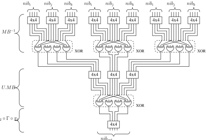
The architecture is composed of 8 bundle paths, a bundle path being illustrated by Figure 2. An advantage of this architecture is that all output encodings at the same level can be chosen independently thus leading to resistance against a generalized HO-SCA adversary (cf. Section 2).
There is 44 4×4 look-up tables for each bundle path. Hence the implementation requires a total of 23808 LUT4s for the whole Noekeon implementation (22528 for the 16 rounds and 1280 for the last round).
XOR XOR XOR
XOR
4x4
4x4
4x4 4x4 4x4 4x4 4x4 4x4 4x4 4x4
4x4 4x4
4x4
M B−1
nibi nibj nibk nibi nibj nibk nibi nibj nibk
U.M B
nibout π2◦Γ◦π1
Fig. 1.Architecture of the nibble path.
XOR XOR XOR XOR
4x4 4x4 4x4 4x4
4x4 4x4 4x4 4x4 4x4 4x4 4x4 4x4 4x4 4x4 4x4 4x4 4x4 4x4 4x4 4x4
4x4 4x4 4x4 4x4 4x4 4x4 4x4 4x4 4x4 4x4 4x4 4x4 4x4 4x4 4x4 4x4
XOR XOR XOR XOR
M B−1
nib16 nib24 nib8
nib0 nib0 nib8 nib16 nib24 nib0 nib8 nib16 nib24 nib0 nib8 nib16 nib24
nibc nibd
nibb
niba niba nibb nibc nibd niba nibb nibc nibd niba nibb nibc nibd
niba nibb nibc nibd
nibout24 nibout16
nibout8 nibout0
U.M B
π2◦Γ◦π1
128-bit register to store the intermediate results at each round, this gives a total of 2816FPGA cells of LUT4.
4.4 Feasibility in Current FPGAs
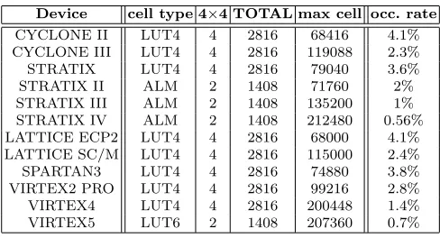
Most SRAM-based FPGAs (those from ALTERA, XILINX and Lattice for instance) [21–23] have cells composed of LUT4 but recent families have a more advanced cell structure. For instance the STRATIX II, III and IV from ALTERA take advantage of the Adaptive LUT Module (ALM) which could be configured as two independent LUT4. The VIRTEX 5 family from XILINX has six-input look-up (LUT6) which can output two signals. Table 2 summarizes the occupation percentage in the SRAM-based FPGA devices. Columns 4×4 and TOTAL indicate respectively the number of cells for the 4×4 table and the total number of cells for the proposed Noekeon implementation with the serial implementation. In the rightmost column the occupancy rate is indicated for the biggest devices. It remains relatively low and proves the white box feasibility of the Noekeon implementation in most FPGA devices.
Table 2.Occupation rate
Device cell type 4×4 TOTAL max cell occ. rate
CYCLONE II LUT4 4 2816 68416 4.1% CYCLONE III LUT4 4 2816 119088 2.3%
STRATIX LUT4 4 2816 79040 3.6%
STRATIX II ALM 2 1408 71760 2%
STRATIX III ALM 2 1408 135200 1% STRATIX IV ALM 2 1408 212480 0.56% LATTICE ECP2 LUT4 4 2816 68000 4.1% LATTICE SC/M LUT4 4 2816 115000 2.4%
SPARTAN3 LUT4 4 2816 74880 3.8%
VIRTEX2 PRO LUT4 4 2816 99216 2.8%
VIRTEX4 LUT4 4 2816 200448 1.4%
VIRTEX5 LUT6 2 1408 207360 0.7%
4.5 Dynamic implementation for encoding renewal
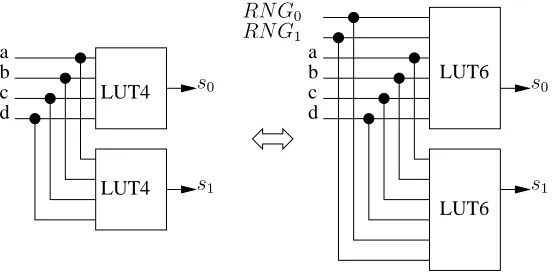
either completely or partially (only for the XILINX devices) [23] but the time needed for reconfiguration would reduce significantly the ciphering rate. Another solution – as a trade-off between practical and theoretical security – is to add extra pins to input random number values issued from a Random Number Generator (RNG) or ideally a True RNG (TRNG) [8] based on non deterministic physical phenomenon. The extra RNG pins do not add logic in some FPGAs as in ALTERA STRATIX II, III and IV [21]. The cost to implement a 4×4 look up tables is two ALMs (Adap-tive Logic Modules) as shown in Table 2. If two extra pins for random numbers are added, there is no supplementary cost as the ALM is able to implement two LUT6 having four common inputs, as illustrated in Figure 3.
a b c d
LUT4 LUT4
LUT6 LUT6 a
b c d
s0
s1 s1
s0 RN G0
RN G1
Fig. 3.Using two RNG pins does not add ALMs.
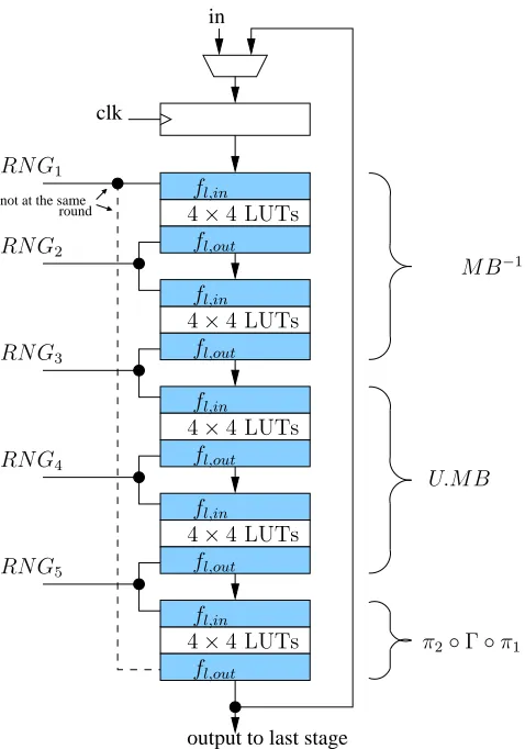
The global architecture is shown in Figure 2 with its 5 layers of look up tables. Hence there is a need of 5 TRNGs, one for each layer, the same RNG being used for fl,in and fl,out of adjacent look up tables as shown in Figure 4.
2 bits of entropy per nibble for encoding renewal allows the generation of 264×5different implementations per round. This implies a TRNG which
clk
round not at the same
in
output to last stage fl,in
fl,out
4×4 LUTs
fl,in
fl,out
4×4 LUTs
U.M B M B−1
RN G1
RN G2
RN G3
RN G4
RN G5
fl,in
fl,out
4×4 LUTs π2◦Γ◦π1
fl,in
fl,out
4×4 LUTs
fl,in
fl,out
4×4 LUTs
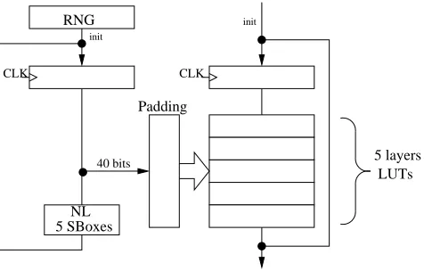
operation. At every round a specific sequence transforms the coding and allows to change the 40-bit RNG word. This RNG change allows to keep a high robustness level as the hamming distance between two rounds remains random. This RNG transformation can be based on a Non-Linear operation like a set of AES substitution boxes between two rounds. Five AES S-Boxes are needed in case of 40-bit TRNG seed. A padding stage is also necessary to feed correctly the encoding functions as explained in section 4.2. Figure 5 shows the general architecture of a Noekeon loop with the RNG and its associated processing.
5 SBoxes NL
Padding RNG
init
40 bits
init
5 layers LUTs
CLK CLK
Fig. 5.RNG processing Architecture.
If the clock frequency fclock is 50 MHz the TRNG data rate is of 40× fclock
17 = 118M bps. The number 17 comes from the 16 rounds plus
the final Noekeon step. Fast TRNGs like [8] can then be used for dynamic implementations of Noekeon.
5 Conclusion
be applied to other similar block ciphers as well. Nonetheless, the impact on a best-known cipher needs to be evaluated.
The look-up table renewal strategy based on TRNG is a key pro-tection feature. Some more work is still needed to validate the exact implementation cost and tune the level of protection provided by our solution according to the complexity. Other ways as on the fly FPGA reconfiguration in XILINX FPGAs could also be investigated. In particu-lar, the impacts on the efficiency and the exact overhead imposed by our dynamic reconfiguration must be measured on real implementations. Fur-ther works include also SCA through experiments to verify the efficiency of the countermeasure and to compare it to existing counter measures against SCARE attacks.
References
1. Olivier Billet, Henri Gilbert, and Charaf Ech-Chatbi. Cryptanalysis of a White Box AES Implementation. In Helena Handschuh and M. Anwar Hasan, editors,
Selected Areas in Cryptography, volume 3357 ofLNCS, pages 227–240. Springer, 2004.
2. Stanley Chow, Philip A. Eisen, Harold Johnson, and Paul C. van Oorschot. A White-Box DES Implementation for DRM Applications. InSecurity and Privacy in Digital Rights Management, ACM CCS-9 Workshop, DRM 2002, volume 2696 ofLNCS, pages 1–15. Springer, 2002.
3. Stanley Chow, Philip A. Eisen, Harold Johnson, and Paul C. van Oorschot. White-Box Cryptography and an AES Implementation. In Kaisa Nyberg and Howard M. Heys, editors,Selected Areas in Cryptography, volume 2595 ofLNCS, pages 250– 270. Springer, 2002.
4. Christophe Clavier. An Improved SCARE Cryptanalysis Against a Secret A3/A8 GSM Algorithm. InICISS, volume 4812 ofLNCS, pages 143–155. Springer, 2007. 5. Jean-S´ebastien Coron. A New DPA Countermeasure Based on Permutation Tables.
InSCN’08, volume 5229 ofLNCS, pages 278–292.
6. Joan Daemen, Micha¨el Peeters, Gilles Van Assche, and Vincent Rijmen. Nessie Proposal: NOEKEON, 2000.
7. Joan Daemen, Micha¨el Peeters, Gilles Van Assche, and Vincent Rijmen. On Noekeon, no!, 2001.
8. J-L Danger, S. Guilley, and P. Hoogvorst. High speed true random number gener-ator based on open loop structures in FPGAs. Elsevier Microelectronics Journal, doi: 10.1016/j.mejo.2009.02.004 2009.
9. R´emy Daudigny, Herv´e Ledig, Fr´ed´eric Muller, and Fr´ed´eric Valette. Scare of the des. InACNS, pages 393–406, 2005.
10. Louis Goubin, Jean-Michel Masereel, and Micha¨el Quisquater. Cryptanalysis of White Box DES Implementations. InSelected Areas in Cryptography, 14th Inter-national Workshop, SAC 2007, volume 4876 ofLNCS, pages 278–295. Springer, 2007.
12. Matthias Jacob, Dan Boneh, and Edward W. Felten. Attacking an Obfuscated Cipher by Injecting Faults. InSecurity and Privacy in Digital Rights Management, ACM CCS-9 Workshop, DRM 2002, volume 2696 ofLNCS, pages 16–31. Springer, 2002.
13. Marc Joye, Pascal Paillier, and Berry Schoenmakers. On second-order differential power analysis. In Josyula R. Rao and Berk Sunar, editors,CHES, volume 3659 ofLNCS, pages 293–308. Springer, 2005.
14. Lars R. Knudsen and Havard Raddum. On Noekeon, 2001.
15. P. Kocher, J. Jaffe, and B. Jun. Differential Power Analysis. InCRYPTO, volume 1666 ofLNCS, pages 388–397.
16. Hamilton E. Link and William D. Neumann. Clarifying Obfuscation: Improving the Security of White-Box DES. InITCC (1), pages 679–684. IEEE Computer Society, 2005.
17. Thomas S. Messerges. Using Second-Order Power Analysis to Attack DPA Resis-tant Software. InCHES, LNCS, pages 238–251. Springer-Verlag, 2000.
18. Wil Michiels, Paul Gorissen, and Henk D.L. Hollmann. Cryptanalysis of a Generic Class of White-Box Implementations. In Selected Areas in Cryptography 2008, 15th International Workshop, SAC 2008, 2008.
19. Roman Novak. Side-channel attack on substitution blocks. InACNS, pages 307– 318, 2003.
20. Denis R´eal, Vivien Dubois, Anne-Marie Guilloux, Fr´ed´eric Valette, and M’hamed Drissi. Scare of an unknown hardware feistel implementation. InCARDIS, pages 218–227, 2008.
21. Altera FPGA designer:http://www.altera.com/. 22. Lattice FPGA designer:http://www.latticesemi.com/. 23. Xilinx FPGA designer:http://www.xilinx.com/.
24. Brecht Wyseur, Wil Michiels, Paul Gorissen, and Bart Preneel. Cryptanalysis of White-Box DES Implementations with Arbitrary External Encodings. InSelected Areas in Cryptography, 14th International Workshop, SAC 2007, volume 4876 of