Available online: http://edupediapublications.org/journals/index.php/IJR/ P a g e | 582
Strengthening of Reinforced Concrete Beams using Glass
Fiber Reinforced Polymer Composites.
M.Parameswaraiah
1,
M.Mujahid Ahmad
2P.G. Scholar, Asst.Professor Department : Civil Engineering
Geethanjali College of Engineering and Technology
Email: 1 m.parameshsriram@gmail.com, 2mujahidcivilhod@gmail.com
.
Abstract
Around the world, a lot of research is as of now being directed concerning the utilization of fiber reinforced plastic envelops, overlays and sheets by the fix and fortifying of reinforced solid individuals. Fiber-reinforced polymer (FRP) application is an exceptionally compelling approach to fix and fortify structures that have turned out to be fundamentally powerless over their life expectancy. FRP fix frameworks give a monetarily reasonable option in contrast to conventional fix frameworks and materials.
Exploratory examinations on the flexural and shear conduct of RC beams fortified utilizing continuous glass fiber reinforced polymer (GFRP) sheets are completed. Remotely reinforced solid beams with epoxy-fortified GFRP sheets were tried to disappointment utilizing a symmetrical two point concentrated static stacking framework. Two arrangements of beams were threw for this trial test program. In SET I three beams frail in flexure were threw, out of which one is controlled bar and other two beams were fortified utilizing continuous glass fiber reinforced polymer (GFRP) sheets in flexure. In SET II three beams frail in shear were threw, out of which one is the controlled bar and other two beams were fortified utilizing continuous glass fiber reinforced polymer
(GFRP) sheets in shear. The reinforcing of the beams is finished with various sum and setup of GFRP sheets.
Test information on load, diversion and disappointment methods of every one of the beams were gotten. The detail system and use of GFRP sheets for fortifying of RC beams is additionally included. The impact of number of GFRP layers and its introduction on extreme load conveying limit and disappointment method of the beams are investigated.
Keyword:- Polymer, Fiber, Reinforced, Concrete, Polymer,
Introduction
Available online: http://edupediapublications.org/journals/index.php/IJR/ P a g e | 583
the examination of a few procedures for fixing or reinforcing purposes. One of the difficulties in reinforcing of solid structures is determination of a fortifying technique that will improve the quality and workableness of the structure while tending to confinements, for example, constructability, building activities, and spending plan. Structural reinforcing might be required because of a wide range of circumstances.
• Additional quality might be expected to take into account higher burdens to be put on the structure. This is frequently required when the utilization of the structure changes and a higher load-conveying limit is required. This can likewise happen if extra mechanical gear, documenting frameworks, grower, or different things are being added to a structure.
• Strengthening might be expected to enable the structure to oppose loads that were not foreseen in the first plan. This might be experienced when structuralstrengthening is required for burdens coming about because of wind and seismic powers or to enhance protection from impact stacking.
• Additional quality might be required because of an inadequacy in the structure's capacity to convey the first plan loads. Lacks might be the consequence of weakening (e.g., erosion of steel fortification and loss of solid section), structural harm (e.g., vehicular effect, exorbitant wear, intemperate stacking, and fire), or blunders in the first plan or development (e.g., lost or missing strengthening steel and insufficient solid quality). When managing such conditions, each project has its very own arrangement of confinements and requests. In the case of tending to space limitations, constructability confinements, toughness requests, or any
number of different issues, each project requires a lot of innovativeness in touching base at a reinforcing arrangement.
The dominant part of structural reinforcing includes enhancing the capacity of the structural component to securely oppose at least one of the accompanying interior powers caused by stacking: flexure, shear, pivotal, and torsion. Reinforcing is practiced by either decreasing the size of these powers or by upgrading the part's protection from them. Normal fortifying systems, for example, section amplification, remotely fortified fortification, post-tensioning, and supplemental backings might be utilized to accomplish enhanced quality and functionality.
Fortifying frameworks can enhance the opposition of the current structure to inner powers in either an inactive or dynamic way. Detached fortifying frameworks are normally connected just when extra loads, past those current at the time of establishment, are
connected to the structure. Holding steel plates or fiber-reinforced polymer (FRP) composites on the structural members are instances of aloof fortifying frameworks. Dynamic reinforcing frameworks ordinarily draw in the structure quickly and might be cultivated by acquainting outside powers with the part that balance the impacts of inward powers. Instances of this incorporate the utilization of outside post-tensioning frameworks or by jacking the part to ease or exchange existing burden. Regardless of whether uninvolved or dynamic, the principle challenge is to accomplish composite conduct between the current structure and the new fortifying components.
Available online: http://edupediapublications.org/journals/index.php/IJR/ P a g e | 584
thought of numerous variables including the accompanying engineering issues:
• Magnitude of solidarity increment; • Effect of changes in relative part
firmness;
• Size of project (techniques including unique materials and strategies might be less practical on little projects);
• Environmental conditions (techniques utilizing glues may be inadmissible for applications in high-temperature situations, outside steel strategies may not be reasonable in destructive conditions);
• In-put solid quality and substrate trustworthiness (the adequacy of strategies depending on attach to the current cement can be essentially restricted by low solid quality);
• Dimensional/freedom limitations (section broadening may be constrained by how much the expansion can infringe on encompassing clear space);
• Accessibility;
• Operational requirements (techniques requiring longer development time may be less alluring for applications in which building activities must be closed down amid development):
• Availability of materials, hardware, and qualified temporary workers;
• Construction cost, maintenance expenses, and life-cycle costs; and
• Load testing to confirm existing limit or assess new procedures and materials.
So as to stay away from the issues made by the consumption of steel support in solid structures, examine has shown that one could supplant the steel fortification by fiber reinforced polymer (FRP) fortification. Consumption of the steel fortification in reinforced cement (RC) structures influences the quality of both the steel and the solid. The quality of a consuming steel fortifying bar is diminished on account of a
decrease in the cross-sectional region of the steel bar. While the steel strengthening bars are consuming, the solid trustworthiness is disabled as a result of breaking of the solid cover caused by the extension of the consumption products.
The rehabilitation of infrastructures isn't new, and different projects have been done far and wide in the course of recent decades. One of the methods used to fortify existing reinforced solid members includes outer holding of steel plates by methods for two-part epoxy glues. By along these lines, it is conceivable to enhance the mechanical execution of a part. The wide utilization of this strategy for different structures, including buildings and extensions, has shown its productivity and its comfort. Disregarding this reality, the plate holding procedure shows a few weaknesses because of the utilization of steel as reinforcing material. The chief disadvantages of steel are its high weight which causes challenges in taking care of the plates nearby and its helplessness against destructive situations. In addition, steel plates have constrained conveyance lengths and, subsequently, they require joints.
PRESENT INVESTIGATION
Available online: http://edupediapublications.org/journals/index.php/IJR/ P a g e | 585
two beams were fortified by utilizing continuous glass fiber reinforced polymer (GFRP) sheets in shear.
STRUCTURAL INVESTIGATIONS
The historical backdrop of fortified outer fortification in the UK returns to 1975 with the reinforcing of the Quinton Bridges on the M5 motorway. This plan pursued various long stretches of improvement work by the Transport and Road Research Laboratory (TRRL), (now TRL), in relationship with glue producers and the Department of Transport. As far as testing projects, innovative work proceeded at the TRRL and at a few scholastic establishments in the UK, most outstandingly at the University of Sheffield. Hypothetical examinations and the assessment of reasonable cements were associated to the broad shaft testing programs which were embraced.
Primer examinations were directed by Irwin (1975). Macdonald (1978) and Macdonald and Calder (1982) revealed four point stacking tests on steel plated RC beams of length 4900mm. These beams were utilized to give information to the proposed fortifying of the Quinton Bridges (Raithby, 1980 and 1982), and fused two diverse epoxy cements, two plate thicknesses of 10.0mm and 6.5mm offering width-to-thickness (b/t) proportions of 14 and 22, and a plate lap-joint at its middle. In all cases it was discovered that disappointment of the beams happened toward one side by level shear in the solid nearby the steel plate, beginning at the plate end and bringing about sudden division of the plate with the solid still joined, up to about mid-length. The outside plate was found to have a considerably more noteworthy impact regarding break control and solidness. The heaps required to cause a split width of 0.1mm were expanded by
95%, while the diversions under this heap were
considerably lessened. The post breaking solidness was observed to be expanded by between 35– 105% relying on the kind of glue utilized and the plate measurements. The highlights of this work turned into the subject of a progressively nitty gritty program of research at the TRRL (Macdonald, 1982; Macdonald and Calder, 1982), in which a progression of RC beams of length 3500mm were tried in four point bending. The beams were either plated as-cast or plated subsequent to being stacked to deliver a most extreme split width of 0.1mm. The impact of augmenting the plate while keeping up its cross-sectional region steady was contemplated. It was discovered that the plated as-cast and the pre-split beams gave comparable load/deflection bends, exhibiting the adequacy of outside plating for reinforcing purposes.
A broad program of research work completed at the University of Sheffield since the late 1970s has featured various impacts of outer, epoxy-reinforced steel plates on the functionality and extreme load conduct of RC beams. A concise synopsis of a portion of the examination findings is exhibited by Jones and Swamy (1995).
Available online: http://edupediapublications.org/journals/index.php/IJR/ P a g e | 586
with which they were not in contact, for a separation to such an extent that the fortified zone (48000mm2)
was the equivalent for each plate width. The outer plate was not attached to the solid shaft aside from in the safe haven regions past the backings. The outcomes plainly demonstrated that thin plating was more successful than thick tight plating, as noted n studies led in the UK. The viable port length la which enabled the plate to achieve yield before shear disappointment adjoining the reinforced zones was observed to be contrarily relative to the b/t proportion. Along these lines, as b/t expanded (wide, thin plates), the jetty length diminished.
OBJECTIVES OF THE STUDY
• To study the flexural behavior of reinforced solid beams.
• To study the impact of GFRP fortifying on extreme load conveying limit and disappointment example of reinforced solid beams.
• To study the shear conduct of reinforced solid beams.
• To study the impact of GFRP fortifying on the shear conduct of reinforced solid beams.
EXPERIMENTAL STUDY
The experimental study consists of casting of two sets of reinforced concrete (RC) beams. In SET I three beams weak in flexure were casted, out of which one is controlled beam and other two beams were strengthened using continuous glass fiber reinforced polymer (GFRP) sheets in flexure. In SET II three beams weak in shear were casted, out of which one is the controlled beam and other two beams were strengthened by using continuous glass fiber reinforced polymer (GFRP) sheets in shear. The strengthening of the beams is done with varying configuration and layers of GFRP sheets. Experimental
data on load, deflection and failure modes of each of the beams were obtained. The change in load carrying capacity and failure mode of the beams are investigated as the amount and configuration of GFRP sheets are altered. The following chapter describes in detail the experimental study
CASTING OF BEAMS
Two sets of beams were casted for this experimental test program. In SET I three beams (F1, F2 and F3) weak in flexure were casted using same grade of concrete and reinforcement detailing. In SET II three beams (S1, S2 and S3) weak in shear were casted using same grade of concrete and reinforcement detailing.
STRENGTHENING OF BEAMS
Before bonding the composite fabric onto the concrete surface, the required region of concrete surface was made rough using a coarse sand paper texture and cleaned with an air blower to remove all dirt and debris. Once the surface was prepared to the required standard, the epoxy resin was mixed in accordance with manufacturer’s instructions. Mixing was carried out in a plastic container (Araldite LY 556 – 100 parts by weight and Hardener HY 951 – 8 parts by weight) and was continued until the mixture was in uniform colour.
Available online: http://edupediapublications.org/journals/index.php/IJR/ P a g e | 587
the fabric with the roller. Air bubbles entrapped at the epoxy/concrete or epoxy/fabric interface were to be eliminated. Then the second layer of the epoxy resin was applied and GFRP sheet was then placed on top of epoxy resin coating and the resin was squeezed through the roving of the fabric with the roller and the above process was repeated. During hardening of the epoxy, a constant uniform pressure was applied on the composite fabric surface in order to extrude the excess epoxy resin and to ensure good contact between the epoxy, the concrete and the fabric. This operation was carried out at room temperature. Concrete beams strengthened with glass fiber fabric were cured for 24 hours at room temperature before testing.
Fig. 3.10 Application of epoxy and hardener on the beam
Fig. 3.11 Fixing of GFRP sheet on the beam
Fig. 3.12 Roller used for removal of air bubbles
Analytical Study INTRODUCTION
This chapter is devoted to the development of an analytical model to analyse and design reinforced concrete beams strengthened in flexural by means of externally bonded glass fiber reinforced polymer composite sheets. The purpose of this analytical model is to accurately predict the flexural behavior of reinforced concrete beams strengthened with GFRP sheet.
FLEXURAL STRENGTHENING OF BEAMS
Available online: http://edupediapublications.org/journals/index.php/IJR/ P a g e | 588 Fig. 4.2 Flexural strengthening of beam using FRP
sheets at the bottom
Fig. 4.3 Stress Strain diagram of singly reinforced beam strengthen with FRP
CALCULATION OF MOMENT OF RESISTANCE OF THE BEAMS
The moment of resistance of the SET I beams are obtained from the following calculations:
fck = 31 MPa
b = 200 mm fy = 415 N/mm2
Ast = 226.19 mm2
As per IS: 456 : 2000, Clause 38.1, ANNEX G, the total force due to compression is equal to the total force due to tension, hence
C = T Cc = Ts
0.36 X fck X XU X b = 0.87 X fy X Ast XU = 36.59 mm
MU = 0.36 X fck X XU X b (d - 0.42 X XU) MU = 17.12 KN - m
Hence, the moment of resistance of beam F1 is 17.12 KN - m.
Now considering the effect of strengthening of beam F2 using two layers of GFRP sheets, so along with the tensile force Ts
an addition tensile force Tfrp will be also acting.
The value of Tfrp = ffrp X Afrp i.e. stress of GFRP X area of GFRP. The value of ffrp is obtained from the experimental testing.
ffrp = 334.5 N/mm2 Afrp = 120 mm2 C = T
Cc = Ts + Tfrp
0.36 X fck X XU X b = 0.87 X fy X Ast + ffrp X Afrp XU = 54.54 mm
MU = 0.36 X fck X XU X b (d - 0.42 X XU)
MU = 24.6 KN - m
Hence the moment of resistance of beam F2 is 24.6 KN - m . Due to application of two layers of GFRP sheet at the soffit of the F2 beam, the moment of resistance of the beam F2 is higher than moment of resistance of beam F1. The depth of neutral axis and the moment of resistance of both the beams is presented in table 4.1.’
Table 4.1 Analytical calculations of beams F1 and F2
Available online: http://edupediapublications.org/journals/index.php/IJR/ P a g e | 589
philosophy of strengthening rectangular RC beams, is equally applicable to other shapes such as T- and I-sections having non-prestressed reinforcement.
ASSUMPTIONS
The accompanying suspicions are made in computing the flexural opposition of a section fortified with a remotely connected FRP framework:
1) Design counts depend on the genuine measurements, inside fortifying steel course of action, and material properties of the current part being reinforced;
2) The strains in the fortification and cement are specifically relative to the separation from the nonpartisan hub, that is, a plane section before loading stays plane in the wake of loading; 3) There is no relative slip between outer
FRP support and the solid;
4) The shear misshapening inside the glue layer is ignored since the cement layer is thin with slight varieties in its thickness;
5) The greatest usable compressive strain in the solid is 0.003;
6) The elasticity of cement is dismissed; and
7) The FRP fortification has a direct flexible pressure strain relationship to disappointment.
RESULTS AND DISCUSSIONS
This section depicts the trial aftereffects of SET I beams (frail in flexure) and SET II beams (powerless in shear). Their behavior all through the static test to disappointment is depicted utilizing recorded information on avoidance behavior and a definitive load conveying limit. The split examples and the method of disappointment of each bar are likewise portrayed in this section.
Two arrangements of beams were tried for their definitive qualities. In SET I three beams (F1, F2 and F3) frail in flexure are tried. In SET II three beams (S1, S2 and S3) powerless in shear are tried. The beams F1and S1 were taken as the control beams. It was seen that the beams F1 and S1 had less load conveying limit when contrasted with that of the remotely reinforced beams utilizing GFRP sheets. In SET I beams F2 is reinforced just at the soffit of the bar and F3 is fortified up to the unbiased pivot of the bar alongside the soffit of the pillar. SET II beams S2 is reinforced just along the edges of the bar in the shear zone and S3 is fortified by U-wrapping of the GFRP sheets in the shear zone of the pillar. Avoidance behavior and a definitive load conveying limit of the beams were noted. A definitive load conveying limit of the considerable number of beams alongside the idea of disappointment is given in Table 5.1.
FAILURES MODES
The flexural and shear quality of a section relies upon the controlling disappointment mode. The accompanying flexural and shear disappointment modes ought to be investigated for a FRP-fortified section:
• Crushing of the solid in pressure before yielding of the strengthening steel; • Yielding of the steel in pressure pursued
by burst of the FRP cover;
• Yielding of the steel in pressure pursued by solid squashing;
• Shear/pressure delamination of the solid (cover delamination); and
• Debonding of the FRP from the solid substrate (FRP debonding).
Available online: http://edupediapublications.org/journals/index.php/IJR/ P a g e | 590
shear disappointment, flexural disappointment due to GFRP crack and pulverizing of cement at the best. Solid pounding is accepted to happen if the compressive strain in the solid achieves its most extreme usable strain. Burst of the FRP cover is accepted to happen if the strain in the FRP achieves its plan break strain before the solid achieves its most extreme usable strain. Cover delamination or FRP debonding can happen if the power in the FRP can't be continued by the substrate. So as to forestall debonding of the FRP overlay, a restriction ought to be set on the strain level created in the cover.
The GFRP reinforced shaft and the control beams were tried to discover their definitive load conveying limit. It was discovered that the control beams F1 and S1 bombed in flexure and shear demonstrating that the beams were deficient in flexure and shear separately. In SET I pillar F2 flopped because of break of GFRP sheet in two pieces and afterward flexural-shear disappointment of the shaft occurred. Bar F3 bombed because of delamination of the GFRP sheet after that break of GFRP sheet occurred and afterward flexural-shear disappointment of the shaft. In SET I beams F2 and F3, GFRP break and flexural-shear sort of disappointment was noticeable when fortifying was finished utilizing both the wrapping plans. In SET II beams S2 and S3 flopped due to flexural disappointment and pulverizing of cement on the highest point of the bar. The SET II beams S2 what's more, S3 created major flexural breaks at a definitive burdens. In SET II beams S2 and S3 the flexural sort of disappointment was unmistakable when reinforcing was finished utilizing both the wrapping plans.
LOAD DEFLECTION HISTORY
The heap redirection history of the considerable number of beams was recorded. The mid-length redirection of each beam was contrasted and that of their individual control beams. Likewise the heap avoidance behavior was analyzed between two wrapping plans having a similar support. It was noticed that the behavior of the flexure and shear deficient beams when reinforced with GFRP sheets were superior to anything their relating control beams. The mid-length diversions were much lower when reinforced remotely with GFRP sheets. The charts contrasting the mid-range redirection of flexure and shear deficient beams and their
Available online: http://edupediapublications.org/journals/index.php/IJR/ P a g e | 591
soffit of the beam. In SET II when both the wrapping plans were viewed as it was discovered that the beam S3 with U wrapping of GFRP sheet had a superior load avoidance behavior when contrasted with the beam S2 with GFRP sheet just along the edges of the beam.
Beam F1 was the control beam of SET I beams which were powerless in flexure however solid in shear. In beam F1 fortifying was not done. Two point static stacking was done on the beam and at the every addition of the heap, avoidance at the left, right and center dial checks were taken. Utilizing this heap and avoidance of information, stack versus diversion bend is ploted. At the heap of 30 KN beginning splits began going ahead the beams. Further with increment in stacking engendering of the breaks occurred. The beam F1 bombed totally in flexure.
Available online: http://edupediapublications.org/journals/index.php/IJR/ P a g e | 592
The load conveying limit of the control beams and the reinforce beams were discovered and is appeared in fig. 5.11 and 5.12. The control beams were loaded up to their extreme loads. It was noticed that of the considerable number of beams, the reinforce beams F2, F3 and S2, S3 had the higher load conveying limit contrasted with the controlled beams F1 and S1. An imperative character to be seen about the utilization of GFRP sheets is the high flexible behavior of the beams. The shear disappointment being sudden can prompt colossal harm to the structure. Be that as it may, the bendable behavior gotten by the utilization of GFRP can give us enough cautioning before a definitive disappointment. The utilization of FRP can defer the underlying breaks and further improvement of the splits in the beam.
From the load and deflection of information
of SET I beams F1, F2 and F3, load versus deflection bend is ploted for all the three beams. From this load versus deflection bend, unmistakably beam F1 has bring down extreme load conveying limit contrasted with beams F2 and F3. Beam F1 had likewise experienced higher deflection contrasted with beams F2 and F3 at a similar load. Beam F2 had higher extreme load conveying limit contrasted with the controlled beam F1 yet lower than beam F3. Beam F3 had higher extreme load conveying limit contrasted with the beams F1 and F2. Both the beams F2 and F3 had experienced relatively same deflection upto 65 KN load. After 65 KN load beam F3 had experienced same deflection as beam F2 yet at a higher load contrasted with beam F2. The deflection experienced by beam F3 is most noteworthy. Beam F2 had experienced higher deflection than beam F1.
COMPARISION OF RESULTS
Available online: http://edupediapublications.org/journals/index.php/IJR/ P a g e | 593
not permitted to build up a thorough hypothetical plan approach. The multifaceted nature of the issue has then made essential a broad exploratory research. Snapshot of obstruction of the SET I beams was determined systematically and was contrasted and the got test results
Beam S2 of SET II beams which were powerless in shear yet solid in flexure. In beam S2 fortifying is finished by use of GFRP sheet just on the opposite sides of the beam. Two point static loading was done on the beam and at the every addition of the load, deflection at the left, right and center dial measures were taken. Utilizing this load and deflection of information, load versus deflection bend is ploted. At the load of 39 KN introductory splits began going ahead the beams. Introductory splits began at a higher load in beam S2 contrasted with beam S1. Further with increment in loading spread of the splits occurred. In beam S2 just flexural splits were created lastly the beam bombed by flexural disappointment and squashing of cement. Beam S2 conveyed an extreme load higher than beam S1 yet lower than beam
S3.
Available online: http://edupediapublications.org/journals/index.php/IJR/ P a g e | 594
From the load and deflection of information of SET II beams S1, S2 and S3, load versus deflection bend is ploted for all the three beams. From this load versus deflection bend, unmistakably beam S1 has bring down extreme load conveying limit contrasted with beams S2 and S3. Beam S1 had additionally experienced higher deflection contrasted with beams S2 and S3 at a similar load. Beam S2 had higher extreme load conveying limit contrasted with the controlled beam S1 however lower than beam S3. Beam S3 had higher extreme load conveying limit contrasted with the beams S1 and S2. Both the beams S2 and S3 had experienced relatively same deflection upto 70 KN load. After 70 KN load beam S3 had experienced same deflection as beam S2 yet at a higher load contrasted with beam S2. The deflection experienced by beam S3 is most elevated. Beam S2 had experienced higher deflection than beam S1.
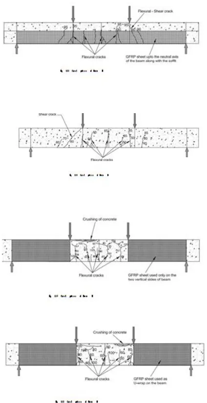
Crack Pattern
The crack patterns at fall for the tried beams of SET I and SET II are appeared in Fig. 5.13 to 5.18. In SET I the controlled beam F1 showed generally separated and lesser number of cracks contrasted with reinforced beams F2 and F3. The fortified beams F2 and F3 have likewise indicated cracks at generally close separating. This demonstrates the improved solid
constrainment because of the GFRP reinforcing. This composite activity has brought about moving of disappointment mode from flexural disappointment (steel yielding) in the event of controlled beam F2 to stripping of GFRP sheet if there should be an occurrence of reinforced beams F2 and F3. The debonding of GFRP sheet has occurred due to flexural-shear cracks by giving cracking sound. A crack ordinarily starts in the vertical course and as the load builds it moves slanted way because of the joined impact of shear and flexure. On the off chance that the load is expanded further, cracks propagate to top and the beam parts. This sort of disappointment is called flexure-shear disappointment.
Available online: http://edupediapublications.org/journals/index.php/IJR/ P a g e | 595 COMPARISION OF RESULTS
The results of the two set of beams tested are shown in Table 5.1. The failure mode, load at initial crack and ultimate load of the control beams without strengthening and the beams strengthen with two layers GFRP sheet are presented. The difficulties inherent to the understanding of strengthen structural member behavior subjected to flexure and shear have not allowed to develop a rigorous theoretical design approach. The complexity of the problem has then made necessary an extensive experimental research. Moment of resistance of the SET I beams was calculated analytically
and was compared with the obtained experimental results
Table 5.2 Comparision of Mu value obtained
from analytical and experimental study
Conclusion
In this exploratory examination the fl exural and shear behavior of reinforced solid beams fortified by GFRP sheets are contemplated. Two arrangements of reinforced cement (RC) beams, in SET I three beams feeble in flexure and in SET II three beams powerless in shear were threw and tried. From the test outcomes and determined quality qualities, the accompanying ends are drawn:
A) SET I Beams (F1, F2 and F3)
1. Initial flexural splits show up at a higher load by reinforcing the beam at soffit. A definitive load conveying limit of the reinforce beam F2 is 33 % more than the controlled beam F1.
2. Load at beginning breaks is additionally expanded by fortifying the beam at the soffit and on the opposite sides of the beam up to the unbiased pivot from the soffit. A definitive load conveying limit of the fortify beam F3 is 43 % more than the controlled beam F1 and 7 % more than the reinforce beam F2.
Available online: http://edupediapublications.org/journals/index.php/IJR/ P a g e | 596
4. When the beam isn't reinforce, it flopped in flexure yet in the wake of fortifying the beam in flexure, at that point flexure-shear disappointment of the beam happens which is more perilous than the flexural disappointment of the beam as it doesn't give much cautioning before disappointment. In this way it is prescribed to check the shear quality of the beam and complete shear reinforcing alongside flexural fortifying whenever required.
5. Flexural reinforcing up to the nonpartisan hub of the beam builds a definitive load conveying limit, however the splits created were not unmistakable up to a higher load. Because of imperceptibility of the underlying splits, it gives less cautioning contrasted with the beams fortify just at the soffit of the beam.
6. By reinforcing up to the unbiased hub of the beam, increment in a definitive load conveying limit of the beam isn't critical and cost contribution is very nearly three times contrasted with the beam fortify by GFRP sheet at the soffit as it were.
B) SET II Beams (S1, S2 and S3)
1. The control beam S1 bombed in shear as it was made deliberately powerless in shear.
2. The beginning breaks in the fortify beams S2 and S3 shows up at higher load contrasted with the un-reinforce beam S1.
3. After fortifying the shear zone of the beam the underlying breaks shows up at the flexural zone of the beam and the split enlarges and propagates towards the impartial pivot with increment of the load. The last disappointment is flexural disappointment which shows that the GFRP sheets increment the shear quality of the beam. A definitive load conveying limit of
the reinforce beam S2 is 31 % more than the controlled beam S1.
4. When the beam is fortify by U-enclosing by the shear zone, a definitive load conveying limit is expanded by 48 % contrasted with the control beam S1 and by 13% thought about the beam S2 reinforce by holding the GFRP sheets on the vertical sides alone in the shear zone of the beam.
5. When the beam is fortify in shear, at that point just flexural disappointment happens which gives adequate cautioning contrasted with the weak shear disappointment which is cataclysmic disappointment of beams.
6. The holding between GFRP sheet and the solid is unblemished up to the disappointment of the beam which obviously demonstrates the composite activity due to GFRP sheet.
7. Restoring or redesigning the shear quality of beams utilizing GFRP sheet can result in expanded shear quality and solidness with no unmistakable shear splits. Reestablishing the shear quality of beams utilizing GFRP is an exceedingly powerful system.
Reference:-
1. M. A. Shahawy, M. Arockiasamy, T. Beitelman, R. Sowrirajan “Reinforced concrete rectangular beams strengthened with CFRP laminates” Composites: Part B 27B (1996) 225-233
2. Victor N. Kaliakin, Michael J. Chajes and Ted F. Januszka “Analysis of concrete beams reinforced with externally bonded woven composite fabrics” Composites: Part B 27B (1996) 235-244
3. Koji Takeda, Yoshiyuki Mitsui,
Kiyoshi Murakami, Hiromichi Sakai and
Moriyasu Nakamura “Flexural
Available online: http://edupediapublications.org/journals/index.php/IJR/ P a g e | 597 strengthened with carbon fibre sheets”
Composites Part A 27A (1996) 981-987 4. G. Spadea, F. Bencardino and R. N.
Swamy “Structural Behavior of Composite RC Beams with Externally Bonded CFRP” Journal of Composites for Construction Vol. 2, No. 3. August, 1998. 132-137
5. Ahmed Khalifa, William J. Gold, Antonio Nanni, and Abdel Aziz M.I. “Contribution of externally bonded FRP to shear capacity of RC flexural members” Journal of Composites for Construction, Vol. 2. No. 4, November,1998. 195-202 6. N. F. Grace, G. A. Sayed, A. K.
Soliman and K. R. Saleh “Strengthening Reinforced Concrete Beams Using Fiber Reinforced Polymer (FRP) Laminates” ACI Structural Journal/September-October 1999. 865-875
7. B. Taljsten and L. Elfgren
“Strengthening concrete beams for shear using CFRP- materials: evaluation of different application methods” Composites: Part B 31 (2000) 87–96
8. Ahmed Khalifa, Antonio Nanni
“Improving shear capacity of existing RC T-section beams using CFRP composites” Cement & Concrete Composites 22 (2000) 165-174
9. Thanasis C. Triantafi llou and Costas P. Antonopoulos “Design of concrete flexural members strengthened in shear with FRP” Journal of Composites for Construction, Vol. 4, No. 4, November, 2000. 198-205
10. V.P.V. Ramana, T. Kant, S.E.
Morton, P.K. Dutta, A. Mukherjee and
Y.M. Desai “Behavior of CFRPC
strengthened reinforced concrete beams with varying degrees of strengthening” Composites: Part B 31 (2000) 461-470 11. D. Kachlakev and D.D. McCurry
“Behavior of full-scale reinforced concrete beams retrofitted for shear and flexural with FRP laminates” Composites: Part B 31 (2000) 445-452
12. Alex Li, Cheikhna Diagana, Yves Delmas “CRFP contribution to shear capacity of strengthened RC beams” Engineering Structures 23 (2001) 1212–1220
13. J. F. Bonacci and M. Maalej
“Behavioral trends of RC beams
strengthened with externally bonded FRP” Journal of Composites for Construction, Vol. 5, No.2, May, 2001, 102-113
14. Ahmed Khalifa, Antonio Nanni
“Rehabilitation of rectangular simply
supported RC beams with shear
deficiencies using CFRP composites” Construction and Building Materials 16 (2002) 135–146
15. Bjorn Taljsten “Strengthening
concrete beams for shear with CFRP sheets” Construction and Building Materials 17 (2003) 15–26
16. C. Diagana, A.Li, B. Gedalia, Y. Delmas “Shear strengthening effectiveness with CFF strips” Engineering Structures 25 (2003) 507–516
17. M.N.S. Hadi “Retrofi tting of shear failed reinforced concrete beams” Composite Structures 62 (2003) 1–6
18. Sergio F. Brena, Regan M.
Bramblett, Sharon L. Wood, and Michael E. Kreger “Increasing Flexural Capacity of Reinforced Concrete Beams Using Carbon Fiber- Reinforced Polymer Composites” ACI Structural Journal/January-February 2003. 36-46
19. Bimal Babu Adhikary, Hiroshi
Mutsuyoshi, and Muhammad Ashraf
“Shear Strengthening of Reinforced Concrete Beams Using Fiber-Reinforced Polymer Sheets with Bonded Anchorage” ACI Structural Journal/September-October 2004. 660-668
20. Zhichao Zhang and Cheng-Tzu