Wide Bandwidth Horizontally-Polarized Omnidirectional Antennas
for Indoor Distributed Antenna System Applications
Lei Zhou*, Yong-Chang Jiao, Chi Zhang, Yihong Qi, and Tao Ni
Abstract—Three horizontally-polarized (HP) omnidirectional antennas are proposed and discussed in this paper. The antennas are composed of 3, 4 or 5 printed dipoles with corresponding wideband 3-, 4-or 5-way feeding netw4-orks. The feeding netw4-orks are simple in structure and easy to be matched with the printed dipoles. All of the proposed antennas operate in the frequency band of 1.7–2.7 GHz, covering the DCS1800, WiFi2700 and 4G-LTE bands with reflection coefficients less than−15 dB. Effects of the number of the printed dipoles on omnidirectional characteristics are discussed. Crossed strips are applied to improve their cross-polarization performance. The proposed antennas are simulated, fabricated and measured. Both simulated and measured cross-polarization levels are lower than−15 dB fromθ= 60◦ toθ= 120◦ conical cuts. The antennas demonstrate good radiation performance, which are suitable for indoor 4G-LTE indoor distributed antenna system (DAS) applications.
1. INTRODUCTION
With the development of 4G-LTE DASs, dual-polarized omnidirectional antennas in [1–4] consisting of vertically-polarized (VP) antennas and horizontally-polarized (HP) antennas are widely used in ceiling mounted applications. The communication performance of indoor wireless networks can be improved effectively by using a well-designed dual-polarized omnidirectional antenna. These antennas should have wide bandwidths and maintain stable radiation patterns in the whole frequency band. HP omnidirectional antennas play important roles in design of the dual-polarized antennas. Their radiation patterns are always generated by uniform currents flowing along a circle. The omnidirectional and cross-polarized performance in θ = 60◦ conical cut are important in indoor ceiling mounted applications. In recent years, lots of HP antennas are proposed for DAS applications. Two Alford loop antennas are introduced in [5, 6], but the non-uniform flowing currents of the antennas cannot form uniform omnidirectional radiation patterns, and bandwidths of these two antennas are only about 25%. A well designed horizontally polarized antenna should be wide in impedance bandwidth with uniform current distribution. The bandwidths of the antennas in [1–4, 7] are wide enough to cover DCS1800, WiFi2400 and 4G-LTE bands, and these antennas have uniform omnidirectional characteristics. However, their cross-polarization performances in θ = 60◦ conical cut get worse in the higher frequency band, which will worsen the communication performance in the dual-polarized diversity DAS.
In this paper, three wide bandwidth HP omnidirectional antennas with 3, 4, or 5 dipoles fed by corresponding wideband 3-, 4-, or 5-way power dividers are introduced. All the antennas work in the same frequency band from 1.7 GHz to 2.7 GHz with reflection coefficients less than −15 dB. The effects of printed dipoles onH-plane omnidirectional characteristics are discussed in detail. Cross-polarization levels are decreased by adding crossed strips. The proposed antennas maintain stable radiation patterns in the whole frequency band, which are the best choices for dual-polarized omnidirectional antennas applied in indoor 4G-LTE DASs.
Received 23 November 2015, Accepted 22 December 2015, Scheduled 3 January 2016
* Corresponding author: Lei Zhou (lei.zhou.xd@hotmail.com).
2. ANTENNAS DESIGN AND DISCUSSIONS
2.1. Antennas Design
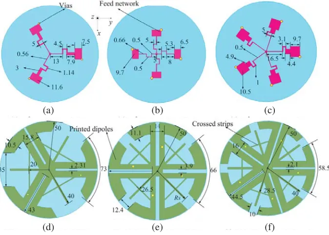
Figure 1 shows three proposed omnidirectional antennas consisting of printed dipoles, wideband power divider and crossed strips. All parts are constructed from copper and then fixed on 2 mm-thick FR4 substrates. The relative permittivity of the substrate is 4.4. The dipoles and crossed strips are etched on the bottom side of the substrate and the matching network on its top side. The proposed antennas are fed through 50 Ω RG086 coaxial cables at bottom center of the antennas. The printed dipole length of Antenna I is 0.5λ01(λ01is wavelength at 2 GHz in free space), with the increase of the printed dipole
number, the printed dipole length decrease. The dipole lengths for are 0.44λ01 Antenna II and 0.39λ01
for Antenna III, respectively. This is due to the effect of the mutual coupling between the adjacent dipoles. Compared with the existing HP antennas in [1–4, 7], the feeding networks of the proposed
(a) (b) (c)
(d) (e) (f)
Figure 1. Geometry and dimensions of the proposed antennas. (a) Top view of Antenna I, (b) top view of Antenna II, (c) top view of Antenna III, (d) bottom view of Antenna I, (e) bottom view of Antenna II , (f) bottom view of Antenna II (Unit: mm).
antennas are very simple and easy to be optimized to match with printed dipoles, as shown in Figure 1. The feeding network consists of a four-way power divider and four wideband baluns. The baluns were proposed and discussed in [8, 9]. By optimizing the dimensions of these three antennas and their feed networks, good impedance matchings are obtained, the detailed dimensions of the proposed antennas are shown in Figure 1. Their bandwidths are wide enough to cover the frequency band from 1.7 GHz to 2.7 GHz with reflection coefficients less than −15 dB, as shown in Figure 2.
2.2. Antenna Discussions
As discussed in the introduction, uniform omnidirectional radiation patterns can be obtained through uniform flowing currents along a circle. Figure 3 shows the current distributions of the three proposed antennas. With the increase of the dipole number, the current distributions become more uniform, which will lead to more uniform radiation patterns fromθ= 60◦ to θ= 90◦ conical cuts.
Figure 4 gives the normalized gains of the three proposed antennas at 2.7 GHz. The ripple of Antenna I is greater than 5 dB in the horizontal plane. With the increase of dipole number, the omnidirectional performance is improved. From Figure 4, it can be seen that the ripples are less than 1.3 dB for Antenna II and 0.8 dB for Antenna III, respectively. With the decrease of radiation ripples in the horizontal plane, the realized gains will get lower. We can choose the proper antenna (with three, four or five printed dipoles) according to practical system requirements.
The isolation will get better once a HP antenna with lower cross-polarization levels is combined with a VP antenna. Thus, a HP antenna with good cross-polarization levels leads to high quality wireless communications. HP antennas in [1–4, 7] demonstrate good omnidirectional radiation patterns and low cross-polarization levels in θ= 90◦ plane. However, for practical applications, these characteristics in
(a) (b) (c)
Figure 3. Current distributions of the proposed antennas (2.7 GHz). (a) Antenna I, (b) Antenna II, (c) Antenna III.
θ = 60◦ conical cut should also be taken into consideration. In this paper, in order to improve the cross-polarization performance inθ= 60◦ conical cut, straight and crossed strips structures are added between two adjacent printed dipoles, as shown in Figures 5(b) and (c).
Tables 1–3 show the effects of the straight and crossed strips on the cross-polarization levels of the three proposed antennas. For Antennas I, II and III without any strips, the cross-polarization levels in θ= 60◦ conical cut will increase in the higher frequency band. Once the straight strips are added, the cross-polarization levels will decrease in the higher frequency band, but they are still higher than
−15 dB at 2.7 GHz. In order to further decrease the cross-polarization levels at 2.7 GHz, crossed strips are applied. Due to effects of the crossed strips, the cross-polarization levels inθ= 60◦ conical cut are lower than −15.6 dB. Tables 1–3 also show that both straight and crossed strips have little effects on cross-polarization levels inθ= 90◦ plane. According to antenna theory, the unbalanced common mode currents flowing along two sides of the slot line will generate θ-direction components in the far-field
(a) (b) (c)
Figure 5. Antennas with different parasitic strips. (a) Without strips, (b) with straight strips, and (c) with crossed strips.
Table 1. Effects of straight and crossed strips on cross-polarization levels of Antenna I (Unit: dB).
Fre (GHz)
No Strips (θ= 60◦)
Straight Strips (θ= 60◦)
Crossed Strips (θ= 60◦)
No Strips (θ= 90◦)
Straight Strips (θ= 90◦)
Crossed Strips (θ= 90◦)
1.7 −16.5 −18.0 −19.7 −29.1 −29.2 −29.4
1.9 −16.0 −18.5 −18.9 −28.4 −28.9 −28.7
2.1 −13.9 −19.3 −18.9 −27.1 −28.1 −27.8
2.3 −10.4 −18.1 −18.6 −27.0 −25.4 −25.6
2.5 −10.7 −16.1 −16.9 −23.7 −23.1 −23.1
2.7 −9.1 −13.6 −15.6 −22.3 −21.7 −21.3
Table 2. Effects of straight and crossed strips on cross-polarization levels of Antenna II (Unit: dB).
Fre (GHz)
No Strips (θ= 60◦)
Straight Strips (θ= 60◦)
Crossed Strips (θ= 60◦)
No Strips (θ= 90◦)
Straight Strips (θ= 90◦)
Crossed Strips (θ= 90◦)
1.7 −21.3 −24.4 −22.9 −27.1 −28.1 −28.2
1.9 −19.1 −26.2 23.9 −27.2 −28.3 −29.5
2.1 −15.7 23.9 −29.8 −26.9 −28.3 −29.1
2.3 −7.2 −19.6 −24.7 −23.9 −26.3 −27.1
2.5 −9.3 −15.1 −20 −24.5 −23.3 −24.1
Table 3. Effects of straight and crossed strips on cross-polarization levels of Antenna III (Unit: dB).
Fre (GHz)
No Strips (θ= 60◦)
Straight Strips (θ= 60◦)
Crossed Strips (θ= 60◦)
No Strips (θ= 90◦)
Straight Strips (θ= 90◦)
Crossed Strips (θ= 90◦)
1.7 −25.8 −22.9 −25.9 −29.1 −28.8 −28.7
1.9 −25.3 −32.8 −24.1 28.2 −28.3 −28.1
2.1 −23.9 −27.2 −21.7 −27.4 −28.1 −29.6
2.3 −18.9 −20.6 −27.8 −25.6 −25.8 −26.6
2.5 −13.4 −16.8 −21.5 −23.0 −23.2 −23.7
2.7 −10.4 −13.1 −17.6 −20.8 −21.1 −21.5
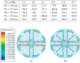
Table 4. Effects of parameter Rson cross-polarization levels of Antenna II (Unit: dB).
Fre (GHz) 1.7 1.9 2.1 2.3 2.5 2.7
Rs= 18 mm −26.5 −22.5 −17.1 −7.7 −9.5 −13.6
Rs= 21 mm −26.8 −23.3 −18.8 −12.4 −13.9 −17.3
Rs= 24 mm −26.6 −231 −17.5 −14.3 −22.4 −24.0
Rs= 27 mm −25.9 −19.9 −16.4 −29.8 −25.8 −23.6
Rs= 30 mm −24.1 −32.2 −28.9 −24.4 −20.9 −18.6
(a) (b)
Figure 6. Current distributions of Antenna II. (a) Without crossed strips, and (b) with crossed strips. (2.3 GHz).
3. SIMULATED AND MEASURED RESULTS
The proposed antennas are simulated, fabricated and measured in this paper. Figure 7 shows photographs of the three antennas. The proposed antennas are simulated by ANSYS HFSS 15 and measured by using Agilent Network Analyzer E5071C. The radiation patterns are measured by a far-field antenna measurement system.
Figure 7. Photographs of the proposed antennas.
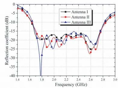
Figure 8. Measured reflection coefficients of the proposed antennas.
3.1. Reflection Coefficients
Figure 8 shows the measured reflection coefficients of the three proposed antennas. The measured results demonstrate that all proposed antennas cover the frequency band from 1.7 GHz to 2.7 GHz with reflection coefficients less than −15 dB, which show good agreement with the simulated results. The frequency band includes the DCS1800, WiFi2400 and 4G-LTE bands.
3.2. Radiation Patterns
In this paper, the radiation patterns at 1.7 GHz, 2.2 GHz and 2.7 GHz of Antenna II are simulated and measured, as shown in Figure 9. Figures 9(a)–(c) show radiation patterns in the vertical cut plane, and Figures 9(d)–(f) show the radiation patterns in θ= 60◦ conical cut. Both simulated and measured ripples are less than 1.3 dB in the whole frequency band, and the cross-polarization levels are less than
−16 dB. Figure 9 indicates that Antenna II maintains stable radiation patterns in the whole frequency band. The proposed antennas can be widely used for indoor DAS and base station systems due to their wideband performance.
(a) (b) (c)
(d) (e) (f)
Figure 9. Simulated and measured radiation patterns for Antenna II. (a) Vertical cut plane at 1.7 GHz, (b) vertical cut plane at 2.2 GHz, (c) vertical cut plane at 2.7 GHz, (d)θ= 60◦ conical cut at 1.7 GHz, (e)θ= 60◦ conical cut at 2.2 GHz, (f) θ= 60◦ conical cut at 2.7 GHz.
Figure 10. Measured gains of the proposed antennas.
4. CONCLUSION
In this paper, three horizontally-polarized omnidirectional antennas are introduced, simulated, fabricated and measured. Their bandwidths are wide enough to cover the DCS1800, WiFi2400 and 4G-LTE bands. With the increase of dipole numbers in HP antennas, the omnidirectional performance can be improved. Straight and crossed strips added between two adjacent printed dipoles improve the cross-polarization performance of the three proposed HP antennas. Their cross-polarization levels in
REFERENCES
1. Yu, Y., H. Zhang, and Z. Chen, “A broadband dual-polarized omnidirectional MIMO antenna for 4G LTE applications,”Progress In Electromagnetics Research Letters, Vol. 57, 91–96, 2015. 2. Quan, X. and R. L. Li, “A broadband dual-polarized omnidirectional antenna for base stations,”
IEEE Transactions on Antennas Propagation, Vol. 61, No. 2, 943–947, Feb. 2013.
3. Huang, H., Y. Liu, and S. Gong, “Broadband omnidirectional dual-polarized antenna with high isolation,” Microwave and Optical Technology Letters, Vol. 57, No. 8, 1848–1852, Aug. 2015. 4. Dai, X.-W., Z.-Y. Wang, C.-H. Liang, X. Chen, and L.-T. Wang, “Multiband and dual-polarized
omnidirectional antenna for 2G/3G/LTE application,” IEEE Antennas and Wireless Propagation Letters, Vol. 12, 1492–1495, 2013.
5. Lin, C. C., L. C. Kuo, and H. R. Chuang, “A horizontally polarized omnidirectional antenna for WLAN applications,” IEEE Transactions on Antennas Propagation, Vol. 54, No. 11, 3551–3556, Nov. 2006.
6. Ahn, C. H., S. W. Oh, and K. Chang, “A dual-frequency band omnidirectional antenna polarization diversity of MIMO and wireless communication applications,” IEEE Antennas and Wireless Propagation Letters, Vol. 8, 966–970, 2009.
7. Yu, Y., F. Jolani, and Z. Chen, “A wideband omnidirectional horizontally polarized antenna for 4G LTE applications,”IEEE Antennas and Wireless Propagation Letters, Vol. 12, 686–689, 2013. 8. Yeo, J. and J.-L. Lee, “Broadband compact series-fed dipole pair antenna with simplified integrated
balun,”Microwave and Optical Technology Letters, Vol. 56, No. 8, 1731–1734, Aug. 2015.