Volume 8, No. 5, May – June 2017
International Journal of Advanced Research in Computer Science RESEARCH PAPER
Available Online at www.ijarcs.info
ISSN No. 0976-5697
Speed Dictators for Forced Speed Limit at Critical places using Low Cost RF
Transceivers with Integrated Immobilizer
Megha Soni
M.Tech Scholar (Digital Communication)
S.S College of EngineeringUdaipur (Raj) India
Piyush Sharma
Associate Professor & Head (Electrical Engineering) S.S College of Engineering
Udaipur (Raj) India
Abstract: An intention to work on the topic of this nature is emanated from the interest to explore alternative technological solution to achieve effective speed control. Objective of the study is to design and develop a new system that can effectively detect speed violations on the road and supports the driver to obey traffic rules while driving by maintaining the speed according to the speed limit prescribed. In the present day scenario traffic rules are frequently violated by the drivers and over speeding occur due to bad driving behavior. So, a driver assistance system is provided to prevent over speeding, violation of road rules and also to display alert messages. The proposed system has an alerting, recording and reporting system for over speed violation management. The proposed system automatically controls the speed of vehicles at speed restricted areas such as school and hospitals. The main reason behind developing this project is to avoid accident of vehicles at speed limit zones and also to help the passengers to cross the road safely without facing any danger from high speed vehicles. Normally, the vehicle drivers not consider the passengers who crosses road in speed limited areas and drive their vehicles at high speed. So, now accidents are increasing in these areas. The traffic police control the traffic but they are not able to avoid the accidents completely. To solve this problem we developed the proposed system, which not interrupts the vehicle drivers and controls the speed of the vehicles up to certain limit in these speed restricted zones. The LCD displays the lane speed limit. Even though the traffic police controls them we cannot achieve full response from them. Also it is not possible to monitor those areas at all time to regulate their speed. This project is very useful for the common people to walk safely in the roads of speed restricted zones¬¬ and also drivers can ride their vehicles safely.
Keywords: Intelligent Speed Adaptation (ISA), Zigbee, Cruise control system (CC),Curve Warning Systems (CWS), Geographical Information Systems (GIS), Vechicle Overspeed RF, RF Transmitter, RF receiver.
I. INTRODUCTION
Movement administration out and about has turned out to be extreme issue of today's general public due to development of the urbanization, industrialization and populace; there has been a gigantic development in the activity. With development in movement, there is event of heap of issues as well; these issues incorporate congested roads, mischances and activity administer infringement at the substantial movement signals. This thusly adversy affects the economy of the nation and also the loss of lives [1]. So issue given above will turn out to be most noticeably bad later on. Activity blockage and tidal stream administration were perceived as real issues in present day urban territories, which have caused much upsetting for the rescue vehicle. In addition street mishaps in the city have been unremitting and to bar the death toll because of the mischances is considerably more vital. Expanding the limit of the roadways is costly and, in a few zones where land is rare, is impossible. Enhancing the productivity of the present transportation framework through the execution of cutting edge advances may mitigate activity clog and lessening the vehicle crash-related casualty rate. Continuous movement reconnaissance is a standout amongst the most vital parts of this approach. Street mishaps can be anticipated by receiving measures, for example, [2] Traffic administration, enhancing nature of street framework and more secure vehicles. To Ensure decrease in mischances and to enhance street security, speed control procedures, for example, speed control in school and school zones by utilizing RF handset, programmed slowing mechanisms, Camera based recognition, RFID innovation based discovery are executed. The current systems
still doesn't ready to lessen the quantity of mishaps. Thus there is a need to actualize Intelligent Speed Adaptation (ISA) in which infringement administration gives proficient checking, enrolling and revealing arrangement of speed of the vehicle which surpasses the utmost. The driving conduct of the driver is checked in view of which punishment sums are computed. A message is sent to the remote station where a prompt move can be made. Speed confine data is sent with the assistance of Zigbee which utilizes remote method of correspondence, ends up being compelling [3].
pre-characterized speed and its later development adaptation Adaptive Cruise Control (ACC) which keeps the car at pre-characterized more secure separation from the previous vehicle. Be that as it may, these frameworks neglect to recognize the bended streets where the speed of the vehicles must be lessened to maintain a strategic distance from the mishaps. Later Curve Warning Systems (CWS) appeared to identify the bended streets by utilizing Global Positioning System (GPS) and the computerized maps gotten to from the Geographical Information Systems (GIS) to caution driver of moving toward the bended street. In any case, these maps should be refreshed consistently and are not helpful if there are eccentric street redirections or mishaps [5, 6]. Here we propose a dynamic model where the framework controls the vehicle as per the information outline that is transmitted by the RF transmitter settled to the close-by street signs. The information casing is gotten by the microcontroller in car which controls the speed of vehicle. This is a RFID-Based Intelligent vehicle speed controller framework where uninvolved RF handsets are masterminded in the street near the position of genuine movement signals. This model can likewise be better used to enhance the fuel productivity by forcing the most extreme speed restrict on the cars at which the mileage will be more [7].
National reports distributed every year by Transport Research Wing of the Ministry of Road Transport and Highways and National Crimes Records Bureau of Ministry of Home Affairs, Government of India depict national measurable patterns and standardized pointers of street mischances, wounds and fatalities. This article highlights patterns, pointers, interstate examinations and the most recent attributes of street auto collisions in India. While the official street movement casualty information might be near the real number, the harm information are gross thinks little of. According to bibliometric investigation, India contributed just 0.7 for every penny papers on street activity wounds and had short of what one article on street movement wounds per 1,000 street movement related passings. To be compelling, approaches on damage counteractive action and security must be founded on neighborhood confirmation and research. Wellbeing experts and their expert bodies crosswise over wide teaches need to take an activity for the same with dynamic duty [8].
II. LITERATURE REVIEW
Swati S Sarowar, Prof Seema M Shende, SYCET, Aurangabad India.
An intention to work on the topic of this nature is emanated from the interest to explore alternative technological solution to achieve effective speed control. Objective of the study is to design and develop a new system that can effectively detect speed violations on the road and supports the driver to obey traffic rules while driving by maintaining the speed according to the speed limit prescribed. In the present day scenario traffic rules are frequently violated by the drivers and over speeding occur due to bad driving behavior. So, a driver assistance system is provided to prevent over speeding, violation of road rules and also to display alert messages. The proposed system has an alerting, recording and reporting system for over speed violation management. The Zigbee transmitter sends the speed limit of the particular lane entered by the vehicle and also gives alerts like ―road works, ―steep slopes, ―school zone
in the form of acoustical messages and also in LCD [9]. The receiver unit placed in the vehicle receives the messages and sends to the microcontroller. When speed of the vehicle nears the speed limit it displays the warning and if exceeds the limit, the microcontroller records the violated speed and time. The LCD displays the lane speed limit and shows the number of times, speed was violated. At the same time our system will control the speed, if vehicle user does not slows down the speed to that of particular zone speed limit. System will keep on counting the no. of times speed exceeded, record of which sent to the control room. Increase in the count of violation increases the penalty amount which can be collected in toll gates located nearby. Ultimately driver’s behavior can be improved here. A GSM module sends message to the nearest traffic personnel immediately after a violation occurs. An authenticated device is also provided, which can be operated only by the traffic police in whom he can retrieve the data stored at any time [10].
V. Chandra Prasad, M. Singaram, Ece Kpr Institute of Engineering and Technology
G. Pradeepkumar Assistant Professor, Ece Nandha Engineering College
The proposed system automatically controls the speed of vehicles at speed restricted areas such as school and hospitals. The main reason behind developing this project is to avoid accident of vehicles at speed limit zones and also to help the passengers to cross the road safely without facing any danger from high speed vehicles. Normally, the vehicle drivers not consider the passengers who crosses road in speed limited areas and drive their vehicles at high speed. So, now accidents are increasing in these areas [11]. The traffic police control the traffic but they are not able to avoid the accidents completely.. To solve this problem we developed the proposed system, which not interrupts the vehicle drivers and controls the speed of the vehicles up to certain limit in these speed restricted zones. The LCD displays the lane speed limit. Even though the traffic police controls them we cannot achieve full response from them. Also it is not possible to monitor those areas at all time to regulate their speed. This project is very useful for the common people to walk safely in the roads of speed restricted zones and also drivers can ride their vehicles safely.
Manjunath Chincholi, Dr K.Chandrashekara, SJCE, Mysuru, India.
Nowadays people drive very fast, accidents occur frequently and there is loss of property and life. In order to avoid such kind of accidents, to alert the drivers and to control their vehicle speed. RF technology is being used the main objective is to design a Smart Display controller meant for vehicle‟s speed control and monitoring of zones, which can run on an embedded system. Smart Display & Control (SDC) can be custom designed to fit into a vehicle‟s dashboard, and displays information on the vehicle. The project is comprises of two separate modules: zone status transmitter unit and receiver (speed display and control) unit. Once the information is received from the zones, the vehicle‟s embedded unit automatically alerts the driver, to reduce the speed according to zones, it waits for few seconds, and otherwise vehicle‟s SDC unit automatically reduces the speed [12].
III. METHODOLOGY
rates. The subsequent system will utilize little measures of energy — singular gadgets must have a battery life of no less than two years to pass ZigBee confirmation. ZigBee is an IEEE 802.15.4-based determination for a suite of abnormal state correspondence conventions used to make individual territory systems with little, low-control computerized radios [13].
The accompanying figure portrays zigbee convention stack,which comprises of four layers viz. PHY,MAC,network and security and application layer. The initial two are shrouded in IEEE 802.15.4 WPAN standard and the later two are canvassed in records distributed by zigbee cooperation.
Application Layer:
Pl. allude our article on Basics of OSI and TCPIP to comprehend application layer when all is said in done. There are two profiles at this layer. 1. Maker particular application profile-Operate as shut frameworks and furthermore guaranteed that they can coincide with other zigbee frameworks. 2. Open application profile-for this to work interoperability between different zigbee gadgets is an absolute necessity. A solitary zigbee hub underpins up to 240 application objects called end focuses. An end point indicates particular application, for instance, 0 devoted to ZDO (Zigbee gadget question), gives control and administration charges. 6 utilized for control of light. 8 utilized for oversee warming and aerating and cooling [14].
Arrange Layer:
Specially appointed on-request Distance Vector Routing convention (AODV) is utilized at system layer. Allude zigbee AODV convention for additional.
Security Layer:
On the off chance that security is empowered C will start up utilizing a 128 piece AES encryption key. Gadgets having same security key can convey on PAN. How to get this key? 1. Pre-establishment 2. Key is gotten over the air amid joining.
Macintosh Layer
Every MAC outline comprises of three fields MAC header, MAC payload and MFR (FCS).
Every MAC edge will contain Frame control field (16 bit), which convey outline sort, tending to fields and other control banners.
This MAC control field contain outline sort field, which is the primary separating variable in distinguishing one MAC outline with the other. It is 3 bit long [15].
The MAC edges are isolated into taking after four noteworthy classes, which is utilized by zigbee gadgets to build up association with the PAN by trading framework data.
1. Reference point 2. Information 3. Affirmation 4. Macintosh summon
The ZigBee convention is intended to impart information
through threatening RF situations that are normal in business and modern applications.
ZigBee convention highlights include:
• Support for different system topologies, for example, indicate point, indicate multipoint and work systems
• Low obligation cycle – gives long battery life
• Low dormancy
• Direct Sequence Spread Spectrum (DSSS)
• Up to 65,000 hubs for each system
• 128-bit AES encryption for secure information
associations
• Collision evasion, retries and affirmations
Work Networks
A key part of the ZigBee convention is the capacity to bolster work organizing. In a work organize, hubs are interconnected with different hubs so that various pathways interface every hub. Associations between hubs are progressively refreshed and enhanced through advanced, worked in work steering table.
Work systems are decentralized in nature; every hub is fit for self-disclosure on the system. Likewise, as hubs leave the system, the work topology enables the hubs to reconfigure directing ways in light of the new system structure. The attributes of work topology and specially appointed steering give more noteworthy strength in changing conditions or disappointment at single hubs [16].
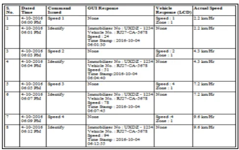
[image:3.595.314.558.514.667.2]IV. RESULTE
Table 1 Mode1: Warning Mode
achual speed is 2.2 Km/Hz. At the time 4-10-2016 and time 06:03 Pm and command Issued speed 2, Gui Response is shown in table, Vehicle Response is Speed 2 aand zone 1, achual speed is 4.3 Km/Hr. At the time 4-10-2016 and time 06:04 Pm and command Issued Identify, Gui Response is shown TABLE, Vehicle Response is NONE aand zone 1, achual speed is 4.3 Km/Hr. At the time 4-10-2016 and time 06:05 Pm and command Issued speed 3, Gui Response is shown in table, Vehicle Response is Speed 3 aand zone 1, achual speed is 7.8 Km/Hr. At the time 4-10-2016 and time 06:07 Pm and command Issued Identify, Gui Response is shown TABLE, Vehicle Response is NONE and zone 1, achual speed is 7.8 Km/Hr. At the time 4-10-2016 and time 06:09 Pm and command Issued speed 4, Gui Response is shown in table, Vehicle Response is Speed 4 aand zone 1, achual speed is 9.6 Km/Hr. At the time 4-10-2016 and time 06:12 Pm and command Issued Identify, Gui Response is shown TABLE, Vehicle Response is NONE, achual speed is 9.6 Km/Hr.
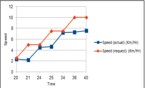
[image:4.595.309.555.246.395.2]Time vs. Speed Graph (Actual and Request)
Table 2 Mode1: Resticted Mode
At the time 4-10-2016 and time 06:20 Pm and command Issued speed 1, Gui Response is None, Vehicle Response is
Speed 1 aand zone 1, achual speed is 2.3 Km/Hr. At the time 4-10-2016 and time 06:21 Pm and command Issued Identify, Gui Response is shown TABLE, Vehicle Response is NONE aand zone 1, achual speed is 2.3 Km/Hr. At the time 4-10-2016 and time 06:24 Pm and command Issued speed 2, Gui Response is shown in table, Vehicle Response is Speed 1 aand zone 1, achual speed is 2.3 Km/Hr. At the time 4-10-2016 and time 06:25 Pm and command Issued is zone 2, Gui Response is shown TABLE, Vehicle Response is speed 2 and zone 2, achual speed is 2.3 Km/Hr. At the time 4-10-2016 and time 06:27 Pm and command Issued speed 2, Gui Response is shown in table, Vehicle Response is None, achual speed is 4.4 Km/Hr. At the time 4-10-2016 and time 06:29 Pm and command Issued Identify, Gui Response is shown TABLE, Vehicle Response is NONE, achual speed is 4.5 Km/Hr.
Time vs. Speed (Actual and Request)
This graph shows that relation between time and speed (Actual and Request), as shows in the figure. At the time 20 Min speed is 2.3 (Km/Hr) Actual speed and 2.5 (Km/Hr) is request speed. At the time 24 Min speed is 4.5 (Km/Hr) Actual speed and 5.0 (Km/Hr) is request speed. At the time 34 Min speed is 7.2 (Km/Hr) Actual speed and 7.5 (Km/Hr) is request speed. At the time 40 Min speed is 7.6 (Km/Hr) Actual speed and 10.0 (Km/Hr) is request speed.
V. CONCLUSION AND FUTURE SCOPE
Conclusion
The author has presented a prototype design of a system that can enhance road safety significantly by controling speed limit of vehicles via secure zigbee protocol. The proposed system is simple & durable & offer low cost implementation. As zigbee molules are used, the system consum very less power. The described system is easy to implement on a present system which ensure maximum safety for drivers, passengers & pedestrains. The driver gets all the information on a LCD, for distraction free operation. Driving safety is highly enhanced, which offers a positive cost differential to the government.
Future Scope
determination of vehicle location & speed for stricter low enforcement. Also there is scope for utility pole mounted transcievers connected to each other & then to Intanct for truly remoteused based control & Monitorning.
VI. REFERENCES
[1]. Rajat & Nirbhay Kumar ― RFID Resolution: Your cars will be tagged‖, The Economics Times, 25 September 2007.
[2]. K.Athavan; S.Jagadeeshwaran ―Ambulance Rescue system‖, International Journal of Advanced Technology & Engineering Research (IJATER), ISSN NO: 2250-3536, VOLUME 2, ISSUE 2, and MAY 2012.
[3]. Masoud Hamedi and Ali Haghani,‖ Traffic Data Collection And Anonymous Vehicle Detection Using Wireless Sensor Networks‖, May 2012
[4]. Rubini.R and Uma Makeswari.A, ―Over Speed Violation Management Of A Vehicle Through Zigbee‖,pp. 340-344, Vol 5 No 1 Feb-Mar 2013
[5]. Wang Wei, Fan Hanbo, ―Traffic Accident Automatic Detection and Remote Alarm Device‖, ISSN -978-1-4244-8039-5, IEEE 2011.
[6]. Rajesh Kannan Mega lingam, Ramesh Nammily Nair, Sai Manoj Prakhya, Amrita Vishwa Vidyapeetham, Amritapuri, Clappana, ―Wireless Vehicular Accident Detection and Reporting System‖, IEEE 2010.
[7]. Kumar Chaturvedula, ―RFID Based Embedded System for Vehicle Tracking and Prevention of Road Accidents‖, IJERT, Vol. 1, Issue 6, August – 2012.
[8]. Lujaina AI –Shabibi, Nadarajan Jayaraman, Jayavrinda Vrindavanam,‖Automobile Speed Violation Detection
System Using GSM and RFID Technologies‖
International Journal of Applied Information System, ISSN-2249-0868Volume 7, and pp: 24-29, July 2014.
[9]. http://www.nhtsa.gov/people/injury/research/pub/hs80901 2.html
[10]. Vladimir Glavtchev, Pınar Muyan-Ozcelik, Jeffrey M. Ota, and John D. Owens, ― Feature-Based Speed Limit Sign Detection Using a Graphics Processing Unit‖, IEEE Intelligent Vehicles Symposium, pp: 195 - 200, 2011.
[11]. Helia Mamdouhi, Sabira Khatun and Javad Zarrin, ―Bluetooth Wireless Monitoring, Managing and Control for Inter Vehicle in Vehicular Ad-Hoc Networks‖, Journal of Computer Science, Science Publications, 2009.
[12]. Abdul-Wahid A.Saif, Haytham Sammak,‖Au tomatic Monitoring and Speed Violation Ticket System‖, ISSN -978-14244-6588-0/10,pp-1068-1075, IEEE 2010
[13]. A design model for Automatic vehicle speed Control, International Journal for Computer Applications, volume-35, No.9, December 2011.
[14]. Design and Prototype of an In-Vehicle Road Sign Delivery System using RFID, 2012 12th International Conference on ITS elecommunications.
[15]. Design of RF based Speed control system for
vehicles, International Journal of Advanced Research in Computer and Communication Engineering Vol. 1, Issue 8, October 2012.
[16]. Vehicle Speed Control using R.F. Technology,