Volume 5, No. 3, March-April 2014
International Journal of Advanced Research in Computer Science
RESEARCH PAPER
Available Online at www.ijarcs.info
Energy Efficiency in WSN by implementing LEACH and PEGASIS
Bhagwant Singh*
CSE Department
Ramgarhia Institute of Engg & Tech Phagwara, India
Kumar Saurabh
Assistant Professor, IT Department Ramgarhia Institite of Engg. &Tech.
Phagwara, India
Barjinder Singh
Assistant Professor, CSE Department Lovely Professional University Phagwara, India
Abstract: Since wireless sensor nodes have limited energy resource that cannot be recharged and are randomly scattered in the observation fields, energy efficiency becomes one of the most important problems. We begin our study with a review of basic terminology and protocols that are energy efficient as well as some proposed methods of improvement and performance. Following this we will review which aspects of these protocols can be further modified to improve performance and by their simulation results prove or disprove that there is cause to further research the proposed method of modifying the energy efficient algorithms. Some of the proposed algorithms include: LEACH, BCDCP, PEGASIS. We move our study from introduction of how network topology impacts performance to how the algorithms perform on the network to how introducing changes in the network topology and accommodating those changes with the algorithm affect performance. With these changes in mind, concluding we will propose research on another energy efficient algorithm which is enhanced LEACH with better QoS on the basis of best path selection and compared with PEGASIS.
Keywords:-Sensors, Zones, cluster, LEACH, PEGASIS
I. INTRODUCTION
A wireless sensor network (WSN) is a collection of sensor nodes distributed over a particular area to monitor back to a base station (BS). An application for a wireless sensor network can be in both civil and military; for example, battlefield surveillance. Sensor node has a limited battery power and capability. Power consumption has been one of the important factors in mobile wireless network. To make a wireless network operate autonomously, each node in the network must be able to provide adequate communication while consuming as minimum power as possible. There have been many research papers in this field that address such an issue and propose their own algorithm to efficiently minimize the power consumption and effectively maximize the lifespan of the network. In this paper, some classic protocols are compared and discussed. We start from the conventional protocols such as direct transmission protocol that sensor node sends data directly to a distant base station and consumes its energy rapidly. That leads to Minimum-transmission-energy (MTE) routing protocol that reduces distance for transmitting packet to BS by routing a data packet through multiple intermediate nodes. Following this, we briefly introduce classical energy-efficient algorithm, which is enhanced LEACH (Low-Energy Adaptive Clustering Hierarchy) with better QoS on the basis of best path selection and compared with PEGASIS (Power-Efficient Gathering in Sensor Information Systems).
LEACH introduces clustering based protocol, where sensor nodes are grouped in several clusters and have randomized rotation of cluster-heads that will transmit a data to BS. PEGASIS is a chain-based protocol built on top of idea from LEACH, which nodes communicate only to its
neighbor and takes turn to be leader to send data back to the BS.
II. PROPOSED SCHEMES
To further improve energy efficiently, two approaches introduced in the papers are summarized in the following that leads us to start thinking about constructing the networks.
A. LEACH (Low-Energy Adaptive Clustering Hierarchy):
LEACH is a cluster-based wireless sensor networking protocol. LEACH adapts the clustering concept to distribute the energy among the sensor nodes in the network. LEACH improves the energy-efficiency of wireless sensor networking beyond the normal clustering architecture. As a result, we can extend the life time of our network, and this is the very important issue that is considered in the wireless sensor networking field. In LEACH protocol, wireless sensor networking nodes divide themselves to be many local clusters. In each local cluster, there is one node that acts as the base station (or we can call it “cluster-head”). Hence, every node in that local cluster will send the data to the cluster-head in each local cluster. The important technique that makes LEACH be different from the normal cluster architecture (drain the nodes battery very quickly) is that LEACH uses the randomize technique to select the head depending on the energy left of the node. After cluster-head is selected with some probability, the cluster-cluster-heads in each local cluster will broadcast their status to the sensor nodes in their local range.
cluster-head will make a schedule for the nodes in its cluster. For more efficiency, each sensor node could turn-off waiting for their allocated transmission. Cluster-heads will collect the data from the nodes in its cluster, and compresses that data before transmitting to the base station. By following this protocol, the base station will get the data from all sensor nodes that we are interested, and ready for the end-user to access the data.
In leach protocol there are number of rounds for performing the operation. In each round the different cluster heads are chosen for collecting the data of within a cluster from other nodes then cluster head transmit the data to the sink node. Node which becomes a cluster head once cannot become the cluster head for the next p rounds. It means each node has a 1/p probability to become cluster head in each round.
After a one round completion each node that is not a cluster head selects the closest cluster head and joins that cluster to transmit data. Then all the cluster heads aggregate the data and transmit it to the sink or base station. This phenomena increase the lifetime of large number of nodes.
There are two phases in LEACH protocol: a. Setup phase
b. steady-state phase.
In the setup phase the clusters are formed and the cluster-heads are selected. In the steady-state phase, the data from non cluster heads are transmitted to the sink. The sensor nodes communicate to the cluster-heads using TDMA schedule. The nodes communicate to the cluster-head only in their allotted slots. It avoids collision. The cluster-heads are selected randomly for every round.
LEACH is an efficient and self-organised algorithm. However, it suffers from some problems. First, assuming a bandwidth of l Mbps, the authors of LEACH used 50 nJ/bit for Eelec and 100 pJ/bit/m2 for Eamp. Thus will he reduced to
r2n < 1000. If 10 ft<r < 30 ft (3 and 9.1 m), we will have 12 <n < 111. Therefore, n cannot exceed 111 nodes in the best case for the given parameters. For networks bigger than 111 nodes, the direct communication may not be preferred to hop-by-hop routing, whereas it is typical for a sensor network to have hundreds of nodes. Second, LEACH results in a long latency for the BS to receive the sensed data. Moreover, the larger the sensor network is, the longer the latency will be. Finally, the number of clusters may not be fixed every round. At each round, a node n selects a random number k between 0 and 1. If this number is less that a threshold T(n) defined as, the node becomes a cluster head.
T(n)={p/1-p*[r mod(1/p)]}
Where P is the desired percentage of cluster-heads, r is the current round, and G is the set of nodes that have not been cluster heads in the last 1/P rounds. Due to the selection of k, number of cluster heads may not be fixed.
B. PEGASIS (Power-Efficient Gathering in Sensor Information Systems):
This is improved version from LEACH. Although LEACH balances the energy cost, by clustering, sensor still needs relative large energy to transmit data to its cluster head. The main idea of PEGASIS is that nodes are formed into a chain where each node receive from and transmit to closest neighbor only. The distance between sender and receiver is reduced as well as decreasing the amount of transmission.
III. RESEARCH METHODOLOGY
Figure: 1
IV. COMPARISON OF PEGASIS AND LEACH PROTOCOLS
The next review is of the effectiveness of using graph theory tree traversal algorithms to generate the chain of sensor nodes in the classical Power Efficient-Gathering in Sensor Information Systems (PEGASIS) data aggregation protocol for wireless sensor networks. PEGASIS first constructs an undirected minimum-weight spanning tree (ud-MST) on a complete sensor network graph, and uses the Euclidean distance between the constituent nodes of the edge as the weight. A Breadth-First-Search of the ud-MST, starting with the node located closest to the center of the network, is then conducted to construct a rooted directed minimum-weight spanning tree (rd-MST). The three tree traversal algorithms are then executed on the rd-MST and the node sequence resulting from each of the traversals is used as the chain of nodes for the PEGASIS protocol.
node is randomly selected. The leader node is responsible for forwarding the aggregated data to the sink. Once the leader node is selected and notified by the sink node, each node in both sides of the chain (with respect to the leader node), receives and transmits the aggregated data to the next node in the chain, until the data reaches the leader node.
V. SIMULATION RESULTS
[image:3.595.315.565.92.358.2]In this section, we evaluate the performance of our proposed protocol using MATLAB. We consider a wireless sensor network with 100 nodes randomly distributed in a 100m × 100m field. The BS is fixed and located at the position (50, 175), which is far away from the field. All sensor nodes in the network are homogeneous and are sensing at the same rate constantly.
Figure 1: Deployment of sensor nodes with cluster heads
The first scenario show the scenario of LEACH protocol that how clustering occur. We take a dynamic environment in which every time nodes come at different position. Clustering of data is also random. As we know that due to Clustering, nodes are dead after some time, graph shows that how active nodes are become dead with respect to time.
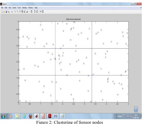
Figure 2: Clustering of Sensor nodes
The above figure shows the initial sensor placement. After the deployment of sensor nodes, clustering is done in
which the wireless sensor network is divided into various clusters. Here the deployment area is divided into nine clusters.
Figure3: Cluster Heads integrated with sensor nodes.
In the next phase, the most approachable node is selected as the cluster head. The various clusters are separated with different colors in the simulation. The full dark nodes represent the cluster heads.
Figure4: Connecting all the sensors in a zone to its cluster head.
[image:3.595.35.285.534.752.2]Figure5: Connectivity of cluster heads with each other and to the Base Station.
After the connectivity of sensors to their cluster heads, all the cluster heads connect with each other and also to the base station. All the information collected by the sensors forwarded to the base station via the cluster heads. This is the case of LEACH Protocol.
Figure 6: Connectivity of cluster heads to Base Station using PEGASIS Protocol.
In case of PEGASIS, all the cluster heads connect with each other using a single path and then to the base station through the same path. Due to this, it is more energy efficient.
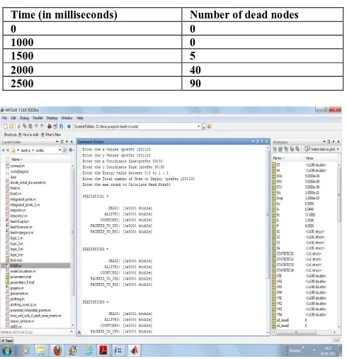
Figure7: Implementation result of PEGASIS, Shows how nodes are becoming dead.
[image:4.595.315.560.93.346.2]The above graph shows the number of dead nodes with respect to time in case of PEGASIS simulation.
Table I: Table showing dead nodes w.r.t time.
Time (in milliseconds) Number of dead nodes
0 0
1000 0
1500 5
2000 40
2500 90
Figure8: Parameters pass to the simulation to compare LEACH and PEGASIS energy efficiency.
The various parameters are passed in terms of x and y coordinate, total number of nodes deployed, energy value and maximum rounds to calculate dead nodes. The generated results shown in the next scenario.
[image:4.595.321.553.653.759.2]Figure9: Comparison of LEACH and PEGASIS protocols.
Table 2: Comparison of dead nodes in LEACH and PEGASIS w.r.t time.
Time No. of dead nodes in
LEACH
No. of dead nodes in PEGASIS
0 0 0
1000 1 0
1500 40 5
2000 80 40
The above table describes the number of dead nodes with respect to time for LEACH and PEGASIS protocols. From the above results, we conclude that the number of dead nodes in LEACH protocol is almost double than that of PEGASIS protocol.
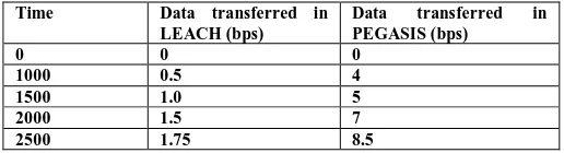
Table 3: Comparison of data transferred in LEACH and PEGASIS in a given time.
Time Data transferred in
LEACH (bps)
Data transferred in PEGASIS (bps)
0 0 0
1000 0.5 4
1500 1.0 5
2000 1.5 7
2500 1.75 8.5
The above table describe the data transfer comparison in bps with respect to time for LEACH and PEGASIS protocols. From the above results, we conclude that the throughput of PEGASIS protocol is nearly double than that of LEACH protocol.
VI. CONCLUSION
Routing in sensor networks is a new area of research, with a limited but rapidly growing set of results. In this article, there is a comprehensive survey of routing techniques in wireless sensor networks using LEACH and PEGASIS protocols. They have the common objective of trying to extend the lifetime of sensor network while not compromising data delivery. This will reduce the overhead and improve lifetime of the network.
PEGASIS, a greedy chain protocol that is near optimal for a data-gathering problem in sensor networks. PEGASIS outperforms LEACH by eliminating the overhead of dynamic cluster formation, minimising the distance non leader-nodes must transmit, limiting the number of transmissions and receives among all nodes, and using only one transmission to the BS per round.
VII. FUTURE SCOPE OF WORK
Concept of Chain formation from PEAGSIS protocol and concept of residual energy and certainty of CHs formation of LEACH protocol are used in implementation to enhance energy efficiency of sensor nodes.
In future we can introduce heterogeneity in terms of energy in which some percentage of the nodes will have more energy than other nodes using both the protocols. We can enhance the performance of the network by increasing the energy of some nodes in the network which will help to increase the lifetime of the network. Although we compared enhanced LEACH with PEGASIS, still there are many protocols that have to be compared. We should consider more factors that can affect the lifetime of WSN.
VIII. REFERENCES
[1]. Ahmed A. Ahmed, Hongchi Shi, and Yi Shang, “A Survey On Network Protocols For Wireless Sensor Networks”, Department of Computer Engineering & Computer Science, pp. 301 - 305, Aug. 2003.
[2]. Fan Xiangning, Song Yulin, “Improvement on LEACH Protocol of Wireless Sensor Network”, IEEE, pp. 260-264, 2007.
[3]. FengSen, Qi Bing, Tang Liangrui, “An Improved Energy-Efficient PEGASIS-Based Protocol in Wireless Sensor Networks”, IEEE, 2230 - 2233 , 2011.
[4]. Ian F. Akyildiz, Weilian Su, Yogesh Sankara subramaniam, and ErdalCayirci, “A Survey on Sensor Networks” , IEEE , August 2002.
[5]. Jason Lester Hill,“System Architecture for Wireless Sensor Networks”, 2003.
[6]. LaialiAlmazaydeh, EmanAbdelfattah, Manal Al- Bzoor, and Amer Al- Rahayfeh, “Performance Evaluation of Routing Protocols In Wireless Sensor Networks”, pp. 273-279, April 2010.
[7]. Stephanie Lmdsey and CauligiS. Raghavendra, “PEGASIS: Power-Efficient Gathering in Sensor Information Systems”, IEEE, pp.1125-1130, May 2002.
[8]. Nagarajan. M and S. Karthikeyan “ A New Approach to Increase the Life Time and Efficiency of Wireless Sensor Network” ,pp. 1909 – 1912, 2011.
[9]. Hwa Young Lim, et al. Sung Soo Kim, Hyun Jun Yeo, Seung Woon Kim, and Kwang Seon Ahn, “Maximum Energy Routing Protocol based on Strong Head in Wireless Sensor Networks”
[10]. Chi-Tsun Cheng, Chi K. Tse and Francis C. M. Lau, “A Delay-Aware Data Collection Network Structure for Wireless Sensor Networks” , IEEE ,2011.
[11]. Laiali Almazaydeh, Eman Ebdelfattah, Manal Al- Bzoor, and Amer Al, “Performance Evaluation of Routing Protocols in Wireless Sensor Networks” , pp. 3032-3080, vol. 55, no. 13, 2011
[12]. Jia Xu,Ning Jin, Xizhong Lou,Ting Peng,Qian Zhou,Yanmin Chen, “Improvement of LEACH protocol for WSN”, IEEE ,2012
[13]. Leandro A. Villas, Daniel Guidoni, Azzedine Boukerche, Regina B. Araujo, and Antonio A. F. Loureiro, “Dynamic and Scalable Routing to Perform Efficient Data Aggregation in WSNs”
[14]. Mohammad Reza Mazaheri, Behzad Homayounfar, Sayyed Majid Mazinani, “QoS Based and Energy Aware Multi-Path Hierarchical Routing Algorithm in WSNs”, November 2011.
[15]. I.F. Akyildiz, W. Su*, Y. Sankarasubramaniam, E. Cayirci, ”Wireless sensor networks: a survey” pp. 393-422, March 2002.