Volume 3, No. 3, May-June 2012
International Journal of Advanced Research in Computer Science
RESEARCH PAPER
Available Online at www.ijarcs.info
ISSN No. 0976-5697
Design and Analysis of Software Architecture with Unified Modeling Language
Kamna Gauri* and Dipanwita Thakur Dept.of Computer Science & Electronics
AIM & ACT Banasthali University Tonk (Rajasthan), India
Abstract: Software Architecture is being widely used today to describe a very high level design methodology of large & heterogeneous software systems. A good Architectural representation scheme holds the key to the effectiveness of a Software architecture description and usage. In this paper, we look at UML (unified modeling language) as a prospect for a generalized architecture description language. UML also “unifies" the design principles of each of the object oriented methodologies into a single, standard, language that can be easily applied across the board for all object-oriented systems and a scheme AND-OR DFD method is introduced and developed.
Keywords: Software Architecture, Unified Modeling Language, Software Architectural modeling view
I. INTRODUCTION
An Architectural Style defines a family of systems in terms of a pattern of structural organization. An awareness of these Architectural styles can simplify the problem of defining system architectures. However, most large systems are heterogeneous and do not follow a single architectural style. Software Architecture determines how system components are identified and allocated, how the components interact to form a system, the amount and granularity of communication needed for interaction, and the interface protocols used for communication among stakeholders:Customers, managers, designers, programmers. Software Architecture consists of components, connectors, data, a configuration, and a set of architectural properties.
An important feature of architecture is the ability to facilitate development of large systems, with components and connectors of varying granularity, implemented by different developers, in different programming languages, and with varying operating system requirements. [1]
a. Component: A component is an abstract unit of
software that provides a transformation of data via its interface. Components can be computation units or data stores. According to [2], components are loci of computation and state.
b. Connector: A connector is an abstract mechanism that
mediates communication, coordination, or cooperation among components. The connectors play a fundamental role in distinguishing one architectural style from another and have an important effect on the characteristics of a particular style [3].
c. Datum: A datum is an element of information that is
transferred from a component, or received by a component, via a connector.
d. Configuration: A configuration is the structure of
architectural relationships among components, connectors, and data during some period of system run-time.
II. INTRODUCTION TO UML
a. UML (Unified modeling language) is a clear and concise modeling language without being tied down to any technologies. It provides the ability to capture the
characteristics of a system by using notations and is the language that can be used to model systems and make them readable.
b. UML is a language to specify, to visualize and to build and to document the artifact of the software systems, as well as to model business and other systems besides software systems. [4]
c. UML provides a wide array of simple, easy to understand notations for documenting systems based on the object-oriented design principles. These notations are called the nine diagrams of UML.
III. INTRODUCTION TO UML DIAGRAMS
UML is made up of nine diagrams that can be used to model a system at different points of time in the software life cycle of a system.
The nine UML diagrams are:-
A. Use case Diagram:
This diagram is used to identify the primary elements and processes that from the system. The primary elements are termed as "actors" and the processes are called "use cases."
B. Class Diagram:
This diagram is used to refine the use case diagram and define the detailed design of the system. The class diagram classifies the actors defined in the use case diagram into a set of interrelated classes. The relationship or association between the classes can be either an "is-a" or "has-a" relationship. Each class in the class diagram may be capable of providing certain functionalities.
C. Object Diagram:
D. State Diagram:
Objects in the system change states in response to events. In addition to this, a state diagram also captures the transition of the object's state from an initial state to a final state in response to events affecting the system.
E. Activity Diagram:
This diagram is used to capture the process flows in the system. Similar to a state diagram, an activity diagram also consists of activities, actions, transitions, initial and final states, and guard conditions.
F. Sequence Diagram:
A sequence diagram represents the interaction between different objects in the system. This means that the exact sequence of the interactions between the objects is represented step by step. Different objects in the sequence diagram interact with each other by passing "messages".
G. Collaboration Diagram:
A collaboration diagram groups together the interactions between different objects. This diagram helps to identify all the possible interactions that each object has with other objects.
H. Component Diagram:
The component diagram represents the high-level parts that make up the system. This diagram depicts, at a high level, what components form part of the system and how they are interrelated. It also depicts the components culled after the system has undergone the development or construction phase.
I. Deployment Diagram:
The deployment diagram captures the configuration of the runtime elements of the application. This diagram is by far most useful when a system is built and ready to be deployed.
IV. INTRODUCTION TO ARCHITECTURAL
MODELING VIEWS
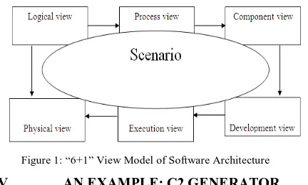
To describe Software Architecture, we use a model composed of multiple views or perspectives. In order to eventually address large and challenging architectures, the model we propose is made up of six main views:
a. Logical view, which is the object model of the design(when an object-oriented design method is used) b. Process view, this view deals with concurrency and
distribution, system integrity, and fault tolerance [5]. c. Component view, which shows the grouped modules
of a given system, modeled using the component diagram.
d. Development view, which describes the static organization of the software in its development environment.
e. Physical view, which describes the mapping(s) of the software onto the hardware and reflects its distributed aspect
f. Execution view, which is the runtime view of the system. It involves the mappings of modules to run-time images, defining the communication among them, and assigning them to physical resources. Resource
[image:2.595.335.551.83.213.2]usage and performance are key concerns in the execution view.
Figure 1: “6+1” View Model of Software Architecture
V. AN EXAMPLE: C2 GENERATOR
Let us consider a software system called C2 Generator. This software system would be written in an object oriented language like JAVA and it attempts to generate an architectural representation diagram based on the C2 Generator architecture. [6]
It takes as input the components of the system to be modeled, the connectors and a list of who notifies whom. But it will suffice to say here that C2 Generator is an architecture description language (ADL) that is used to model user interface intensive software systems i.e., applications that have a graphical user interface (GUI) aspect.
This architectural style consists of components and connectors. Components and connectors both have a defined top and bottom. The top of a component may be connected to the bottom of a single connector. The bottom of a component may be connected to the top of a single connector. There is no bound on the number of components or connectors that may be attached to a single connector.
In C2-style architecture, connectors transmit messages between components, while components maintain state; perform operations, and exchange messages with other components via two interfaces which are called top and bottom.
Each interface consists of a set of messages that may be sent and a set of messages that may be received. Inter-component messages are either requests for a Inter-component to perform an operation, or notifications that a given component has performed an operation or changed state.
In the C2 style, components cannot interact directly but can do so using the connectors. Each component interface can be attached to at most one connector. A connector, however, can be attached to any number of other components and connectors. Request messages can only be sent “upward” through the architecture, and notification messages can only be sent “downward.”The C2 style has another requirement that the components communicate with each other only through message passing and never through shared memory. Also, C2 requires that notifications sent from a component correspond to the operations of its internal object, rather than the needs of any components that receive those notifications.
This constraint on notifications helps to ensure substrate independence, which is the ability to reuse a C2 component in architectures with differing substrate components (e.g., different window systems).
execute in their own threads of control, the deployment of components to hosts, or the communication protocol(s) used by connectors.
There are four primary components in this software. The CreateConnection component has five subcomponents, which are the various steps taken to create a connection. First, the component to be connected to first created component is identified from the connection list. Then new ports are created and attached to both these components.
We assume here for simplicity that both components can have unlimited number of ports and so unlimited number of connections. Then the connector is created and the two ports are connected. It is obvious that the steps in creating a new connection start with reading a component name from the connection list till the connector is attached to the two newly formed ports.
[image:3.595.41.268.555.724.2]This whole process has to be repeated till there are no more entries in the connection list. This iterative property of the system cannot be known from the decomposition model, though it must occur if the system executes correctly. Second, there might be repeated entries in the connection list.
Table 1 Process Decomposition of C2 Generator
Module Name Submodule(s)
1) ReadInput 2) CreateComponent 3) ReadConnectionList
4) CreateConnection CreateComponentToBeConnected
CreatePorts
ConnectPortsToBothComponents CreateConnector
ConnectBothPortsWithConnector
There is no restriction to the number of connections one component can have with other components. For an entry that refers to a component which has already been created, one doesn’t need to create it again, but just identify that component and create a new port. Hence, once an entry has been read from the Connection List, one of two things happen depending on the read value. Either the component doesn’t exist and needs to be created, or it exists and needs to be identified. Again, there is no way of knowing this from the decomposition model. Let us now consider how the AND-OR DFD tackles these issues.
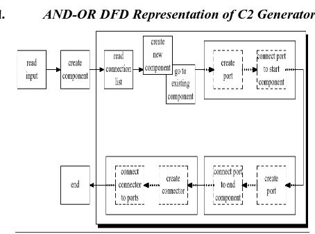
A. AND-OR DFD Representation of C2 Generator:
Figure 2 AND-OR DFD representation of C2 Generator (process view)
From Figure 2, we see that the data flow is represented by this modified DFD, but with two significant differences. Firstly, there is an OR-group of two components that
illustrate that once an entry has been read from the connection list, either a new component is created, or control moves to an existing component, depending on the value read from the connection list. Second, the iterative portion of the system has been illustrated by a shaded box. So we now can tell that the steps starting from the reading of the connection list to the connection of the ports by a connector are iterative and are executed for each entry in the connection list.
VI. UML FOR SOFTWARE ARCHITECTURE
In order to represent architecture using UML, the architecture is separated into four views: conceptual, module, execution and code. Each of these views addresses different concerns, and separation of these concerns allows the architect to make decisions without design trade-offs.
a. The conceptual view (logical view) describes the architecture in terms of domain elements.
b. The module view describes the decomposition of the software and its organization into layers. c. The execution view (process view) is the run-time
view of the system.
d. The code view captures how modules and interfaces in the module view are mapped to source files, and run-time images in the execution view are mapped to executable files.
VII. ARCHITECTING WITH UML
In order to see how UML can construct the Software Architecture of a system, let us go back to the example of the C2 Generator. Table 2 shows the logical decomposition of the system. The use of layering in modeling C2 style architecture for GUI intensive software systems [6] and the use of layering in representation of module view of an architecture using UML also indicate the vast potential for the layering style.
The logical (conceptual) decomposition highlights the main components of the system and their subcomponents if any.
Table 2: Logical Decomposition of C2 Generator
component and the connected component here) and updates the two components for the connection created.
A. Conceptual View:
[image:4.595.42.292.161.384.2]From table2, we came to know about Logical decomposition of C2 Generator. Let us now try to construct the logical architectural view for C2 Generator. Figure 2 shows the conceptual architectural view of the C2 Generator using UML constructs.
Figure 3: Conceptual view of C2 Generator
Figure 3 show the conceptual architectural view of the C2 Generator using UML constructs [7].
The problem with this representation lies in the relationship of the port and the Connector Conn. i.e. a connector can be broken off from one component and joined to another component. So a composition doesn’t hold good here. Even an aggregation doesn’t hold good because when the connector is isolated from the ports of both the connecting components, it ceases to exist independently. So here is a situation where there is a composition relationship that involves two components and a connector.
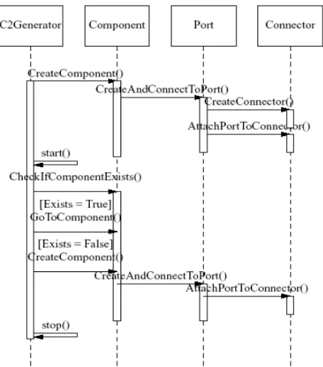
B. Execution View:
The execution view or process view of C2 Generator will be modeled from the process decomposition model we saw earlier. Figure 4 shows one sequence diagram representing the execution configuration of the C2 Generator.
The C2Generator first creates the connecting component by calling the Create Component () procedure and interacting with the component module. The component module in turn then creates a port and connects the newly
[image:4.595.322.550.198.457.2]created component to it by calling the Create And Connect To Port () procedure and communicating with the Port module. The Port module now creates the connector and attaches the port to this connector by calling two functions and talking to the Connector module. Once this is done and the control is back to the C2 Generator component, it now reads the connection list and checks if the component to be connected exists or not. If it exists, control moves to this existing component and that component is connected via a new port to the already created connector. If the component doesn’t exist then it is created before being connected to the connector.
Figure 4: Sequence Diagram for a process view of C2 Generator
This implementation is efficient because the control flow doesn’t move back and forth. Both the components are ready before the ports are created and both the ports are ready before the connector is created and the connection made. So we see that UML is rather useful for representing different views of the software architecture of a system [7, 8]. It does reasonably well and represents all the facets of that view clearly. Moreover, UML is good for all the views, and not just the process view which can be adequately represented by the AND-OR DFD. Moreover, we can extend UML by constraints, tagged values, stereotypes and profiles [9].
Table3: Summary of “6+1” view model of Software Architecture
View Components Connectors Containers Stakeholders Concerns Tool Support
Logical Class association,
inheritance, containment
Class category End-user Functionality Rose
Process Task Rendezvous,
Message, broadcast, RPC, etc.
Process System
designer, integrator
Performance, availability, S/W fault tolerance, Integrity
UNAS/SALE DADS
Development Subsystem compilation dependency, “with” clause, “include”
Subsystem (library)
Developer, manager
Organization, reuse,
portability, line of-product
Apex, SoDA
Physical Node Communication
medium, LAN, WAN, Bus, etc.
Physical subsystem
System designer
Scalability, performance, availability
UNAS, Openview DADS
Execution Mappings of node Run time view End-user,
Developer
Resource usage and performance
Rose
Scenario Step,
Scripts
Web End-user,
developer
Understandability Rose
VIII. REFERENCES
[1]. Medvidovic, N., Taylor, R.: "A framework for classifying and comparing architecture description languages," Proceedings of the 6th European conference held jointly with the 5th ACM SIGSOFT international symposium on Foundations of software engineering, Zurich, Switzerland, Pages: 60 - 76, 1997.
[2]. Shaw, M., DeLine, R., Klein, D., Ross, T., Young, D., Zelesnik, G.: "Abstractions for Software Architecture and Tools to Support Them," IEEE Transactions on Software Engineering, 21(4):314-335, April 1995.
[3]. Perry, D., Wolf, A.: "Foundations for the study of software architecture," ACMSIGSOFT SoftwareEngineering Notes, Volume 17, Issue 4 (October 1992), Pages: 40 - 52, 1992.
[4]. “OMG Unified Modeling Language Specification,” Version 1.5, March 2003.
[5]. Clements, C., Bachmann, F., Bass, L., Garlan, D., Ivers, J., Little, R., Nord, R., Stafford, J.: “Documenting Software
Architectures: Views and Beyond.” Addison- Wesley, 2003, ISBN 0-201-70372-6.
[6]. Medvidovic, N., Rosenblum, D.: "Assessing the Suitability of a Standard Design Method for Modeling Software Architectures." In Proceedings of the First Working IFIP Conference on Software Architecture (WICSA1), pages 161-182, San Antonio, TX, February 22-24, 1999.
[7]. Hofmeister, C., Nord, R., Soni, D.: “Applied Software Architecture,” Addison- Wesley, 2000, ISBN 0-201-32571-3.
[8]. Hofmeister, C., Nord, R., Soni, D.: "Describing software architecture with UML,"Proceedings of the TC2 First Working IFIP Conference on Software Architecture (WICSA1), Pages: 145 - 160, 1999.