ISSN 2286-4822 www.euacademic.org
Impact Factor: 3.4546 (UIF)
DRJI Value: 5.9 (B+)
Full Vehicle Suspension System with In-Wheel
Electric Motors
ABDUSSALAM ALI AHMED1
RAFAT S. A. ABUMANDIL
Department of Mechanical Engineering College of Engineering, Bani Waleed University, Libya
Abstract
The objective of this paper is to study the performance of a vehicle suspension system using full model and four In-wheel electric motors. The suspension system of vehicle typically evaluated by its ability to produce good passenger comfort, road handling, improve and capture the basic performances of the vehicle suspension such as the body absolute velocity, suspension travels, wheel deflection and body pitch angle. The simulation is performed based on the mathematical model of the full car suspension system by using MATLAB/SIMULINK software. It is known that theIn-Wheel motors will increase the mass of the wheel which called the unsprung mass. This paper summarized a bad effect of increasing the mass of wheels by add In-Wheel Motors to the vehicle suspension system on the vehicle drivers comfort and the road traction.
Keywords: Unsprung mass, Suspension system In-wheel motor,
Simulink model, full car model
INTRODUCTION
Traditionally the designs of vehicle suspensions have been compromise between a three conflicting criteria’s which namely passenger comfort, road handling, and load carrying. The suspension systems must support the vehicle, provide effective isolation of passengers, provide directional control using handling maneuvers and the load disturbance. Best ride comfort of passenger requires a soft suspension, while insensitivity to apply the loads requires stiff suspension. Best handling of vehicle requires a suspension setting somewhere between it. According to these conflicting demands, the design of suspension has to be something that can compromise the two problems.
Suspensions consist of the system of springs, shock absorbers, and linkages which connects the vehicle with its wheels. By other meaning, the suspension system can be defined as a mechanism which physically separates the body of car from the car wheels. The major function of the vehicle suspension system is to decrease the acceleration in the vertical direction which transmitted to the passengers that directly provides the road comfort. The main three types of the vehicle suspension system are; active, passive, and semi-active suspension systems. Traditional suspensions consist of dampers and springs which are referred to as passive suspension, if the suspension system is controlled externally, it is known as a semi-active or active suspension.
MATERIALS AND METHODS
This study aims to analyze and study the effect of In-Wheel motors mass on the vehicle suspension systems using full vehicle model which basically contents of unsprung mass, sprung masses, dampers and springs. To achieve the main target of this paper, the unsprung mass will considered as two states ,where the first one is a standard tire and the second one is In-Wheel electric motor.
The analysis of this work needs a certain steps to show the effect of In-Wheel motor mass on the system which is modeling and simulation of the full vehicle suspension system. Building the Simulink model of the system will be obtained by Matlab software.
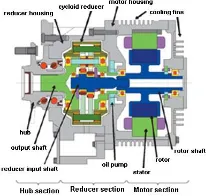
STRUCTURE OF IN-WHEEL MOTOR
The In-wheel motors (also called wheel hub drive, wheel motor, hub motor or the wheel hub motor) is an electric motor which is incorporated into the wheel hub a wheel and drives it directly. In this study, only the effect of the electric motor mass will take into considerations.
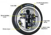
Figure(1) illustrates a cross-section an in-wheel electric motor system, which has a structure that aligns the motor section, reducer section, and the hub section in a series configuration. Figures (2)and(3) illustrate the Michelin active tire with in-wheel electric motor and Bridgestone’s Dynamic-Damping In-wheel Drive System.
Figure 2: Michelin active wheel with in-wheel motor.
Figure3: Bridgestone’s Dynamic Damping In-wheel Motor.
SUSPENSION SYSTEM
In the full vehicle suspension system model, the vehicle body or sprung mass is free to heave pitch and roll, which means the full vehicle dynamics includes the movement and rotation on the vertical, lateral and longitudinal directions; therefore, the vehicle, vertical, lateral, and longitudinal dynamics must be contemplated for a complete vehicle model. The main function of the suspension system is to connect the sprung mass which represents the vehicle body to the four unsprung masses which are front-right, front-left, rear-right rear-left, and wheels. They are free to bounce in the vertical direction relative to the sprung mass.
calculates only the horizontal performance of the vehicle. The vertical model is made seven DOF and four DOF of the four wheels, as obtained in Figure 5. In Figure 4 which represents the horizontal vehicle model, V is the vehicle velocity, is the yaw rate, δ is the front wheel steering angle, and β is the side slip angle. The lengths Lf and Lr indicate the longitudinal
distance from the c.g. to the front wheels and the rear wheels respectively, and Lw is the track width or the lateral distance
between left and right wheels. Let the longitudinal and lateral tire forces given by and respectively, and αij is the slip
angle of the wheel. The superscript or subscript i=f,r refers to the front and rear tires, while the superscript or subscript Fy
and Fx indicates the tire forces. Then the equations of motion of
the vehicle body are:
Figure 4: 3 DOF vehicle model or horizontal model.
Where Iϕ is the moment of inertia of the vehicle about its yaw and m is the vehicle mass.
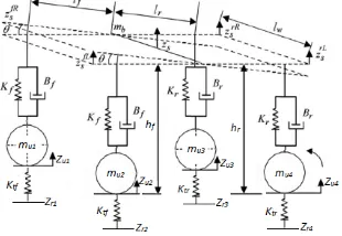
In the vertical model shown in Figure 5, let Zs and are the vertical displacement of the vehicle body at the center and the corner respectively, Zri is the road profile at each tire,
mb is the mass of the vehicle without the mass of the front and
rear wheels mui , θ is the body pitch angle, hi is the vertical
distance from the c.g. to the center of the rear and the front wheel at the equilibrium. The spring and damping constants are Ki and Bi respectively. All the lumped parameters
associated with the passive suspension system.
For a small values of θ and after applying a force balance analysis to the model in Figure 5, the equations of motion can be derived to the equilibrium at static positions. The equations which are describing the sprung mass are:
For rolling motion of the sprung mass:
For pitching motion of the sprung mass:
(5)
For bouncing of the sprung mass:
(6)
Where:
(7)
(8)
(9)
(10)
(11)
(12)
(13)
(14)
And also for each wheel motion in vertical direction: (15)
(16)
(17)
VEHICLE PHYSICAL PARAMETERS
The vehicle parameters values which are used in the paper simulations are listed below in table 1.
Table 1: Full suspension system parameters
Parameter Value Parameter Value
m 1136 Kg Iθ 2.765 Kgm2
mb 1013 Kg Iϕ 614 Kgm2
mu1 63 Kg hf 0.59 m
mu2 63 Kg hr 0.59 m
mu3 60 Kg reff 0.365 m
mu4 60 Kg Kf 36297 N/m
Lf 1.15 m Kr 19620 N/m
Lr 1.65 m Bf 3924 Ns/m
Lw 1.082 m Br 2943 Ns/m
Iφ 2.765 Kgm2 g 9.81 m/s2
SIMULATION RESULTS AND DISCUSSION
This section of the paper presents the suspension system performance. Simulations based on the mathematical model for full car model by using MATLAB/SIMULINK are performed. Performances of the suspension system in term of ride quality, road holding, and car handling are observed, where road disturbance Zri is assumed as the input for the system.
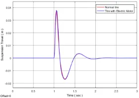
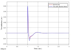
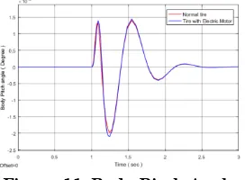
Parameters that observed and obtained are the suspension travel, tire deflection for Front and Left tires, the absolute velocity of the body, and the body pitch angle for full car model. Road disturbance or road profile is taken as a step signal. The main goal of this work is to achieve small amplitude value for the tire deflection and suspension travel.
Figure 6: Suspension Travel of Rear Right and Left tires.
Figure 7: Body Acceleration.
Figure 10: The Absolute Velocity of the Body.
Figure 9: Tire Deflection for Rear Right and Left tires.
Figure 11: Body Pitch Angle.
CONCLUSIONS
This study demonstrates eloquent effects of the In-wheel electric motor mass on the suspension systems performance, some of these effects was clear due to the suspension deflection and sprung mass velocity which represent the road traction and the driver comfort respectively. At same time the study explained that the suspension system with in-wheel electric motor requires a good selection of the vehicle parameters. Finally, it's obvious that from the computer simulations, using of In-wheel electric motor in the vehicles has bad aspects which caused a little reliability to use it.
REFERENCES
[2] Rosheila Darus, “Modelling and control of active suspension for car model,” Master thesis, May 2008.
[3] Hrovat, D. & Tseng, T., “Some Characteristics of Optimal Vehicle Suspensions Based on Quarter Car Model”, IEEE
Proceedings of the 29th Conferences on Decision and Control,
December, Honolulu, Hawaii: IEEE. 1990. 2232-2237
[4]Abdussalam Ali Ahmed, Başar Özkan, “ Using of Fuzzy PID Controller to Improve Vehicle Stability for Planar Model and Full Vehicle Models”, International Journal of Applied
Engineering Research, ISSN 0973-4562 Volume 12, Number 5
(2017) pp. 671-680.
[5]R.Rajamani, “Vehicle dynamics and control”, Springer
Science & Business Media, 2011.
[6]Arjon Turnip, Hanif Fakhrurroja, Hanif Fakhrurroja, “Estimation of the Wheel-Ground Contact tire Forces using
Extended Kalman Filter,” International Journal of
Instrumentation Science,2013, 2(2): 34-40
[7] H. Xiao, W. Chen, H. Zhou, and J. W. Zu, “Integrated vehicle dynamics control through coordinating electronic stability program and active suspension system”, International
Conference on Mechatronics and Automation,2009, pp.
1150-1155.