ISSN (Print) : 2320 – 3765 ISSN (Online): 2278 – 8875
I
nternational
J
ournal of
A
dvanced
R
esearch in
E
lectrical,
E
lectronics and
I
nstrumentation
E
ngineering
(An ISO 3297: 2007 Certified Organization) Website: www.ijareeie.com
Vol. 6, Issue 7, July 2017
Design a RFID Technology based Door
Security System using GSM Module
Karabi Deka1, Raktim Jyoti Gogoi2, Sneha Jhavar3, Hrishikesh Gogoi4
Assistant Professor, Dept. of AEI, Girijananda Chowdhury Institute of Management & Technology, Guwahati,
Assam, India1
UG Student, Dept. of AEI, Girijananda Chowdhury Institute of Management & Technology, Guwahati,
Assam, India 2,3,4
ABSTRACT: Security systems are getting more awareness and importance in last few years. For security reason RFID technology is used for this work. RFID (radio frequency identification) is a technology that combines the use of electromagnetic or electrostatic coupling in the radio frequency (RF) portion of the electromagnetic spectrum to uniquely identify an object, animal, or person. A Multi-Layer Bank Security System is a system for conforming, monitoring and controlling the security at bank locker rooms. This work includes, a door security system using the RFID technology. A microcontroller (AT89S52) in this system which will have two ports, one port is used for the RFID reader (EM-18) and the other one is for the GSM module (SIM900). There will be two levels of security in this system which can be switched by the main user. In the first level, when the RFID card is scanned over the security system box, the card will get detected and if the card is valid then the door will open. If the card is invalid then alarm buzzer will turn on. In the second level if the card is detected, the main user will receive an OTP (one time password) through GSM module (SIM900) and will have to press that OTP to open the door.
KEYWORDS: RFID technologies, GSM Module, Microcontroller, SIM number, LCD.
I.INTRODUCTION
ISSN (Print) : 2320 – 3765 ISSN (Online): 2278 – 8875
I
nternational
J
ournal of
A
dvanced
R
esearch in
E
lectrical,
E
lectronics and
I
nstrumentation
E
ngineering
(An ISO 3297: 2007 Certified Organization) Website: www.ijareeie.com
Vol. 6, Issue 7, July 2017
security system using the RFID technology including a microcontroller (AT89S52) in this system which will have two ports, one port is used for the RFID reader (EM-18) and the other one is for the GSM module (SIM900). When the RFID card is scanned over the security system box, the card will get detected and if the card is valid then the door will open. If the card is invalid then alarm buzzer will turn on. Again if the card is detected, the main user will receive an OTP (one time password) through GSM module (SIM900) and will have to press that OTP to open the door.
II.SYSTEM DEVELOPMENT
The system is providing multiple securities with the help of RFID technology as well as GSM communication. If a user places a valid RFID card near to the RFID reader (EM-18), the RFID reader (EM-18) generates an electromagnetic field through which the RFID card gets powered. Every RFID card return a 12 character long string which consist of 10 character unique ID plus 2 section value. The RFID reader gives the card ID to the microcontroller with the help of serial communication. Whenever the microcontroller read 12 character from the RFID reader it dumps the data in an array of character ,after reading the 12 character, the program executing in the microcontroller compare the ID with a predefined set of card numbers. If the system reads any valid card, it displays the name of the user associated with the specific card. After getting a valid card, the program executing in the microcontroller generate control signal to a motor driver (L293D) .The system is designed in such a way that whenever the motor rotates, it powers up a mechanical arrangement, it may be door or mechanical lock. This system has two limit switches. When the mechanical arrangement hit the first sensor the motor will stop .Similarly another limit switch is used to monitor the limit for closing the door. The motor driver can rotate the motor clockwise as well as anticlockwise .whenever the system is accessed or tried to be accessed, the system sends a message to the registered mobile number (mobile number of the owner) by providing the name of the person who has the valid card or it will send a message to inform unauthorised try for accessing the system. The system is also having a second level security mechanism. If the user or the owner wish to provide the card to a third person for emergency or inevitable situation, the owner can handover the card to any person but at the time of providing the card to any person the owner has to send a message to a specified SIM number which is connected with the device, the message is received by the microcontroller (AT89S52) and check for a valid command. If the owner send a message like ’#otpmode*’, the system will automatically generate a onetime password and is stored. The number is also transmitted to the owner in terms of SMS. If the system is set for OTP mode, it does not allow accessing the system directly, rather after providing the card it will ask for the current OTP. The user has to enter the OTP with the help of 4*4 matrix keypad. After entering the 4 digit OTP, the microcontroller compares the stored OTP with the entered OTP. If both the numbers are matched it will allow accessing the system as well as sending a message to the owner.
The system design of this scheme is divided into two parts: Hardware implementation and Software implementation.
II.1 Hardware Architecture for Control Unit
ISSN (Print) : 2320 – 3765 ISSN (Online): 2278 – 8875
I
nternational
J
ournal of
A
dvanced
R
esearch in
E
lectrical,
E
lectronics and
I
nstrumentation
E
ngineering
(An ISO 3297: 2007 Certified Organization) Website: www.ijareeie.com
Vol. 6, Issue 7, July 2017
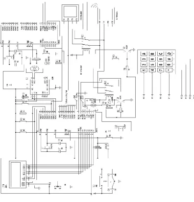
Fig. 1 Circuit diagram
Fig. 1 shows the circuit diagram of the unit. The heart of the system is a microcontroller (8 bit) AT89S52 .it is responsible for monitoring and co-ordinating the RFID reader, GSM modem as well as 4*4 matrix keypad. The entire system requires a regulated +5V except GSM modem and the DC motor. Hence we are using a voltage regulator LM7805. The 7805 has 3 pins. Pin1 is the input pin where we can give +5V to +18V regulated or unregulated power supply (1amp). Pin2 is the ground pin and pin3 is the output pin. Irrespective of input voltage at pin1, the output voltage will be regulated 5(±0.1V). To reduce any noise or ripple from the power supply two 100nF ceramic capacitors are connected across pin 1 and 2 and 2 and 3 of 7805.
ISSN (Print) : 2320 – 3765 ISSN (Online): 2278 – 8875
I
nternational
J
ournal of
A
dvanced
R
esearch in
E
lectrical,
E
lectronics and
I
nstrumentation
E
ngineering
(An ISO 3297: 2007 Certified Organization) Website: www.ijareeie.com
Vol. 6, Issue 7, July 2017
Any microcontroller or microprocessor require clock source to fetch the instructions and execute it. Few microcontroller families has internal oscillator but AT89S52 is not having any clock source, hence we have to use external clock source. Pin 18 and pin 19 of AT89S52 is marked as XTAL2 and XTAL1 respectively. We can use crystal oscillator, function generator, timer circuit or even another microcontroller but crystals are popular with microcontroller as they are reliable, economical and easily available. According to datasheet AT89S52 can operate at 0-33MHz but we have used 11.0592 MHz crystal only as in our project as we are using serial communication. The GSM modem and RFID reader both work through serial communication, but at a time either we can connect with RFID reader or we can connect with GSM modem. Hence a DPDT electromagnetic relay is used to changeover between GSM modem and RFID reader. The pin 10 and pin 11 of AT89S52 i.e. the Rx and Tx pin is connected to the common terminals of DPDT relay where one terminal is connected to Rx pin of GSM module and one terminal is connected to the Tx pin of GSM module. Depending on the status of the relay either it will read from RFID card or it will communicate through GSM modem. To display the status of the system and card holder we are using 16*2 LCD modules. The module is having 16 pins. Pint 1 is ground. Pin 2 is Vcc which is connected to pin 3 of 7805. Pin 3 of LCD is to provide the reference voltage to control the contrast of LCD. The RS, RW and EN pins i.e. pin 4, 5, 6 of the LCD I connected to pins 39, 38, 37 of microcontroller i.e. P0.0, P0.1, P0.2 respectively. AT89S52 is having four ports P0, P1, P2, and P3. The internal pull-up of port 1, 2 and 3 are activated but the internal pull up of port 0 is not activated, hence we must have to use external pull-up if any I/O pin of poet 0is used. Therefore we are using three pull-up resistances R2, R3, R4 of 10KΩ each. Pin (7-14) of LCD is data bus through which we have to send data or command to the LCD. In our circuit we are using port 1 of microcontroller to provide data and command to the LCD. Hence pin (1-8) of microcontroller is connected to pin (7-14) of LCD. Pin 15 and pin 16 of LCD is not having any relation with programming .it is just used to provide backlight of LCD. Hence it is not displayed in circuit diagram.
Pin 9 is reset pin. According to datasheet, if we provide high (+5V) at Pin 9 for two machine cycle (12*2=24 clock pulse), the device will restart and for normal operation, Pin 9 must be pulled down. To create the reset circuit, we have connected a 10kΩ from Pin 9 to ground. A push to momentarily tactile switch is connected across Pin 9 and Vcc. pin 31 is E̅A̅. According to datasheet, if we have to use external memory, Pin 31 must be connected to ground, but to use the internal program memory of AT89S52 (8k) Pin 31 must be connected to Vcc. As we are using internal flash memory, Pin 31 is connected to Vcc.
As we have used a 4x4 matrix keypad to enter the OTP, we use a port which can provide all the 8bit for the matrix keypad. Hence we have kept intact Pin 21 to Pin 28 of microcontroller only for 4x4 matrix keypad. To provide controlling signal to the motor driver, we are using P0.6 and P0.7 (L293D).
A second unit of microcontroller is used in the circuit which is playing a vital role in operation of the circuit. The second DPDT relay as well as send a status pulse to the first microcontroller unit to inform that it has received message from the user (primarily to set the OTP mode). The program executing in first microcontroller continuously monitor the status through P0.5 which is getting signal from the second microcontroller unit receive a signal (message) from the GSM modem, it set P3.3 to low which is connected to P2.5 of microcontroller1. In second unit, we are using the minimal requirement, i.e., any external component are used, i.e., one crystal oscillator, two ceramic capacitor C6-C7, and resistor and capacitor to create the reset circuit.
To controlling the relay, we cannot connect the I/O pin of the microcontroller directly to relay as microcontroller I/O pin can provide low voltage current which is not enough to drive a relay. Hence we are creating two relay circuit based on NPN transistor 2N2222 Phillips.
II.2 Security Unit Software Development
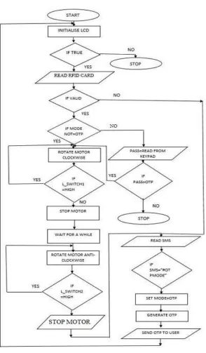
The system software is implemented in C language and the developed code is edited, compiled with Keil software. The flowchart of the algorithm is shown is Fig. 2. The sequential steps in the algorithm for the control unit are as follows.
1. Start.
2. Initialize the display (LCD). 3. Read the card.
4. a) if valid go to step 5.
b) if not valid then go to step 12 .
ISSN (Print) : 2320 – 3765 ISSN (Online): 2278 – 8875
I
nternational
J
ournal of
A
dvanced
R
esearch in
E
lectrical,
E
lectronics and
I
nstrumentation
E
ngineering
(An ISO 3297: 2007 Certified Organization) Website: www.ijareeie.com
Vol. 6, Issue 7, July 2017
b) PASS read from keypad i) If PASS=OTP then go to step 6. ii) If PASS=OTP then go to step 17.
ISSN (Print) : 2320 – 3765 ISSN (Online): 2278 – 8875
I
nternational
J
ournal of
A
dvanced
R
esearch in
E
lectrical,
E
lectronics and
I
nstrumentation
E
ngineering
(An ISO 3297: 2007 Certified Organization) Website: www.ijareeie.com
Vol. 6, Issue 7, July 2017
6. Rotate motor clockwise.
7. Check switches a) if switch1 is high then go to step 6. b) if no then go to step 8.
8. Stop motor.
9. Wait for a while.
10. Rotate motor anticlockwise.
11. a) If switch2 is high then go to step 10.
b) If switch2 is low then display INVALID CARD.
12. Read SMS.
13. If SMS= OTP MODE.
14. Set MODE=OTP.
15. Generate OTP.
16. Send OTP to user and go to step 2. 17. Stop.
III.RESULTS AND ANALYSIS
The security system unit has been tested in the laboratory. It is tested step by step, When the system is turned on, the LCD displays
“Multi-layered security system Developed by
Raktim J Gogoi Hrishikesh Gogoi Sneha Jhavar”.
After this the system displays “Show your card”. When the RFID is brought near the RFID reader (EM-18) which is assigned to any authorised person, for example if the card holder’s name is Raktim J Gogoi who is an authorised person then the LCD displays
“Welcome Raktim J Gogoi”
And the microcontroller (AT89S52) will send a control signal to the motor driver (L293D) which will rotate the motor in one direction. This rotation of the motor will move a mechanical arrangement attached to the door in order to open or close it. We are providing a switch to manually rotate the motor in the opposite direction in order to close the door.
If an invalid card is brought near the RFID reader (EM-18), the LCD will display “Invalid Card
Access denied” and buzzer will turn on.
ISSN (Print) : 2320 – 3765 ISSN (Online): 2278 – 8875
I
nternational
J
ournal of
A
dvanced
R
esearch in
E
lectrical,
E
lectronics and
I
nstrumentation
E
ngineering
(An ISO 3297: 2007 Certified Organization) Website: www.ijareeie.com
Vol. 6, Issue 7, July 2017
Raktim J Gogoi” and the same process will continue. If incorrect OTP is typed then the system will again generate a new OTP and send it to the registered mobile number (number of the owner) and the LCD will display “Enter OTP”.
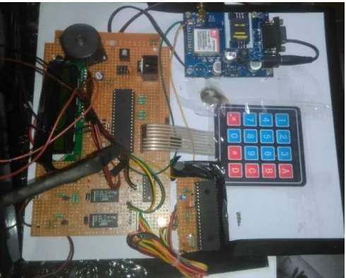
Fig 3: Main Circuit
IV.CONCLUSIONS AND FUTURE WORK
The planning, design, implementation or execution of this work has successfully done in the laboratory. The configuration of the various units into one unit to obtain the desired output of providing door security took the application of the technical (and theoretical) initiative of the Engineering practice to execute. Thus this device has been initiated to provide security by using the RFID technology which is implemented on the door. It allows only authorised people to access the system. It is a demonstration model but it can be implemented in field for security purpose. It can be modified by using biometry and other recognition system also.
REFERENCES
[1] Jifeng Dai and JieZhou, SeniorMember, IEEE,” Multifeature-Based High-Resolution of RFID database and verification of smart card ”,IEEE Transactions on Critical circuit design of RFID Vol.33 No.5.,pp.945-957 May 2011
[2] Bisceglie, M. D. et al. Cooperative Sensor Networks for Voltage Quality Monitoring in Smart Grids, Power Tech, IEEE Bucharest, 1-6, 2010.
[3] Pedro M. Reyes RFID: A Guide to Radio Frequency Identification McGraw-Hill Education,
[4] Syed A. Ahson and Mohammad Ilyas RFID Handbook: Applications, Technology, Security, and Privacy CRC Press, 2008
[5] Umar Farooq, Mahmood ul Hasan, Muhammad Amar, Athar Hanif, and Muhammad Usman Asad,” RFID Based Security and Access Control System”,IACSIT International Journal of Engineering and Technology,Vol.6 No.4.,pp.309-314 August2014
[6] Grewal Kaushal, Rishabh Mishra, Neelam Chaurasiya, Paramdeep Singh, “Rfid Based Security And Access Control System Using Arduino With GSM Module, IJEEE, Vol. 2, No 2, pp. 5-8, April 2015
[7] M. A. Mazidi, J. C. Mazidi, R. McKinlay, “The 8051 Microcontroller and Embedded Systems using Assembly and C”, Second Edition, Pearson, pp. 153-178, 2008