Matrix Converter Control Using Near State
Space Vector PWM Technique
O.Hemakesavulu,
Research Scholar, Department of EEE, Rayalaseema University, Kurnool, Andhra Pradesh, A.P, India
ABSTRACT: Matrix Converters may at once convert an ac power supply of fixed voltage into an ac voltage of variable amplitude and frequency. Matrix Converter is a single stage converter. The matrix converters has following advantages across conventional converters with low volume, sinusoidal input current, bidirectional power flow, minimizing of lower order harmonics and lack of bulky reactive elements. All the reasons lead to the development of matrix converter. Based on the control techniques used in the matrix converter, the performance varies. So this paper analyses the performance of matrix converter with two different modulation techniques such as SVPWM and Near State SVPWM. The basic principle and switching sequence of these modulation techniques are presented in this paper. The output voltage, output current waveforms and THD spectrum of switching waveforms connected to RL load are analyzed by using Matlab/Simulink software. The simulated results are analyzed and shows that the THD is better for Near State SVPWM technique.
KEYWORDS: Matrix Converter, Space Vector Pulse Width Modulation (SVPWM), Pulse Width Modulation (NSVPWM), Total Harmonic Distortion (THD).
I. INTRODUCTION
As demand for energy savings has increased in recent years, inverters are being used in a wider range of applications. Demand for low cost, smaller size and higher efficiency will continue to further expand the range of inverter applications. However, as a trend towards eco-friendly products increases, some sort of measure is necessary to suppress the harmonics present in the inverter input current. In power electronic applications direct AC/AC conversion plays an important role. This direct AC/AC conversion provides inherent attractive characteristics. The need to increase the quality and the efficiency of the power supply and the power usage, the three phase matrix converters becomes a modern energy converter and has emerged from the early conventional energy conversion modules. The matrix converter is an alternative to a inverter drive for a frequency control. The matrix converter is also known as an ‘all-silicon solution’. The matrix converter is a single stage converter which does not require any capacitor as the dc-link energy storage component. The capacitor can be a critical component because it is large and expensive. In addition, the matrix converter has a high power factor sinusoidal input current with a bi-directional power flow for the whole matrix converter drive system. It has longer life because no capacitor is used.It has many advantages over rectifier fed inverter system. Different switching schemes for an ac/ac matrix converter have been proposed to achieve sinusoidal input and output current waveforms. Several publications on matrix converters have dealt with the modulation strategies to improve the performance of the matrix converter [1].
II. MATRIX CONVERTER
A matrix converter is a variable amplitude and frequency power supply that converts the three phase line voltage directly into three phase output voltage. It is very simple in structure and has powerful controllability.
Fig.1: Three Phase Matrix Converter
III. PULSE WIDTH MODULATION
Because of advancements in solid state power devices PWM based converters are most widely used in drives.PWM inverters makes it possible to control both the frequency and magnitude of the voltage and current applied to drive the motor. The energy that a PWM converter delivers to a motor is controlled by PWM signals applied to the gates of the power switches. Different PWM techniques exist, that are Sinusoidal PWM, Hysteresis PWM and the relatively new Space-Vector PWM. These techniques are commonly used for the control of ac induction, Brushless Direct Current (BLDC) and Switched Reluctance (SR) motors. As a result, PWM converter powered motor drives offer better efficiency and higher performance compared to fixed frequency motor drives.
The generation of PWM pulse requires reference sine wave and triangular wave. The reference sine wave is compared with the feedback from the output voltage, is amplified and integrated as shown in figure 3. This signal is then compared with a generated triangular wave. The rectangular wave is the result of this comparison. As the sine wave is reaching its peak, the pulses get wider as show in figure 4. It is clearly visible that the duty cycle of the rectangular wave is varying according to the momentary value of the required output voltage. The result is that the effective value of the rectangular wave is the same as that of the output voltage. This pulse is used to switch ON or OFF the power switches. The width of the pulse or duty cycle can be varied by varying the frequency of the reference wave.
IV.SPACE VECTOR MODULATION
The concept of space vector is derived from the rotating field of AC machine. In this technique the three phase quantities can be transformed into two phase quantities in a d-q frame. The d, q components are found by Park transform, where the total power, as well as the impedance, remains unchanged. The magnitude of each active vector (V1to V6) is 2/3 Vdc (dc bus voltage). SVPWM [5] based converters supplies the AC machine with the desired phase voltages. The space vector modulation concept is used to calculate the duty cycle of the switches which is imperative implementation of digital control theory of PWM modulators. The space vector pulse width modulation technique has the following advantages when compared to the conventional PWM technique.
Its maximum output voltage is 15.5% greater, The number of switching required is about 30% less
The modulating signal is generated by injecting selected harmonics to the sine wave. This results in flat-topped waveform and reduces the amount of over modulation. It provides a higher fundamental amplitude and low distortion of the output voltage. The modulating signal is generally composed of fundamental plus harmonics.
The concept of space vector is derived from the rotating field of ac machine which is used for modulating the converter output voltage. In this modulation technique the three phase quantities can be transformed to their equivalent two phase quantity either in synchronously rotating frame (or) stationary d-q frame. From this two phase component, the reference vector magnitude can be found and used for modulating the converter output. SVM treats the sinusoidal voltage as a constant amplitude vector rotating at constant frequency. This technique approximates the reference voltage Vref by a combination of the eight switching patterns (V0 to V 7). The representation of rotating vector in
complex plane is as shown in figure 3.
Fig.3: Representation of Rotating Vector in Complex Plan
V. NEAR STATE SPACE VECTOR MODULATION
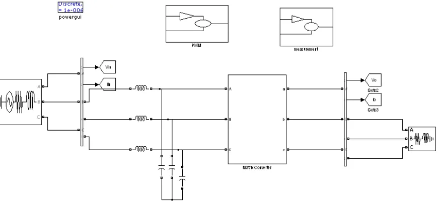
VI.MODELING OF MATRIX CONVERTER
Implementation of the matrix converter is done using Matlab / Simulink tools. The different modulation techniques are used to provide the pulses for the matrix converter. The converter consists of nine modular H-bridge capacitor clamped switch cells, as illustrated in figure 4 connected from each input phase to output phase. The ac supply is given to the H- bridge switch cell through the filter circuit. Each switch cell consists of four IGBTs and one capacitor. The gate pluses for the switches are given through the PWM pulse circuits.
Fig 4 :Simulink diagram of H-Bridge Switch Cell with Capacitor.
VII. SIMULATION RESULTS AND DISCUSSION
The proposed control algorithm is tested with an ideal nine-switch three phases to three phase matrix converter feeding a RL load. For this purpose, digital simulations are carried out using Matlab / Simulink software. The simulation parameters are set as; the supply frequency = 50Hz, the input voltage = 480 V, the input current = 27 A, the
switching frequency = 2 kHz, resistance =20 Ω, inductance =310 mH.
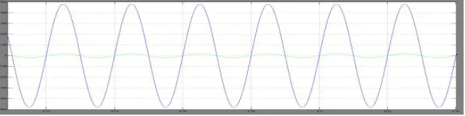
Fig.6:Input Voltage and Current Waveforms in Steady State Condition
Figure 6 shows the input voltage and current waveform given to the matrix converter. The input voltage and current is same for both the modulation techniques.
Fig.7:.PWM Pulses for Upper and Lower Switches of Phase A
Fig.9: Output Voltage and Current Waveform of Matrix Converter using Near State SVPWM Technique
Fig.10: Harmonic Profile of Output Voltage Employing SVPWM Technique
TABLE.1. PERFORMANCE COMPARISON OF SVPWM, NEAR STATE SVPWM TECHNIQUES
S.No Parameter SVPWM Near State SVPWM
1 THD 4.72 3.60
VIII. CONCLUSION
The proposed Matrix Converter with different modulation techniques was simulated using Matlab/ Simulink model blocks. PWM, SVPWM,Near State Space Vector PWM techniques were analyzed in detail and the outputs were presented. The pulses obtained from various schemes are used to control the output parameters of the matrix converter to convert a given three phase input voltage into a three phase output voltage of a desired frequency and magnitude. Compared to SVPWM, Near State SVPWM technique has better voltage transformation capability. The major disadvantage of the matrix converter can be overcome by eliminating third harmonics by injecting third harmonic voltage.
REFERENCES
[1] Patrick W.Wheeler, Jose Rodriguez,Jhon C. Clare, Lee paper title Empringham and Alejandro Weinstein, “Matrix Converters: A Technology Review”, IEEE Transactions on Industrial Electronics, Vol.49, Issue 2, pp. 276-288, April 2002.
[2] J.Karpagam, Member IEEE, Dr.A.Nirmal Kumar and V.KumarChinnaiyan, “Comparison of Modulation Techniques for Matrix Converter”, IACSIT International Journal of Engineering and Technology, Vol.2,No.2, April 2010 ISSN: 1793-8236.
[3] Apap, M. Clare, J.C. Wheeler and P.W. Bradley, K.J. “Analysis and Comparison of AC-AC Matrix Converter Control Strategies”, PESC03, IEEE 34th Annual conference on Power Electronics, Vol. 3, pp. 1287-1292, June 2003.
[4] Shimada, H. and Takeshita, T. “Matrix Converter Control using Direct AC/AC Conversion Method for Reducing Output Voltage Harmonics” APEC06, IEEE 21st Annual Conference on Applied Power Electronics, Vol. 1, pp. 7-13, March 2006.
[5] B. K. Bose, “Expert system, fuzzy logic, and neural network applications in power electronics and motion control,” in Proc. IEEE PEMC’94, pp. 1303-1323,1994.
[6] P. Kirawanich and R. M. O. Connell, “Fuzzy logic control of an active power line conditioner,” IEEE Trans. on Power Electron., vol. 19, no. 6, pp. 1574-1585,2004.