FPGA Implementation of 3D DCT Requiring
Only 14 Additions
Nishi.G.Nampoothiri 1, Sibin Johny.2
Associate Professor, Department of ECE, MUSALIAR College of Engineering & Technology, Pathanamthitta, Kerala,
India1
PG Scholar, Department of ECE, MUSALIAR College of Engineering & Technology, Pathanamthitta, Kerala, India 2
ABSTRACT: High quality digital video in multimedia devices and cognitive radio networks are experiencing exponential growth. Therefore the demand for applications involved in such potential areas is technically expanding. Significant effort is been made to realize DCT computations utilizing minimal configuration resources at acceptable accuracy and meeting timing constraints which can be highly explored for their effective use in these streams. The proposed digital hardware architectures are intended to implement fast algorithms that reduce computational complexity, area and power consumption and also to improve the speeds of operation. Video processing systems such as HEVC requiring low energy consumption needed for the multimedia market has lead to extensive development in fast algorithms for the efficient approximation of 3D DCT transforms. The DCT is employed in a multitude of compression standards due to its remarkable energy compaction properties. Multiplier free approximate DCT transforms have been proposed to offer superior compression performance at very low circuit complexity. Such approximations can be realized in VLSI hardware using additions and subtractions only, leading to significant reductions in chip area and power consumption compared to conventional DCTs and integer transforms. In this paper, we introduce 8-point DCT approximation that requires only 14 addition operations and no multiplications. The proposed DCT can be used in reconfigurable video standards such as HEVC. Circuit complexity of DCT is measured using FPGA based rapid prototypes on Xilinx Sparatan6 devices and also simulated up to synthesis level for application specific integrated circuits (ASICs).
KEYWORDS: Discrete Cosine Transform, FPGA, HEVC, ASIC.
I.INTRODUCTION
II.RELATED WORKS
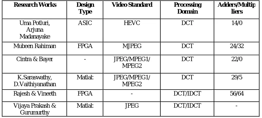
The table shown below describes the survey of literature. Some of the previous papers in this particular field are discussed here. Most of them are adopted DCT as the compression method due to its energy compaction and separability properties. In the proposed design, the major consideration is the number of adders and multipliers. The previous methods were used a number of adders with additional multipliers to achieve the complete design, but here in the modified design, a multiplier free design with reduced number of adders is implemented.
Table 1: Literature Survey
The conventional methods for image and video compression technique use DCT having 32 adders and 24 multipliers. Also in order to remove the temporal and spatial redundancy, Motion estimation and Motion compensation were performed. In the existing system, in order to reduce the size of the ASIC, the architecture proposed a design that includes only 14 adders, but they didn’t focused in the implementation of the system for the purpose of image and video compression using 3D DCT. Instead, the system has followed the traditional methods that include modules like 2D DCT, motion estimation and summation in order to reduce the spatial redundancy. We studied those designs and implemented them with suitable design tools. The primary objective of this project was the design and implementation of 3D DCT in compression system, this study focuses on the design of more than one module like quantization, zigzag scanning, run length encoding and Huffman encoding.
III.MODIFIED SYSTEM
The 3D DCT motion compression algorithm relies on a different principle for the compression of the MJPEG information. A continuous tone image can be represented as a two dimensional array of pixel values. The Discrete Cosine Transform (DCT) converts two dimensional images from spatial to frequency domain. In spatial representation the energy distribution of pixels is uniform, while in the frequency domain the energy is concentrated into low frequency coefficients. Pixels in full motion video are also correlated in the temporal domain and the FDCT will concentrate the energy of pixels in the temporal domain just as it does in the spatial domain.
Research Works Design Type
Video Standard Processing Domain
Adders/Multip liers
Uma Potluri, Arjuna Madanayake
ASIC HEVC DCT 14/0
Mubeen Rahiman FPGA MJPEG DCT 24/32
Cintra & Bayer - JPEG/MPEG1/
MPEG2
DCT 22/0
K.Saraswathy, D.Vaithiyanathan
Matlab JPEG/MPEG1/
MPEG2
DCT 29/5
Rajesh & Vineeth FPGA - DCT/IDCT 56/64
Vijaya Prakash & Gurumurthy
Fig 2: Modified Architecture
The major concern is the number of adders and multipliers that are used and the power consumed by the design. This can be further simplified as in, which focuses more on reducing the number of adders and multipliers to decrease the net power consumed by the design and to decrease the number of gates in the design. We chose DCT with 14 adders and make it suitable for the implementation of 3D DCT. We aim at deriving a low complexity approximate DCT. For that, we propose a search over the 8x8 matrix space in order to find candidate matrices that possess low computation cost. Thus we have the following optimization problem:
T* = arg min cost(T)
The solution of ‘T*’ is the following DCT approximation: C* = D*.T*
D* = diag (1/√8, 1/√2, 1/2, 1/√2, 1/√8, 1/√2, 1/2, 1/√2) ; T* = P4.A12.A11.A1;P4-the permutation (1)(2 5 6 8 4 3 7).
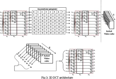
Fig 3: 3D DCT architecture
The first section of fig.3 shows the 2D DCT architecture. Each row of 8x8 matrix will take into 1D DCT. The output will fed into the transposition buffer. Again a column wise 1D DCT is performed. After completing the 2D DCT process for the complete frame, the 0th position values from each of the 8x8 matrix will again applied into 1D DCT to get the complete 3D DCT as shown in the second part of fig.3. It avoids the conventional complex architectures such as motion estimation and summation and simplifies the 3D DCT using only 14 adders.
IV. OVERVIEW OF THE VIDEO COPMPRESSION SYSTEM
The general block diagram of the modified system comprises of three main modules:
Fig 4: Block Diagram of the video compression system
1. Video Stream – Basically consists of pixel values of the input video.
2. A Video compression or video encoder unit – This unit includes 3D DCT and Quantization block. 3. Entropy encoder unit- Contains units such as zigzag scan, run length encoding and Huffman coding.
entropy coding, unlike lossy compression, as in the colour space, DCT and quantization procedures, the entropy coding compression is lossless. The zigzag process is an approximate ordering of the basic functions from low to high spatial frequencies. This process will give more compression by putting more order in the entropy. Essentially lower frequency components, which describe the gradual luminance changes, are more important to the human visual system than the high frequency changes. By ordering the more important coefficients in the beginning of the 8x8 block, we can expect more runs of zeros later after quantization, toward the end of the 8x8 block. The first step in entropy coding is known as run length coding. This is a simple thought that is accomplished by assigning a code, run length and size, to every non-zero value in the quantized data stream. The run length is a count of zero values before the non-zero value occurred. The size is a category given to the non-zero value which is used to recover the value later. The DC value of the block is omitted in this process. Additionally, with every non-zero value a magnitude is generated which determines the number of bits that are necessary to reconstruct the value. It will indicate possible values in the size category that can be correct. Run Length coding is a basic form of lossless compression. Essentially, this process is a generalization of zero suppression techniques. Huffman coding is a technique which will assign a variable length codeword to an input data item. Huffman coding assigns a smaller codeword to an input that occurs more frequently. It is very similar to Morse code, which assigned smaller pulse combinations to letters that occurred more frequently. Huffman coding is variable length coding, where characters are not coded to a fixed number of bits. This is the last step in the encoding process. It organizes the data stream into a smaller number of output data packets by assigning unique code words that later during decompression can be reconstructed without loss. For the JPEG process, each combination of run length and size category, from the run length coder, are assigned a Huffman codeword.
V. SIMULATION RESULT
Pixel values are given as input to the 3D DCT. Here values from 8 frames are given to the 3D DCT. The first step of compression is performed in 3D DCT. The output of the 3D DCT is then fed into the quantization part where the size of the data is reduced. Quantization involved in image processing, is a lossy compression technique achieved by compressing a range of values to a single quantum value. Dividing the DCT coefficient matrix element wise with this quantization matrix, and round to integers. Output from the quantization block is then undergoes Zigzag scanning, where ordering of the coefficients from low to high spatial frequencies takes place. This process will give more compression by putting more order in the entropy. By ordering the more important coefficients in the beginning of the 8x8 block, we can expect more runs of zeros later after quantization, toward the end of the 8x8 block.
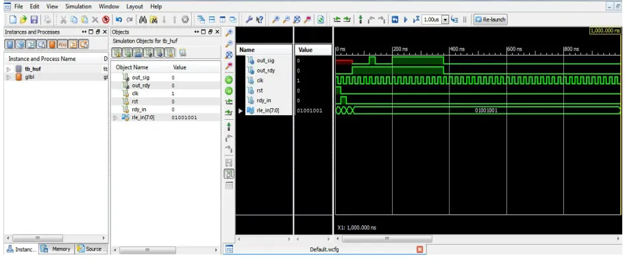
Fig 5: Final o/p as bit streams
variable length code word to an input data item. Huffman coding assigns a smaller codeword to an input that occurs more frequently. This is the last step in the encoding process. It organizes the data stream into a smaller number of output data packets by assigning unique code words that later during decompression can be reconstructed without loss.
V.CONCLUSION
In this work, the design and implementation of a low power and low cost hardware based image and video compression system is proposed. The system is designed in such a way so as to be integrated within the surveillance video camera to compress the captured video footage before transmission through the link. The purpose of the designed system is to enable the real time compression of the captured video stream without significant increase in the hardware resources and power consumption. The compression system was designed to fulfil implementation goals. In this project 3D DCT replaces Motion Estimation and 2D DCT and perform temporal and spatial redundancy with the help of a single module. The 14 adder implementation is used to reduce the computation time and complexity of the image and video compression system. The hardware design of this compression system also maintained low power, low hardware cost with satisfactory processing speed which was the implementation goals. In comparison with other works on hardware video compression system, this system features low FPGA resources and high processing speed and low hardware cost. Design of the hardware architecture of a novel digital video compression system to motivate processing of video stream in real time was presented in this project. FPGA based prototyping for the hardware architecture was developed. The proposed system was suitable for implementation using an FPGA and can be used as a part of an ASIC. In the current implementation, FPGA was the simple and available way of the proof of concept. The aim of this project was to achieve two objectives. To propose a new HW architecture of a digital compression system for real time video processing and making it suitable for VLSI implementation. Second, to ensure that the compression algorithm works with a FPGA with minimum resources. Contradictory to existing solutions, the modified design replaces 24 adders by a number of fourteen and completely avoids multipliers and provides a simple and robust implementation.
REFERENCES
1. Uma Sadhvi Potluri, Arjuna Madanayake, Member, IEEE, Renato J. Cintra, Senior Member, IEEE, FábioM. Bayer, Sunera Kulasekera, and
Amila Edirisuriya, “Improved 8-Point Approximate DCT for Image and Video Compression Requiring Only 14 Additions”, IEEE Transactions on Circuits and Systems—I: Regular papers, vol. 61, pp. no. 6, June 2014.
2. U. S. Potluri, A. Madanayake, R. J. Cintra, F. M. Bayer, and N. Rajapaksha, “Multiplier-free DCT approximations for RF multi-beam digital
aperture-array space imaging and directional sensing,” Meas. Sci. Technol., vol. 23, no. 11, pp. 1–15, Nov. 2012.
3. S. Bouguezel, M. O. Ahmad, and M. N. S. Swamy, “Low-complexity 8x8 transform for image compression,” Electron. Lett., vol. 44, no. 21,
pp. 1249–1250, 2008.
4. Arjuna Madanayake, Member, IEEE, Renato J. Cintra, Senior Member, IEEE, Denis Onen, Senior Member, IEEE, Vassil S. Dimitrov, Nilanka
Rajapaksha, L. T. Bruton, Fellow, IEEE, and Amila Edirisuriya “A Row-Parallel 8×8 2-D DCT Architecture UsingAlgebraic Integer-Based Exact Computation”, IEEE Transactions on Circuits and Systems for Video Technology, vol. 22, pp. no. 6, June 2012.
5. Renato J. Cintra, Senior Member, IEEE, and Fábio M. Bayer “A DCT Approximation for Image Compression”, IEEE Signal Processing
Letters, vol. 18, pp. no. 10, October 2011.
6. E.Magli and D. Taubman, “Image Compression Practices and Standards for Geospatial Information Systems,” in Proc. IEEE Int. Geo Science
and Remote Sensing Symposium (IGARSS), vol. 1, pp. 654–656, Jul. 2003.
7. H. Zheng and J. Boyce, “Packet Coding Schemes for MPEG Video Over Internet and Wireless Networks,” in Proc. IEEE Wireless
Communication Networking Conf. (WCNC), vol. 1, pp. 191–195, 2000.
8. M. Rezaei, S. Wenger, and M. Gabbouj, “Video Rate Control for Streaming and Local Recording Optimized for Mobile Devices,” in Proc.