Implementation of Oscillator Using Current Controlled
Current Conveyor at 120nm Technology
Neetu narwariya#1, Deepak sharma*2 #
Electronics & Communication, R.G.P.V Bhopal L.K.C.T. Indore M.P. India
Abstract—Current Conveyors have been used as a basic building block in a variety of electronic circuit in
instrumentation andcommunication systems. Today they replace the conventional OPAMP in so many
applications such as active filters, oscillators, analogsignal processing and A/D, D/Convertors. Current conveyor is
a high performance analog circuit design block based on currentmode and voltage mode approach. It is basically
a unity gain element that exhibits high linearity, wide dynamic range, highbandwidth and better high frequency
performance. The current conveyor is a combination of voltage as well as current follower.Current conveyor has
the advantages of a wide current and voltage bandwidths. We use a translinear configuration for first,second and
third generation current conveyor. Here, Sinusoidal oscillator by using CCI CCII and CCIII perform good
accuracy andfrequency response at 1.5V supply voltage. The current conveyor is simulated in terms of voltage
offset, current offset, currentbandwidth and voltage bandwidth in 120nm CMOS technology using TANNER
Tools.
Keywords—Voltage Mode Circuits (VMC), CMOS Current Conveyor, CCII, and Miscellaneous symbolic representation of
CCII
1.
Introduction
A current conveyor is a four (possibly five)
terminal device which arranged with other
electronics elements in a specific circuit
configuration can perform several analog
processing functions like traditional op – amp.
This stems from the fact that the CC offers an
alternative way of abstracting complex circuit
function, thus aiding in the creation of new and
useful implementations. Moreover likewise op –
amp the terminal behaviour of op – amp
approaches its ideal behaviour quite closely.
Hence the circuit designed with CC matched the
predicted theoretical values. The concept of
current conveyor was first presented in 1968[1]
and further developed to a second generation
current conveyor in 1970[2].The current
conveyor is intended as a general building block
as with the operational amplifier. Because of the
operational amplifier concept has been current
since the late 1940’s, it is difficult to get any
other similar concept widely accepted. However,
operational amplifiers do not perform well in
application field for current conveyor circuits.
Since current conveyors operate without any
global feedback, different high frequency
behaviour compared to operational amplifier
higher voltage gain over a large signal bandwidth
under small or large signal conditioning than a
corresponding op – ampcircuit in effect a higher
GBW product. In addition, CCs have been
extremely successful in the development of an
instrumentation amplifier which doesn’t depend
critically on the matching of external
components, instead depends only on the
absolute value of signal component.
2.
Voltage Mode Circuits (VMC)
The current mode design technique is a good
alternative for the high performance analog
circuit design as it offers voltage independent
high bandwidth. In current-mode design, the
stress is more on the current levels for the
operation of the circuits and the voltage levels at
various nodes are immaterial. In voltage-mode
circuits (VMCs), such as operational amplifiers
(op amp), the performance of the circuit is
determined in terms of voltage levels at various
nodes including the input and the output nodes.
Therefore, VMCs are not suitable for high
frequency applications. When signals are widely
distributed as voltages, the parasitic capacitances
are charged and discharged with the full voltage
swing, which limits the speed and increases the
power consumption of voltage mode circuits.
Current-mode circuits cannot avoid nodes with
high voltage swing either but these are usually
local nodes with less parasitic capacitances [5].
Therefore, it is possible to achieve higher speed
and lower dynamic power consumption with
current-mode circuit techniques. When the signal
is conveyed as a current, the voltages in MOS
transistor circuits are proportional to the square
root of the signal, if the devices are assumed to
be operating in saturation region. Therefore, a
compression of voltage signal swing and a
reduction of supply voltage are possible. This
feature is utilized in log domain filters, switched
current filters and in non-linear current-mode
circuits [6]. However, as a result of the device
mismatches, this non-linear operation may
generate an excessive amount of distortion and
cannot be used for the applications where high
linearity is required. Thus, linearization
techniques are utilized in current-mode circuits
to reduce the nonlinearity of the transistor
trans-conductance and in this case the voltage signal
swing is also not reduced.
3.
Basic
Principle
of
Sinusoidal
Oscillator
The basic structure of a sinusoidal oscillator
consists of anamplifier and a frequency selective
network connected inpositive-feedback loop.
Although in an actual oscillatorcircuit, no input
signal will be present, we include an inputsignal
here to explain the principle of operation.
Withexception such as relaxation oscillator, the
operation ofoscillator is based on principle of
positive feedback whereportion of the output
signal is feedback into input withoutphase
change. Thus, it reinforces the input and
this, the phaseshift of feedback signal must be
either 0o or 360o. Thelast requirement is the loop
gain T of amplifier must beequal to one, which is
also named as Barkhausencriterion. Thus
mathematically, the loop gain T is
T =AVβ= 1
Where AV is the voltage gain of the amplifier
and betais the feedback at output voltage. An
oscillator enjoys thesame status in the domain of
electrical and electronicsengineering as do
wheels in the mechanical engineering.Sinusoidal
Oscillators of variable frequency find widerange
of applications in instrumentation &
measuringsystems, communication, control
systems and signalprocessing. For the
implementation of RC
(resistancecapacitance)sinusoidal oscillator. As
we Compared thesinusoidal oscillator by using
first, Second and thirdgeneration of current
conveyor then second generationcurrent
conveyor iis the best among these.
4.
Sinusoidal Oscillator by using CCII
Sinusoidal oscillator by using Second generation
currentconveyor is the best one as compared with
first and thirdgeneration of current conveyors. A
second generation currentconveyor (CCII) based
resistance-capacitance (RC)sinusoidal oscillator
operating over wide range. Theoscillation
condition and oscillation frequency can
beadjusted independently by two control
resistors. The leakagepower consumed by
CMOS based Second generation
currentconveyor (CCII) is 9.5mW.Sustained
oscillation obtained at3MHz. The circuit
proposed makes use of groundedcapacitors the
circuit enjoys low sensitivities and suitable
forintegration. Sinusoidal oscillator of variable
frequency finedextensive applications in
communication systems,instrumentation and
measurement. The simplicity of thedesign
approach turns into a disadvantage when it is
desiredto change the frequency of oscillation
independent of thenecessary and sufficient
condition required to sustain theoscillations.
Here, the sinusoidal oscillator by using CCII
isdesign by the miscellaneous symbol of CCII,
which isgenerated by the schematic of CCII as
shown in fig.1 and
Figure 1: Schematic designing of CCII
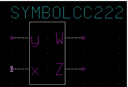
After the designing of Second-generation current conveyor(CCII) its symbol is designed by selecting
the whole circuitby using the Mentor Graphics tools and coping it in thenew schematic by a new
name and in miscellaneous pressthe option of generate symbol then first generation currentconveyor
miscellaneous symbol will be generated asshown in fig.2
output (DO-CCII). After the miscellaneous symbolicrepresentation of CCII, that symbol is also
called as the blackblock representation. Here, by this symbol we will designsinusoidal oscillator as
shown in fig.3. The secondgeneration current conveyor (CCII) is sometimes claimed asthe standard
building block of current mode operation whichstems largely from the fact that the CCII offers a
useful wayof realizing complex circuit functions. In the recent years,their applications and
advantages in the RC sinusoidaloscillators with the salient features of controlling thefrequency of
oscillation without affecting the condition foroscillation have received considerable attention [3].
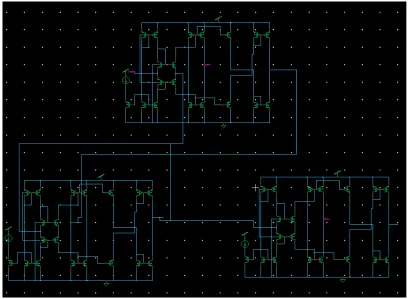
Theproposed RC sinusoidal oscillator using second generationcurrent conveyor (CCII) with
grounded capacitor is as shownbelowFigure 3:
Figure 3 schematic of oscillator using CCII
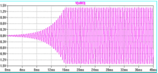
The output waveforms presented and the results discussed inthis are simulated outcomes of the
proposed circuit carriedout by use of mentor graphic 0.18um technology. Delay inthe start of
oscillation=40ns, Frequencyachieved=3MHz and Amplitude achieved-664.13mV.Simulation result
Figure 4: Waveform of Sinusoidal oscillator by using CCII
CONCLUSION
We presented a CMOS implementation current
conveyor based oscillator circuit in 120nm
CMOS technology. The design, based on a
±1.5V DC supply and developed using
TANNAR tool, achieves good linearity, low
power dissipation and high bandwidth in the
device.
A proposed CMOS second generation
basedsinusoidal oscillator has been described and
simulate up to a maximum frequency of
3MHz.The circuit follow theinput-output
characteristics of second generation
currentconveyor(CCII).R1=R2=R=9.2KΩ,C1=C
2=C=120PF andRf=3.2 KΩ under the condition
Rc=5.2 KΩ.
REFRENCE
[1] K. smith, A. sedra “the current conveyor
a new circuit building block,” IEEE proc., vol.
56, 1368-69, 1968.
[2] A. sedra K. smith, “a second generation
current conveyor and its applications,” IEE trans.
Vol. 17, pp. 132-134, 1970.
[3] D. Frey, “log domain filtering an
approach to current mode filtering,” IEEE
proceedings G, vol. 140, pp. 406-416, dec 1993.
[4] B. Wilson, “recent developments in
current conveyors and current mode circuits,”
proc. Inst. Elect, eng, vol. 137, pt. G, PP. 63-77,
apr. 1990.
[5] Induprabhasingh, kalayansingh and S.N.
Shukla, “current conveyor, novel universal active
block,” 3S-JPSET, vol. issue 1, pp. 646-650,
2010.
[6] toumazou, F. J. lidgey, D. G. Haigh,
London peter peregnirus Ltd, vol. 38, pp.
646-650, 1990.
[7] N. Bouaziz, EI Feki and D. S. Masmoudi,
“high performance dual output second and third
generation current conveyor and current mode
multifunction filter application” vol. 8, pp.
4244-4346, 2009.
[8] Rao, M.K.N, and HASLETT, J. W, “a
modified current mirror with level shifting
capability and low input impedance” IEEE J.,
SC-14, pp. 762-764, 1979.
[9] Rana and K. Pal, “current conveyor
simulation circuit using operational amplifiers”
journal of physical science, vol. 11, pp. 124-132,
2007.
[10] A. Fabre, “third generation current
conveyor, a new helpful active element”
electronics letters, vol. 31, pp.338-339, march
1995.
[11] huertas, J. L., “circuit implementation of
current conveyor” electronics letters, vol. 16, pp.
225-226, 1980.
[12] W. Chiu, S. I. Liu, H. W. Tsao, and J. J
Chen, “ CMOS differential difference current
conveyor and their application” IEE proc. Circuit
device syst, vol. 143, pp. 91-96, 1996.
[13] Alzaher, H. A., Elwan, H.o. and Ismail,
M., “CMOS fully dofferential second generation
current conveyor” electronics letters, vol. 36, no.
13, pp. 1095-1096, 2000.
[14] Kumar, “current conveyor, a review of
state of the art,” IEEE circuit &syst, mag, vol. 3,
pp. 10-13, 1981.
[15] Wilson, “recent developments in current
conveyors and current mode circuits” IEE proc.,
vol. 137, pp.63-77, 1999.
[16] D.R.Bhaskar, V.K.Sharma, M.Monis and
S.M.I.Rizvi, “new current conveyor and its
application” microelectronics journal, vol. 30, pp.
837-839, 1999.
[17] F. Lidgey Current Follower Wireless
world vol. 90, pp. 40-43, 1984.
[18] A. Fabres, O.Saald, “high frequency
applications based on new current controlled
conveyors IEEE, Transaction on circuit and
system” fundamental theory and application vol.
43, pp. 82-91 1996.
[19] Zia Abbas, GiusepppeScotti and Mauro
Olivieri, World Academy Science, Engineering
and Technology “Current Controlled Current
Conveyor (CCCII) and Application using 65 nm
CMOS Technology” Vol. 79, PP. 935-939, 2011.
[20] S. Minaei and S. Turkoz, “Current-mode
electronically tuneable universal filter using only
Plus-type current controlled conveyors and
ground capacitors.” ETRI Journal, vol. 26, PP.
292-296, 2004.
[21] M0urina Ghosh, Subhajit Bhattacharya,
Ashish Ranjan, Sajal K. paul “CMOS Sinusoidal
Colloquiums on Computer Electronics Electrical
Mechanical and Civi2011© 2011 ACEEE DOI:
02, 01. Poster Paper PP. 142-144, CEMC. 2011.
[22] Anwar A. Khan, Senior Member, IEEE,
SadanandBimal, K. K. Dey, and S. S. Roy,
“Novel RC Sinusoidal Oscillator Using
Second-Generation Current Conveyor” IEEE, vo1.9, PP.
435-439, 2010.
[23] PipatPrommee, MontriSomdunyakanol,
and KritAngkeaw CCCII based Multiphase
Sinusoidal Oscillator Employing High-Pass
Sections IEEE, vol. 9, PP. 3978-4244-3388,
2009.
[24] N. Pandey, S. K. Paul, “A novel
electronically tuneable sinusoidal oscillator
based on CCCII (-IR)”, J. of Active and passive