A Solar-Powered Induction Motor with
Maximum Power Point Tracking
Implemented On a Low-Cost
PIC-Microcontroller
Vikas V. Kulkarni1, Bhushan L. Sonawane2
Professor [Power Electronics & Drives], Dept. of Electrical Engg, AISSMS, COE, Pune, India1
PG Student [Power Electronics & Drives], Dept. of Electrical Engg, AISSMS, COE, Pune, India2
ABSTRACT: This dissertation presents the design, simulation and analysis of a Solar powered Battery Charger & Induction Motor using MPPT method. Fossil fuels are a relatively short-term energy source; consequently, the uses of alternative sources such as solar energy are becoming more wide spread. To make solar energy more viable, the efficiency of solar panel systems must be maximized. A feasible approach to maximizing the efficiency of solar panel systems is sun tracking. Proposed in this report is a system that is solar panel that is directed towards the sun-rays so that more and more amount of sun-rays are absorbed by Solar cells which then converts them into electricity.
The compactness of the proposed solar system enables it to be mounted onto the wall. The sunrays are absorbed by the surface of the photovoltaic panel. The PV panel absorbs more & more rays coming from sun during the day (mostly in summer). A computer model of the solar MPPT system is modelled using MATLAB/Simulink. The efficiency over the fixed solar panel, the power generated and the types of PV systems to achieve the required level of efficiency can be determined before actual implementation. The experimental testing shows some agreement with the simulation results.
KEYWORDS: PV ARRAY, MPP, MPPT, PIC, LCD, FLC, etc.
I. INTRODUCTION
As the range of applications for solar energy increases, so does the need for improved materials and methods used to harness this power source. There are several factors that affect the efficiency of the collection process. Major influences on overall efficiency include solar cell efficiency, intensity of source radiation and storage techniques. The materials used in solar cell manufacturing limit the efficiency of a solar cell. This makes it particularly difficult to make considerable improvements in the performance of the cell, and hence restricts the efficiency of the overall collection process. Therefore, the most attainable method of improving the performance of solar power collection is to increase the mean intensity of radiation received from the source. There are three major approaches for maximizing power extraction in medium and large scale systems. They are sun tracking, maximum power point tracking or both.
I. Solar Power in India : In July 2009, India unveiled about US$19 billion plant to produce 20 GW of solar power by 2020. Under the plan, the use of solar-powered equipment and applications would be made compulsory in all government buildings, as well as hospitals and hotels. On November 18, 2009, it was reported that India was ready to launch its National Solar Mission under the National Action Plan on Climate Change, with plans to generate 1,000 MW of power by 2013.
II. OBJECTIVES OF PAPER
In this dissertation work, following objectives will be achieved.
i. Use of renewable energy source for power generation & also to avoid pollution ii. Modeling of PV solar system
iii. Simulate the PV solar system in MATLAB/SIMULINK iv. Design the Battery & Inverter system that can run AC load
v. Use of Maximum power point tracking MPPT to improve solar panel efficiency vi. Design low cost solar panel that is compatible for users
III. DESIGN & WORKING OF SOLAR POWERED BATTERY CHARGER & INDUCTION MOTOR
a. Mechanical System
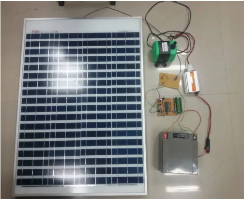
After the solar panels and other components were selected, the overall structural design of the of project made. The structure was prepared as shown in fig. 1.1. There is 100W polycrystalline solar panel, boost converter, PIC micro-controller, battery & pump motor.
All the accessories are assembled as shown in below figure 1.1
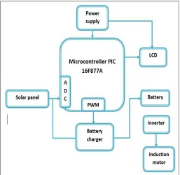
b. Electrical System
The overall mechanical and electrical subsystems were integrated into the solar power system as shown in Fig. 1.2 The detailed design of the circuitry could be found in the block diagram of the solar power system consists of mostly electrical components. This system consists of the PV cells, the charge controller and the lead-acid battery. Other subsystems such as the PIC microcontroller boost converter, battery. The PV cells absorb the sunrays and convert these into electricity. The electrical energy is then stored in the lead-acid battery that is later used to power the respective components.
Fig. 1.1: Solar powered battery charger & induction motor
connected to circuit as a source. The voltage will be monitored through PIC microcontroller using Analog to Digital channel. Corresponding voltage value will be display on the LCD interfaced with microcontroller. The same supply from solar panels will be given to 12 Volt batteries which are supplying power to inverter unit to give to induction motor. To give solar supply to battery, we have used boost converter. With the PWM of microcontroller, circuit is designed to boost solar voltage. We have used induction motor of 40W to be driven. To invert the battery supply into AC, we have used inverter circuit of 150W.
c. Modes of operation
There are three modes of operation of working the induction motor. They are namely: Fully solar power operated, Fully batery operated and partly solar & partly battery operated motor. In fully solar power operation mode, solar panel is placed directly in sunrays and in this mode the electricity generated directly from PV panel is used to drive motor through battery & inverter. In second mode of operation the battery is used to store the charge (electricity) in it using sunrays or battery can also be charged from electric supply. Using the energy stored in battery is then send to inverter which in turn drives the motor. Third mode the motor is run using partly solar power & partly battery voltage.
IV. PRINCIPLE OF MAXIMUM POWER POINT TRACKING CONTROL
The photovoltaic module operation de pends strongly on the load characteristics, (Fig. 2 and 3) to which it is connected. Indeed, for a load, with an internal resistance Ri, the optimal adaptation occurs only at one particular operating point, called Maximum Power Point (MPP) and noted in our case P max.
Thus, when a direct connection is carried out between the source and the load, (Fig. 1), the output of the PV module is seldom maximum and the operating point is not optimal.
To overcome this problem, it is necessary to add an adaptation device, MPPT controller with a DC-DC converter, between the source and the load, (Fig. 3). So, the MPPT controller is also required to track the new modified maximum power point in its corresponding curve.
V. FUZZY LOGIC MPPT CONTROLLER
Recently fuzzy logic controllers have been introduced in the tracking of the MPP in PV systems. They have the advantage to be robust and relatively simple to design as they do not require the knowledge of the exact model. They do require in the other hand the complete knowledge of the operation of the PV system by the designer.
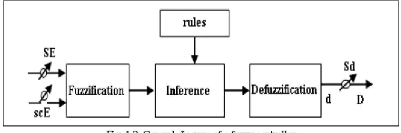
Fig. 1.3: General diagram of a fuzzy controller
The input E(k) shows if the load operation point at the instant k is located on the left or on the right of the maximum power point on the PV characteristic, while the input CE(k) expresses the moving direction of this point.
VI. RESULTS
a. Experimental Results
Table 5.1: Solar output of PV panel in fixed mode
Time of the day Voltage (V) Current (A) Power (W)
9 am 13.47 0.44 5.93
10 am 15.25 0.45 6.86
11 am 15.45 0.46 7.11
12 pm 16.11 0.51 8.22
1 pm 18.11 0.57 10.32
2 pm 16.23 0.53 8.60
3 pm 15.78 0.49 7.73
4 pm 13.32 0.43 5.73
5 pm 12.04 0.33 3.97
In order to validate the proposed modelling, it was necessary to compare the experiment results for the fixed panel. To obtain this data, simple experiments were performed. The setups were installed on building roof top. The open-circuit voltage and the current readings were recorded using a multi-meter connected to the solar cells. The readings are as shown in Table 5.1 and Table 5.2.
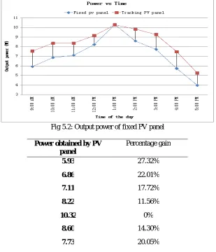
The graphical representation of current and power output of both the fixed PV panel and the tracking PV panel against day time is shown in fig. 5.1 and fig. 5.2. It illustrates improvement in efficiency gained with using solar tracking system.
From the graph, it can be seen that solar intensity increases with day time to maximum at 1pm and then starts decreasing. Some fluctuations notable in the graph were as a result of some cloudy sky and abnormal atmospheric condition. The percentage increase in solar power output gained is tabulated below.
The table 5.3 shows the percentage power increase that is obtained from PV panels. It is seen that at a point the power output of the fixed solar panel are ok. This is as a result of panel facing the sun.
Fig 5.2: Output power of fixed PV panel
Power obtained by PV panel
Percentage gain
5.93 27.32%
6.86 22.01%
7.11 17.72%
8.22 11.56%
10.32 0%
8.60 14.30%
7.73 20.05%
5.73 30.54%
3.97 32.24%
Table 5.3: Percentage increase gained
b. Simulation Results
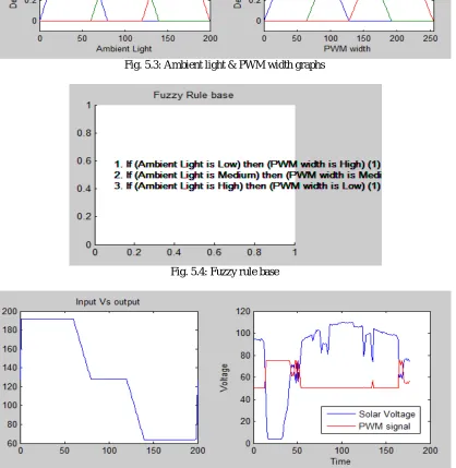
Fig. 5.3: Ambient light & PWM width graphs
Fig. 5.4: Fuzzy rule base
Fig. 5.5: Output of solar voltage Vs. PWM signal
The simulated current over the day was quite close to the actual results obtained. There was some slight deviation during the noon and evening period due to the modelling of the actual irradiance.
the fixed panel power to the sum of fixed panel power over the period of interest. The efficiency (obtain from experiment results) is around 20%. As compared to various the solar trackers as seen the average efficiency is around 12-15% and hence, the proposed design is slightly higher and comparable to the existing design.
VII. CONCLUSION
In this dissertation, MATLAB/SIMULINK model and hardware of an solar radiation system was developed.The microcontroller based circuit is used in this system with a minimum number of components to run the Pump Induction motor.
After examining the information obtained in the data table section and in plotted graph, It has been shown that the fixed panel system gives good eficiency using renewable energy sources. It can be said that the proposed system is a feasible method of maximizing the light energy received from sun. This is an efficient system for solar energy collection. The method implemented in this project is simple, easy to maintain and requires no technical attention for its operation. The software developed for this work can be used outside the mechanical part, thus it is flexible for future modification. The solar module gives good efficiency. Hence implementation of this technique in building solar systems will greatly improve utility satisfaction.The experimental results show a similar behavior in efficiency and the current output when compared them with the simulation results.
VIII. SCOPE FOR FUTURE WORK
To improve the flexibility, an automatic solar tracker system can be modelled with weather conditions such as wind and raindrop. Tracking the sun irradiance in an ideal condition would involve no disturbances on the system. But in practice, factors such as external force like wind and rain moves the tracker away from its position. It is therefore vital for the solar tracker to be able to track the sun throughout the daytime. The external disturbances such as wind loading and raindrop model provide an insight to the impact of the current consumption on the model of the solar tracker before actual implementation.
REFERENCES
1. Kroposki B, DeBlasio R, “Technologies for the New Millennium: Photovoltaics as a Distributed Resource”. IEEE Power Engineering Society Summer Meeting 2000: 1798 – 1801.
2. David Wettergreen, Benjamin Shamah, Paul Tompkins, William Whittaker “Robotic Planetary Exploration by Sun-Synchronous Navigation”,
6th International Symposium on Artificial Intelligence and Robotics & Automation in Space,i-SAIRAS 2001, Canadian Space Agency, St-Hubert, Quebec, Canada, June 18-22, 2001.
3. Md. Tanvir Arafat Khan, S.M. ShahrearTanzil, RifatRahman, S M ShafiulAlam, “Design and construction of an automatic solar tracking system”, 6th International Conference on Electrical and Computer Engineering ICECE 2010, 18-20 December 2010, Dhaka, Bangladesh.
4. C.Saravanan, Dr.M.A.Panneerselvam,I.William Christopher, “A Novel Low Cost Automatic Solar Tracking System”, International Journal of Computer Applications (0975 – 8887) Volume 31– No.9, October 2011.
5. Okan BINGOL, Ahmet ALTINTAS, Yusuf ONER, “Microcontroller based solar-tracking system and its implementation”, Journal of engineering sciences, 2005.
6. K. SreenivasaRao, M. Mahesh,“ARM Based Solar Tracking System”,International Journal of Modern Engineering Research (IJMER), Vol.2, Issue.4, July-Aug. 2012 pp-2504-2507.
7. Dr. Osama Gouda, Dr. GhadaAmer, Dr.TamerElkhodary, “Optimum Design and Implementation of Stand-alone Tracking Photovoltaic Power System based on PLC and Microcontroller”, Proceedings of the 14th International Middle East Power Systems Conference (MEPCON’10), Cairo University, Egypt, December 19-21, 2010, Paper ID 129.
8. M. A. Usta, Ö. Akyaz and İ. H. Altas, “Design and Performance of Solar Tracking System with Fuzzy Logic Controller”, 6th International Advanced Technologies Symposium (IATS’11), 16-18 May 2011, Elazığ, Turkey.
9. R. Kansal, and M. Singh, “PIC Based Automatic Solar Radiation Tracker”, Asian journal of chemistry Vol. 21, No. 10 ,2009.