Prediction and Correction Algorithm for a
Gesture Controlled Robotic Arm
Pushkar Shukla
1, Shehjar Safaya
2, Utkarsh Sharma
3B.Tech, College of Engineering Roorkee, Roorkee, India1 B.Tech, College of Engineering Roorkee, Roorkee, India2
B.Tech, National Institute of Technology Uttarakhand, Srinagar Garhwal, India3
ABSTRACT: One of the most popular technique to control robotic arm is by making it emulate the movements of the human arm. One of the advantages of the robotic arm is that it simplifies computational complexities. An arrangement of sensors attached to the human arm is used for tracking down hand movement. The arrangement consists of two accelerometers, a potentiometer and an IR receiver-transmitter pair. The Robotic Arm has Five degree of freedom where each joint is controlled by a servo motor that are capable of producing a movement of 180 degrees. In this paper we have proposed an algorithm based on correction and prediction for the purpose of swift synchronization of human hand and Robotic Arm. Successful implementation of the algorithm was achieved on the robotic arm.
KEYWORDS: Gesture recognition, Robotic arm, Human machine interface, gesture control.
I.INTRODUCTION
The design and control of a robotic arm involves many complexities that must be taken care of. Furthermore, making the robotic arm follow a given trajectory requires high precision and accuracy.Hence making the robotic arm copy the motion of the human hand not only provides greater precision but also gives great flexibility to the user. When gesture is the mode of control for a robot, characteristics of gestures are needed for designing and developing a gesture recognition system. [2]
A gesture is defined as a mode of non-verbal communication that involves the use of body parts such as fingers, wrists, head etc. A primary goal of gesture control is to create a system which can identify specific human gestures and use them to convey information. Several systems today are designed to utilize the features of gesture based interfaces like smart phones, ATM, computers and so on. After a gesture has been captured, there must exist a way or an algorithm for the gesture to be interpreted into meaningful command or instruction for the human-robot interaction [3].
Our paper deals with one such algorithm i.e. PREDICTION AND CORRECTION ALGORITHM FOR A GESTURE CONTROLLED ROBOTIC ARM which will emulate the movements of the human arm precisely.
II. LITERATURE REVIEW
Gesture recognition aims at the interpretation of human gestures via mathematical algorithms. Approaches to handle gesture recognition include complex mathematical models such as Hidden Markov Models, Artificial Neural Networks, Kalman Filtering and advanced Particle Filtering [1].
Gesture recognition enables humans to interact with machines naturally without the use of any external control devices. Using gestures to control a device makes it more convenient for the user, allowing him greater flexibility .The human machine interface (HMI) has a great use in areas of surgery and for day to day usage of physically handicapped people.
III. SETUP
A. SENSOR SETUP
This part of the setup needs to be worn on the human hand. The sensors consist of an Infra-Red transmitter receiver pair used for gripping. This sensor is just used to control the opening and closing of the end effector and therefore performs the action of a switch.2 MEMS accelerometer ADXL 335 are worn around the palm and the elbow and sense the movements of the human arm along these joints. The accelerometer that has been worn around the palm senses two different motions of the wrists. Apart from these sensors a potentiometer is used to track the rotation of the elbow in another direction.
Figure1. The complete setup including the robotic arm and the sensor setup that is worn around the human hand.
Figure 1 displays the various components that are attached to the robotic arm along with the robotic arm. All the sensors are clearly visible apart from the potentiometer that is worn on the other hand. Potentiometer was only used in order to economize the project. An IMU containing an integration of the accelerometer and the gyroscope can be used instead.
B. THE ROBOTIC ARM
Figure 2. The robotic arm (guroo) that has 5 degrees of freedom.
Figure 2 displays the various parts of the robotic arm .The arm overall combines a motion for gripping , 2 motions of the wrist and 2 movements of the elbow.
IV.APPROACH
An algorithm has been devised to make the robotic arm replicate the motions of the human arm .The robotic arm does not exactly have an idea of the exact movement of the human arm and takes input from noisy sensors. The algorithm is broken down into two parts. The job of the first section of the algorithm is to predict the present position for each joint with the aid of sensor data. The second part of the algorithm focuses on removing vibrations in the robotic arm that may occur due to small fluctuations in the sensor values.
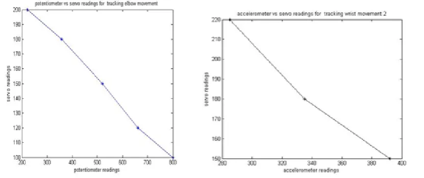
A. LINEAR PREDICTION
The values of the sensors and motors for every joint have been stored for certain predefined positions for each joint movement .The position of the robotic arm is predicted linearly using the given formulae. The position of the servo motor that lie between the predefined positions are predicted by the formula stated below:
𝑝𝑟𝑒𝑑𝑖𝑐𝑡𝑒𝑑 𝑠𝑒𝑟𝑣𝑜 𝑣𝑎𝑙𝑢𝑒 = 𝑚2 + 𝑚2 − 𝑚1 ∗ 𝑠2−𝑖𝑛𝑝𝑢𝑡 𝑠𝑒𝑛𝑠𝑜𝑟 𝑣𝑎𝑙𝑢𝑒
𝑠2−𝑠1 (1)
Figure 3.Linear prediction for wrist movement 1Figure4. Linear prediction for elbow movement 2
Figure5. Linear prediction for elbow movement 2Figure6. Linear prediction for wrist movement 2
Figure 2 displays the linear plot that has been drawn with the help of predefined values for movement 1. The plot is drawn on the basis of the accelerometer values and servo values for 5 different positions during movement 1. Figure 3 displays linear plot drawn on the basis of 5 different positions during movement 2. We have used a potentiometer that is attached at the lower end of the elbow. The potentiometer and servo readings are recorded for different positions and a graph is plotted with the help of these values. Similarly figure 1 and figure 4 display the two plots for that predict the values of the wrist movement.
B. CORRECTION
We observed that the robotic arm may still vibrate even if the human hand is still. Therefore, there is a strong need to remove these vibrations .Also the robotic arm must be able to capture small movements. The correction part of the algorithm focuses on removing the small vibration in a robotic arm due to the noisy sensors. The predicted value is compared to the present value of the servo motor and the difference between the two values is noted down
𝑒𝑟𝑟𝑜𝑟 = 𝑝𝑟𝑒𝑑𝑖𝑐𝑡𝑒𝑑 𝑣𝑎𝑙𝑢𝑒 − 𝑝𝑟𝑒𝑠𝑒𝑛𝑡 𝑣𝑎𝑙𝑢𝑒
(2)
𝑝𝑟𝑒𝑠𝑒𝑛𝑡 𝑣𝑎𝑙𝑢𝑒 = 𝑝𝑟𝑒𝑠𝑒𝑛𝑡 𝑣𝑎𝑙𝑢𝑒 + 𝑒𝑟𝑟𝑜𝑟 , 𝑒𝑟𝑟𝑜𝑟 ≥ 𝑡ℎ𝑟𝑒𝑠ℎ𝑜𝑙𝑑
𝑝𝑟𝑒𝑠𝑒𝑛𝑡 𝑣𝑎𝑙𝑢𝑒, 𝑒𝑟𝑟𝑜𝑟 < 𝑡ℎ𝑟𝑒𝑠ℎ𝑜𝑙𝑑 (3)
V. RESULT
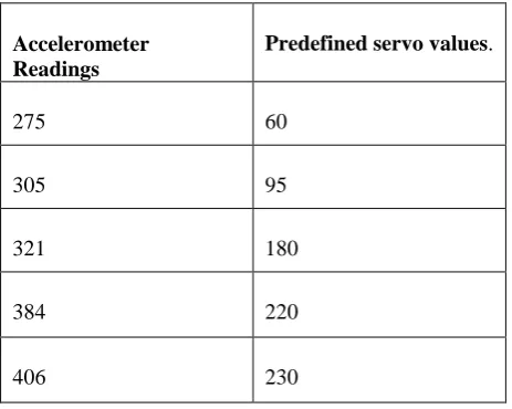
As the error can be both positive and negative hence the robotic arm becomes less susceptible to vibrations as when the human arm vibrates the error would eventually cancel itself or become small in magnitude than the threshold value and at the same time it can detect small changes made in the human arm because the error adds up to cross the threshold. We now demonstrate our algorithm for a single servo –accelerometer pair.
Accelerometer Readings
Predefined servo values.
275 60
305 95
321 180
384 220
406 230
Table 1: The predefined accelerometer servo values for a movement.
Now let us assume that our accelerometer gives a reading of 315, that lies between 305 and 321.The corresponding servo value is calculated with the help of equation 1 where, m1= 95,m2=180,s1=305,s2=321. On substituting these values in the equation the servo value that is predicted is 148.125 that can be rounded up to 148. So the predicted value now becomes 148. Now the error between the predicted value and the present value is calculated. We assume two different scenarios here .In scenario 1 when the magnitude of the difference between the present value and the predicted value is less than a threshold value say 8, the motor assumes the present value according to equation 3 .Let us say that the value present value of the motor is 150, so the error will be -2 this case having a magnitude less than the threshold .Therefore there will be no change in the predicted value and the new servo value will remain 148. On the contrary, if the present value was 130 and the predicted value is 148, the difference between these values is greater than the threshold 8.So the present value will be updated to 148.
During the initial phase of the construction of the algorithm to control the robotic arm emphasis was laid only on the prediction part .The correction part was later introduced in order to overcome the disturbances that are present in the robotic arm due to noise present in the sensors. The correction part of the algorithm ensures a smooth control for the robotic arm that overcomes hiccups that vibrations occurring in the arm.
VI.CONCLUSION AND FUTURE PROSPECTS
VII.APPENDIX
A. M2- predefined value of the servo motor for the next known position. B. M1- predefined value of the servo motor for the previous known position C. S1- predefined sensor value for the last known position
D. S2- predefined sensor value for the next known position
REFERENCES
[1] Pavlovic, V. Sharma, R. & Huang, T. (1997), "Visual interpretation of hand gestures for human- computer Interaction: A review" (IEEE Trans. Pattern Analysis and Machine Intelligence, Vol. 19(7), pp. 677 -695, July, 1997.
[2] R. Chen et al., “Toward Secure Distributed Spectrum Sensing in Cognitive Radio Networks,” IEEE Commun. Mag., vol. 46,pp. 50–55, Apr. 2008.
[3] Wong Guan Hao, Yap Yee Leck and Lim Chot Hun,“6-DOFPC-Based robotic arm (PC-robo arm) with efficient trajectory planning and speed control” 2011 4th International Conference on Mechatronics (ICOM), 17-19 May 2011.
[4] Chung-Hsien Kuo, Yu-Wei Lai, Kuo-Wei Chiu, Shih-Tseng Lee. “Motion Planning and Control of Interactive Humanoid Robotic Arms” IEEE International Conference on Advanced Robotics and its Social Impacts Aug. 23-25, 2008.
BIOGRAPHY
A. PUSHKAR SHUKLA
PUSHKAR SHUKLA is an Electronics and Telecommunications Engineer who graduated from College of engineering Roorkee in the year 2014. He is a robotics enthusiasts and loves making robots. Apart from robotics he is highly interested in machine learning, probabilistic models, human machine interfaces, embedded systems and image processing.
B. SHEHJAR SAFAYA
SHEHJAR SAFAYA is an Electronics and Telecommunications engineer and has a high affinity for VLSI and chip fabrication. He wants to become a VLSI professional in the future. He completed his graduation in the year 2014 from College of Engineering Roorkee.
C. UTKARSH SHARMA