Scholarship@Western
Scholarship@Western
Electronic Thesis and Dissertation Repository
6-21-2012 12:00 AM
Performance of Hollow Bar Micropiles Under Axial and Lateral
Performance of Hollow Bar Micropiles Under Axial and Lateral
Loads in Cohesive Soils
Loads in Cohesive Soils
Ahmed Yehia Abd El-aziz The University of Western Ontario
Supervisor
M. Hesham El Naggar
The University of Western Ontario
Graduate Program in Civil and Environmental Engineering
A thesis submitted in partial fulfillment of the requirements for the degree in Doctor of Philosophy
© Ahmed Yehia Abd El-aziz 2012
Follow this and additional works at: https://ir.lib.uwo.ca/etd
Part of the Geotechnical Engineering Commons
Recommended Citation Recommended Citation
Abd El-aziz, Ahmed Yehia, "Performance of Hollow Bar Micropiles Under Axial and Lateral Loads in Cohesive Soils" (2012). Electronic Thesis and Dissertation Repository. 595.
https://ir.lib.uwo.ca/etd/595
This Dissertation/Thesis is brought to you for free and open access by Scholarship@Western. It has been accepted for inclusion in Electronic Thesis and Dissertation Repository by an authorized administrator of
PERFORMANCE OF HOLLOW BAR MICROPILES UNDER AXIAL AND LATERAL LOADS IN COHESIVE SOILS
(Spine title: Performance of hollow bar micropiles under different loads) (Thesis format: Monograph)
by
Ahmed Yehia Abd Elaziz
Graduate Program in Engineering Science
Department of Civil and Environmental Engineering
A thesis submitted in partial fulfillment of the requirements for the degree of
Doctor of Philosophy
The School of Graduate and Postdoctoral Studies The University of Western Ontario
London, Ontario, Canada
ii
THE UNIVERSITY OF WESTERN ONTARIO School of Graduate and Postdoctoral Studies
CERTIFICATE OF EXAMINATION
Supervisor
______________________________ Dr. M. Hesham El Naggar
Supervisory Committee
______________________________ Dr. Maged Youssef
______________________________ Dr.
Examiners
______________________________ Dr. Tim Newson
______________________________ Dr. Abouzar Sadrekarimi
______________________________ Dr. Pawel Kurowski
______________________________ Dr. Dennis Becker
The thesis by
Ahmed Yehia Abd Elaziz
Entitled:
Performance of hollow bar micropiles under axial and lateral
loads in cohesive soils
is accepted in partial fulfillment of the requirements for the degree of
Doctor of Philosophy
iii
ABSTRACT
The use of hollow core bars in micropiles has greatly increased over the past ten years.
Hollow core construction, also known as “self drilled”, is becoming a popular option
because it allows a faster installation processes and ground improvement at the same
time. Despite the growing demand for hollow bar micropiles, little work has been
devoted to evaluating the nominal bond strength between the micropile grout and the
surrounding soil, especially in clayey soils. Moreover, the performance of such
micropiles under different kinds of loading is still largely unknown and needs to be
investigated.
In this study, a research methodology encompassing two primary elements is adopted.
The first element is a series of full scale field studies on hollow bar micropiles installed in
cohesive soils, while the second is numerical investigations on hollow bar micropiles. To
accomplish the study, four hollow core micropiles were installed using an air flushing
technique employing large drilling carbide bits. Twenty-two load tests were conducted on
the four hollow bar micropiles. The hollow bar micropiles were loaded in four
consecutive phases, which included; five axial monotonic, five axial cyclic load tests on
single micropiles, four axial monotonic tests on pairs of hollow bar micropiles, two
monotonic and six cyclic lateral tests on single micropiles. The results of each set of tests
were utilized to validate a numerical model. Parametric studies were conducted on the
calibrated model to provide design guide lines for hollow bar micropiles under different
iv
An equation is proposed to estimate the axial capacity of hollow bar micropiles in
cohesive soils depending on the installation method adopted. In addition, an equation for
the stiffness degradation under axial cyclic loading is proposed. It reveals that the group
efficiency factor for hollow bar micropiles should be taken equal to 1, despite the spacing
to diameter ratio employed. Moreover, a family of interaction factor diagrams is
established to estimate the settlement of hollow bar micropiles group. Finally, the study
demonstrated that hollow bar micropiles can carry moderate lateral loads with proper
reinforcement configurations and pile head fixity condition.
Keywords
v
CO-AUTHORSHIP STATEMENT
This thesis is prepared in accordance with the regulation for a monograph format thesis
stipulated by the school of graduate and post graduate studies at Western University. Dr.
M. Hesham El Naggar, the author supervisor, is co-author of all the work presented in
this thesis. The results of the field tests presented in chapter five are published in three
vi
ACKNOWLEDGMENTS
The author wishes to express his deep gratitude to Dr. M. Hesham El Naggar for his
supervision, encouragement, and never ending contribution and guidance during the
process of this work. I am thankful to him for giving me this opportunity to work in his
research team which expanded my geotechnical knowledge. Dr. El Naggar facilitated for
me so many resources for finishing this project.
I would also like to express my appreciation to Williams Form Hard Ware for funding
support through the course of the field tests. Special thanks to Mr. Martin Hodgson from
Williams for his technical support throughout the research project. Sincere appreciations
for EBS Engineering and Construction Company for installing the micropiles and for
help setting the reaction frame at no cost. In addition, I want to thank BASF the chemical
company for providing the 1341 Master flow grout at no cost.
The genuine assistance from the staff of the Geotechnical Research Centre, (GRC) and
the University Machine Services (UMS) is acknowledged. Furthermore, I want to thank
Wilbert Logan, Western Engineering labs supervisor, for his suggestions and assisting
during piles instrumentation and Melody Richards, geotechnical lab supervisor, for
helping during the laboratory tests of the soil samples.
I want to express very deep thanks to all graduate students who assisted me during my
PhD studies, provided me with insight suggestions and their friendship that kept me
vii
No words can describe my thanks, gratitude and appreciation to my wife, Radwa; the
candle that was burning herself to shed light on my path during both stressful and
pleasant moments. Her patience, encouragement and love were peerless. I like to thank
my son Kareem for being the source of great joy that kept my life in balance. Finally, the
author wishes to express his sincere thanks to his father and mother for their endless love
viii
Table of Contents
Page
CERTIFICATE OF EXAMINATION ………...………... ii
ABSTRACT ………... iii
CO-AUTHORSHIP STATEMENT ………... v
ACKNOWLEDGMENTS ………. vi
Table of Contents ………... viii
List of Tables ………. xiv
List of Figures ……… xviii
List of Symbols ………. xxix
List of Appendices ………. xxxvii
CHAPTER 1: INTRODUCTION ……….. 1
1.1 Overview ……… 1
1.2 Historical Background ………... 2
1.3 Research Objectives ………... 5
1.4 Research Methodology ……….. 6
1.5 Organization of the Dissertation ……… 7
CHAPTER 2: LITERATURE REVIEW ……….. 9
ix
2.2 Micropiles Classification ……….. 10
2.2.1 Design classification of micropiles ………... 11
2.2.2 Construction classification of micropiles ………. 11
2.2.3 Classification of hollow-bar micropiles ………... 15
2.3 Design Considerations for Micropiles ……….. 16
2.3.1 Structural design of micropiles ……….. 17
2.3.2 Geotechnical design capacity of micropiles ……….. 19
2.3.3 Design consideration of hollow bar micropiles ………. 20
2.4 Review of Previous Studies ………... 21
2.4.1 Investigations of different types of micropiles ……….. 23
2.4.2 Previous work on hollow bar micropiles ……….. 32
CHAPTER 3: SOIL INVESTIGATION AND GROUT EVALUATION ……… 36
3.1 Soil Investigation ………... 36
3.1.1 Site location and description ………. 36
3.1.2 Site investigation program ………. 36
3.1.3 Standard penetration test equipment and procedure ………... 37
3.2 Subsurface Conditions ……….. 40
3.2.1 Soil stratigraphy ……… 40
x
3.2.3 Soil shear strength parameters ………... 50
3.2.4 Soil stress history ………... 60
3.2.5 Soil stiffness parameter ………. 64
3.3 Grout Testing and Evolution ………. 67
CHAPTER 4: HOLLOW CORE MICROPILE MATERIAL AND INSTALLATION ………... 69
4.1 Hollow Core Steel Bar and Accessories ……… 69
4.2 Hollow Bar Micropile Installation ………. 77
4.2.1 Preparing the drilling rig ………... 80
4.2.2 Installation and grouting ……… 83
4.3 Embedded Strain Gauges Instrumentation ………. 88
CHAPTER 5: AXIAL MONOTONIC AND CYCLIC PERFORMANCE OF HOLLOW BAR MICROPILES ……… 91
5.1 Introduction ……… 91
5.2 Axial Monotonic Load Tests ………. 92
5.2.1 Testing equipment ………. 92
5.2.2 Pile head instrumentation ……….. 95
5.2.3 Monotonic load test procedure ……….. 97
5.2.4 Monotonic test results and analysis ………... 99
xi
5.3.1 Test equipment and instrumentation ……… 106
5.3.2 Cyclic load test procedure ………. 106
5.3.3 Cyclic load test results and analysis ……….. 107
5.4 Numerical Analysis ……… 118
5.5 Axial Loading Numerical Models ………. 119
5.5.1 Monotonic axial loading models ………... 120
5.5.2 Calibration of the monotonic field test results ……….. 135
5.5.3 Failure criteria ……….. 147
5.5.4 Load transfer mechanism ……….. 152
5.5.5 Parametric study ……… 158
5.5.6 Closed form solution for hollow bar micropiles embedded in clayey soils under monotonic loading ………. 177
5.5.7 Cyclic axial model ………. 178
5.5.8 Calibration of the cyclic field test ……….. 181
CHAPTER 6: HOLLOW BAR MICROPILES GROUP BEHAVIOR …………. 188
6.1 Introduction ……… 188
6.2 Field Pile Group Load Tests ……….. 188
6.2.1 Testing equipment ………. 188
6.2.2 Pile head instrumentation ……….. 191
xii
6.2.4 Pile group test results and analysis ……… 197
6.3 Numerical Analysis ……… 202
6.3.1 Geometric modeling ……….. 203
6.3.2 Material modeling ………. 208
6.4 Calibration of Pile Group Field Tests ……… 209
6.4.1 Micropile group capacity ………... 211
6.5 Parametric Study ……… 215
6.5.1 Parametric study for group capacity ……….. 215
6.5.2 Parametric study for group performance ………... 220
CHAPTER 7: LATERAL MONOTONIC AND CYCLIC PERFORMANCE OF HOLLOW BAR MICROPILES ……… 234
7.1 Introduction ……… 234
7.2 Monotonic Lateral Load tests ……… 234
7.2.1 Lateral load testing equipment and pile head instrumentation …….. 235
7.2.2 Lateral monotonic load test procedure and results ……… 238
7.2.3 Failure mechanism and ultimate capacity for micropiles under lateral loads ………... 240
7.2.4 Numerical simulation of monotonic lateral load tests ………... 244
7.2.5 Calibration of the monotonic lateral field test ………... 248
xiii
7.3 Lateral Cyclic Load Tests ……….. 266
7.3.1 Lateral cyclic load test procedure ……….. 267
7.3.2 Cyclic load test results and analysis ……….. 268
CHAPTER 8: SUMMARY, CONCLUSIONS, AND RECOMMENDATIONS 281 8.1 Summary ……… 281
8.2 Results and Conclusions ……… 283
8.2.1 Axial capacity of hollow bar micropile ………. 283
8.2.2 Lateral performance of hollow bar micropiles ……….. 284
8.2.3 Hollow bar micropile group behavior ………... 286
8.3 Recommendations for future work ……… 287
REFERENCES ……….. 289
APPENDIX A: COPYRIGHT PERMISSIONS ……….... 298
xiv
List of Tables
Description Page
Table 2.1. Typical αbond (Grout-to-Ground Bond) Values for Micropile Design (after FHWA NHI 2005) ………..
22
Table 3.1. Index properties of the silty clay layer ………. 46
Table 3.2. Soil properties for samples extracted from BH-2 ……… 47
Table 3.3. Summary of (UU) triaxial tests on samples from BH2 ……… 52
Table 3.4. Undrained shear strength values for the cohesive deposit …………... 55
Table 3.5. Computed angle of friction from SPT values for BH-1 ……….. 58
Table 3.6. Computed angle of friction from SPT values for BH-2 ……….. 58
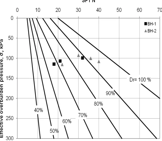
Table 3.7. Relative density and friction angle for BH-1 ……….. 58
Table 3.8. Relative density and friction angle for BH-2 ……….. 59
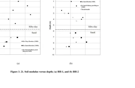
Table 3.9. Average values of ko ……….. 62
Table 3.10. Summary of grout strength ……… 68
Table 4.1. B7X Geo-drill bars (Ground Anchor System 2011) ……… 71
Table 4.2. Types of lost bits and the applicable type of soil for each one (Ground Anchor System 2011) ……… 74 Table 4.3. Types and the available drill bit diameters ……….. 75
Table 4.4. Strain gauge properties ……… 90
xv
Table 5.2. Summary of the monotonic testes phase results ……….. 105
Table 5.3. Design, amplitude and maximum applied load for cyclic load tests… 107
Table 5.4. Percentage increase in pile head displacement at the end of cyclic loading ………..
115
Table 5.5. Initial and final stiffness of all the micropiles after the cyclic load test
………...
115
Table 5.6. Geotechnical parameters assigned to the Mohr-Coulomb model …… 127
Table 5.7. Summary of the mesh sensitivity analysis parameter used ………….. 145
Table 5.8. Most common failure criteria for micropiles ………... 149
Table 5.9. Failure loads for Micropiles in compression ………... 150
Table 5.10 Compression capacity of hollow bar micropile, L = 5.75m, L /d =30,
dE = 1.25d ………...
162
Table 5.11. Compression capacity of hollow bar micropile, L = 5.75m, L /d
=30, dE = 1.5d ………
162
Table 5.12. Compression capacity of hollow bar micropile, L = 5.75m, L /d
=30, dE = 1.75d ………...
163
Table 5.13. Compression capacity of hollow bar micropile, L = 5.75m, L /d
=30, dE = 1.75d ………...
163
Table 5.14. Compression capacity of hollow bar micropile, L = 5.75m, L /d
=30, dE = 2d ………
164
Table 5.15. Compression capacity of hollow bar micropile, L = 8.8m, L /d =50,
dE = 1.25d ………...
164
Table 5.16. Compression capacity of hollow bar micropile, L = 8.8m, L /d =50,
dE = 1.5d ……….
xvi
Table 5.17. Compression capacity of hollow bar micropile, L = 8.8m, L /d =50,
dE = 1.75d ………...
165
Table 5.18. Compression capacity of hollow bar micropile, L = 8.8m, L /d =50,
dE = 1.75d ………...
166
Table 5.19. Compression capacity of hollow bar micropile, L = 8.8m, L /d =50,
dE = 2d ………
166
Table 5.20. Uplift capacity of hollow bar micropile, L = 5.75m, L /d =30, dE =
1.25d ………...
167
Table 5.21. Uplift capacity of hollow bar micropile, L = 5.75m, L /d =30, dE =
1.5d ……….
167
Table 5.22. Uplift capacities of hollow bar micropile, L = 5.75m, L /d =30, dE =
1.75d ………...
168
Table 5.23. Uplift capacity of hollow bar micropile, L = 5.75m, L /d =30, dE =
1.75d ………...
168
Table 5.24. Uplift capacity of hollow bar micropile, L = 5.75m, L /d =30, dE =
2d ………
169
Table 5.25. Uplift capacity of hollow bar micropile, L = 8.8m, L /d =50, dE =
1.25d ………...
169
Table 5.26. Uplift capacity of hollow bar micropile, L = 8.8m, L /d =50, dE =
1.5d ……….
170
Table 5.27. Uplift capacity of hollow bar micropile, L = 8.8m, L /d =50, dE =
1.75d ………...
170
Table 5 28. Uplift capacity of hollow bar micropile, L = 8.8m, L /d =50, dE =
1.75d ………...
171
Table 5.29. Uplift capacity of hollow bar micropile, L = 8.8m, L /d =50, dE =
2d ………
171
xvii
Table 6.2. Pile group stiffness ……….. 202
Table 6.3. Number of elements for each model ……… 205
Table 6.4. Group efficiency factor abased on pile spacing ……… 212
Table7.1. Lateral interpretation criteria for piles ……….. 243
Table7.2. Interpreted failure load for MP1 and MP2 ……… 243
Table7.3. Grout and steel properties adopted in material modeling ………. 250
Table7.4. Values of ε50 for stiff clay model in LPile (after Isenhower and Wang
2011) ……….
xviii
List of Figures
Description Page
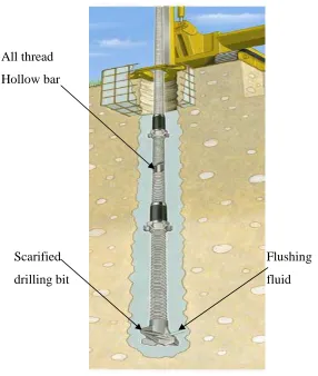
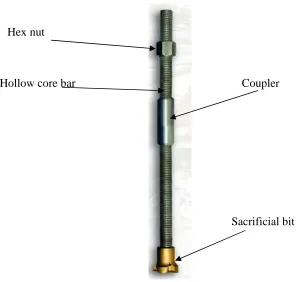
Figure 1.1. Hollow bar micropiles system components (after micropiles
brochures- Con-Tec system Ltd. 2011) ………... 4
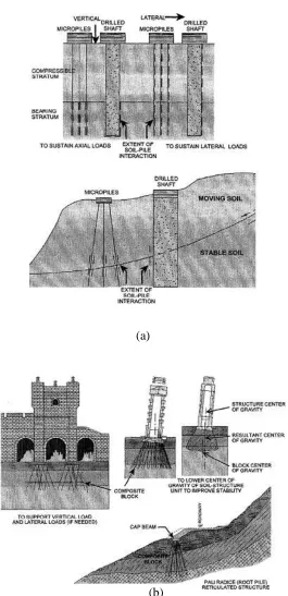
Figure 2.1. Micropile classification system based on philosophy of behavior (after FHWA 2000) (a) Case 1 (b) Case 2 ………... 12
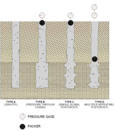
Figure 2.2. Micropile classification system based on method of grouting (after FHWA 2000) ………. 14
Figure 2.3. Final hollow core micropile (after Con-Tec system Ltd. 2011) ………. 16
Figure 3.1. Location of test site (Google Map) ………. 37
Figure 3.2. Plan view for the layout of Site 1 and Site 2 ……….. 38
Figure 3.3. The Mounted (Morocka ) rig and the solid stem used ……… 39
Figure 3.4. Steps during field exploration ………. 39
Figure 3.5. Borehole log for Site 2 (Livneh 2006) ……… 41
Figure 3.6. The borehole log and the SPT (Nfield) values versus depth for BH-1 …. 42 Figure 3.7. The borehole log and the SPT (Nfield) values versus depth for BH-2 …. 43 Figure 3.8. Soil stratigraphy ……….. 44
Figure 3 9. Piece of the soil at the top 1 m from the test site ……… 44
Figure 3.10. Index properties with respect to Plasticity chart ………... 47
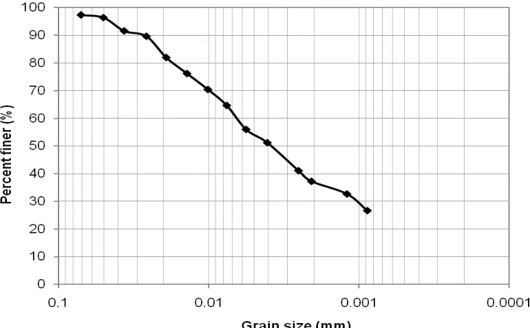
Figure 3.11. Hydrometer Grain size distribution of sample from BH-1 at depth 1.5m ……… 48
xix
Figure 3.13. Grain Size distribution of sample from BH-2 at depth 5.8m ………… 49
Figure 3.14. Grain Size distribution of sample from BH-1 at depth 7 ……….. 49
Figure 3.15. Triaxial test result for sample at depth 3.0 m, BH-2 ……… 51
Figure 3.16. Triaxial test result for sample at depth 3.7 m, BH-2 ……… 51
Figure 3.17. Triaxial test result for sample at depth 4.3 m, BH-2 ……… 52
Figure 3.18. su profile versus depth; (a) BH-1; and (b) BH-2 ……….. 56
Figure 3.19. Relative density-Nfield relation based on Holtz and Gibbs (1979) …… 59
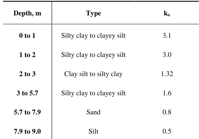
Figure 3.20. OCR profile for (a) BH-1; and (b) BH-2……….. 63
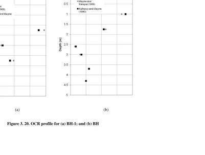
Figure 3.21. Soil modulus versus depth; (a) BH-1, and (b) BH-2 ……… 66
Figure 4.1. Hollow core bar micropile parts (after Ground Anchor System 2011)... 70
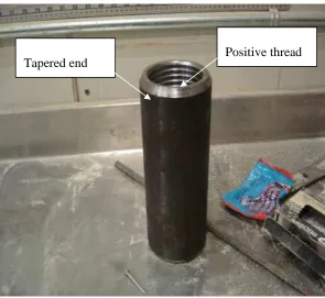
Figure 4.2. B7X2-76 coupler ……… 73
Figure 4.3. Three new large bits; (a) Tungsten carbide cross bit (d= 176mm); (b) Double cross bit (d = 176 mm), and (c) Carbide button cross drill bit (d= 225 mm) ……….. 76
Figure 4.4. Hot dip galvanized centralizer (after Ground Anchor System 2011) …. 76 Figure 4.5. Installation process of hollow core micropile (after Ground Anchor System 2011) ……….. 78
Figure 4.6. B7X1-76 Geo-drilled hollow core bars ……….. 80
Figure 4.7. TE 550 hydraulic drifter mounted on an excavator ……… 81
Figure 4.8. All possible connections between the drafter hammer and the hollow bar (after Ground Anchor System 2011) ……… 82
xx
Figure 4.10. Water delivered out of the drilling bit ……….. 85
Figure 4.11. The broken double cross bit ……….. 85
Figure 4.12. Type XAS 375 JD6 portable air compressor ……… 87
Figure 4.13. Colloidal mixer grout plant ……….. 87
Figure 4.14. A group of four micropiles ………... 88
Figure 4.15. EM-5 strain gauge parts and dimensions ……….. 90
Figure 5.1. Cross-section and dimensions of main loading beam (dimension are in mm) ……… 93
Figure 5.2. Reaction frame used during monotonic and cyclic loading …………... 94
Figure 5.3. Location of tested and position of reaction piles ……… 95
Figure 5.4. Micropile head instrumentation during compression tests ………. 97
Figure 5.5. Micropile head instrumentation during tension tests ……….. 98
Figure 5.6. Load-displacement curves for three monotonic compression tests …… 102
Figure 5.7. Load-displacement curves for two monotonic tension tests ………….. 102
Figure 5.8. Load and displacement versus time of the cyclic compression tests on MP1 ……… 109
Figure 5.9. Load and displacement versus time of the cyclic compression tests on MP2 ……… 109
Figure 5.10. Load and displacement versus time of the cyclic compression tests on MP3 ……… 110
xxi
Figure 5.12. Load and displacement versus time of the tension cyclic load test on
MP4 ……… 111
Figure 5.13. Load – displacement curves for the compression cyclic test on MP1... 111
Figure 5.14. Load -displacement curves for the tension cyclic test on MP4 ……… 112
Figure 5.15. Accumulation of displacement for 15 cycles of loading and
unloading ……… 114
Figure 5.16. Pile head stiffness versus number of cycles for compression cyclic
tests on MP1 ………... 116
Figure 5.17. Pile head stiffness versus number of cycles for compression cyclic
tests on MP2 ………... 116
Figure 5.18. Pile head stiffness versus number of cycles for compression cyclic
tests on MP3 ………... 117
Figure 5.19. Pile head stiffness versus number of cycles for compression cyclic
tests on MP4 ………... 117
Figure 5.20. Pile head stiffness versus number of cycles for tension cyclic tests on
MP4 ……… 118
Figure 5.21. Axisymmetric geometry model ……… 122
Figure 5.22. CAX4 bilinear element with four integration points ……… 122
Figure 5.23. The geometry of the axisymmetric model and the boundary
conditions ………... 123
Figure 5.24. Meshing techniques on two models: (a) coarse mesh; (b) fine mesh… 124
Figure 5.25. Tri-linear stress-strain relation used to model the grout material ……. 125
Figure 5.26. Default pressure ‒ overclosure relationship ………. 128
Figure 5.27. Slip regions for the friction model with a limit on the critical shear
xxii
Figure 5.28. Elastic slip versus shear traction relationship for sticking and slipping
friction ……… 132
Figure 5.29. Step and total time for a simulation ……….. 134
Figure 5.30. The proposed micropile geometry ……… 136
Figure 5.31. Flow chart of the methodology used to evaluate dE and LE …………. 138
Figure 5.32. Calibration of MP1 in compression ……….. 139
Figure 5.33. Calibration of MP3 in compression ……….. 140
Figure 5.34. Calibration of MP2 in compression ……….. 140
Figure 5.35. Field test results and hyperbolic function of MP1 in compression ….. 142
Figure 5.36. Extended field results and FE model for MP1 in compression ……… 142
Figure 5.37. Calibration of MP2 in tension ……….. 143
Figure 5.38. Calibration of MP4 in tension ……….. 143
Figure 5.39. Effect of horizontal boundary in Mesh_1 ………. 145
Figure 5.40. Effect of number of elements on the micropile capacity, 10m model,
α =0.9 ………. 146
Figure 5.41. Effect of number of elements on the micropile capacity, 12m model,
α =0.9 ………. 147
Figure 5.42. Failure load MP1 compression ………. 151
Figure 5.43. Failure Loads MP2 in compression ……….. 151
Figure 5.44. Failure load MP3 Compression ……… 152
xxiii
Figure 5 46. Load transfer for MP2 Compression ……… 154
Figure 5.47. Load transfer for MP3 in compression ………. 155
Figure 5.48. Shear stress along the micropile at failure loads ……….. 157
Figure 5.49. Example of failure load obtained at su = 150kPa, α =1.0, L/d =30 ….. 161
Figure 5.50. Load distribution obtained from at QF = 614 kN, su = 150kPa, α =1.0,
L/d =30 ………... 161
Figure 5.51. The relation between percentage of the increase in the hole volume
and the normalized shaft resistance under compression, L/d=30 …….. 174
Figure 5.52. The relation between percentage of the increase in the hole volume
and the normalized shaft resistance under compression, L/d=50 …….. 174
Figure 5.53. The relation between percentage of the increase in the hole volume
and the normalized shaft resistance under compression ……… 175
Figure 5.54. The relation between percentage of the increase in the hole volume
and the normalized shaft resistance under tension, L/d=30 …………... 175
Figure 5.55. The relation between percentage of the increase in the hole volume
and the normalized shaft resistance under tension, L/d=50 …………... 176
Figure 5.56. The relation between percentage of the increase in the hole volume
and the normalized shaft resistance under tension ………. 176
Figure 5.57. Applying the temperature field and the degradation in soil shear
modulus during calibration of cyclic field test ………... 181
Figure 5.58. Load-displacement calibration of cyclic test on MP1 ……….. 183
Figure 5.59. Load-displacement calibration of cyclic test on MP2 ……….. 183
Figure 5.60. Load-displacement calibration of cyclic test on MP3 ……….. 184
xxiv
Figure 5.62. Variation of stiffness due to cyclic loading for MP1 ……….... 185
Figure 5.63. Variation of stiffness due to cyclic loading for MP2 ……….... 186
Figure 5.64. Variation of stiffness due to cyclic loading for MP3 ……….... 186
Figure 5.65. Variation of stiffness due to cyclic loading for MP4 ………
187
Figure 6.1. Plane view of loading plate, all dimensions are in mm ……….. 190
Figure 6.2. Details of the hollow bar micropile’s head connection ……….. 190
Figure 6.3. Pile group assembly ……… 192
Figure 6.4. Positioned the lower beam above the load instrumentations ………….. 192
Figure 6.5. Centering and leveling the upper beam over the lower one …………... 193
Figure 6. 6. Final pile group setup ……… 193
Figure 6.7. Arrangements of the instruments at the top of the steel pile raft ……… 195
Figure 6.8. Center to center spacing of the tested micropiles ………... 196
Figure 6.9. Load-displacement curves for PG1 and MP1 ………. 198
Figure 6.10. Load-displacement curves for PG2, MP2 and MP3 ………. 199
Figure 6.11. Load-displacement curves for PG3, MP1 and MP2 ………. 199
Figure 6.12. Load-displacement curves for PG4 and MP3 ……….. 200
Figure 6.13. Load-displacement curve for all field pile group tests ………. 200
Figure 6.14. Axes of symmetry in micropile group assembly ……….. 205
xxv
Figure 6.16. The 3D quarter shape model of the soil ……… 206
Figure 6.17. The 3D circular shape of the soil ……….. 206
Figure 6.18. The geometric model of the micropile in the group analysis ………... 207
Figure 6.19. Effect of model shape and vertical boundary on model behavior …… 207
Figure 6.20. Load – displacement of field test and its FE calibration: (a) PG1; (b)
PG2; (c) PG3; and (d) PG4 ……… 210
Figure 6.21. Capacity of pile group at group efficiency equal to 1.0: (a) PG1; (b)
PG2; (c) PG3; and (d) PG4 ……… 214
Figure 6.22. Load – group displacement for su= 90 kPa and L/d =30 ……….. 218
Figure 6.23. Load – group displacement for su= 175 kPa and L/d = 30 …………... 218
Figure 6.24. Load – group displacement for su= 100 kPa and L/d = 50 ………….. 219
Figure 6.25. Load – group displacement for su= 175 kPa and L/d = 50 ………….. 219
Figure 6.26. Load – group displacement for su= 50 kPa and L/d =30 ……….. 220
Figure 6.27. Geometric model adopted for interaction calculations ………. 224
Figure 6.28. Interaction factors at the design load for L/d=30 ………. 225
Figure 6.29. Interaction factors at the design load for L/d =50 ……… 226
Figure 6.30. Interaction factors at the design load for L/d=75 ………... 226
Figure 6.31. Influence of L/d on the interaction factor between hollow bar
micropiles , Ep/Es =1000………... 227
Figure 6.32. Influence of L/d on the interaction factor between hollow bar
micropiles , Ep/Es =1000………... 227
xxvi
Figure 6.34. Effect of intermediate hollow bar micropile on the interaction factor,
S/dhole =7.5, L/d =30 ………...
229
Figure 6.35. Effect of intermediate hollow bar micropile on the interaction factor,
S/dhole =10, L/d =30 ……… 231
Figure 6.36. Effect of intermediate hollow bar micropile on the interaction factor,
S/dhole =15, L/d =30 ……….... 231
Figure 6.37. Effect of intermediate hollow bar micropile on the interaction factor,
S/dhole =7.5, L/d =50 ………... 232
Figure 6.38. Effect of intermediate hollow bar micropile on the interaction factor,
S/dhole =10, L/d =50 ………
232
Figure 6.39. Effect of intermediate hollow bar micropile on the interaction factor,
S/dhole =15, L/d =50 ………
233
Figure 7.1. Lateral load test setup ………. 236
Figure 7.2. Work shop drawing for the three main plates ………. 237
Figure 7.3. Position of the applied load during the monotonic lateral tests ……….. 239
Figure 7.4. Position of the LDTs with respect to the point of applied load ……….. 239
Figure 7.5. Load-deflection for monotonic lateral tests ……… 241
Figure 7.6. Head rotation versus the applied load ………. 241
Figure 7.7. Model for pile under lateral loading with p-y curves ………. 246
Figure 7.8. Distribution of normal stress against a pile (after Isenhower and Wang
2011) (a) Before lateral loading, (b) After lateral deflection …………. 246 Figure 7.9. Round concrete shaft with permanent casing and core utilizing hollow
bar micropile cross section ………. 249
Figure 7.10. Bending stiffness versus bending moment for the adopted cross
section ……… 249
Figure 7.11. Characteristic shape of p-y curve for static loading in stiff clay
xxvii
Figure 7.12. Numerical calibration of lateral field test with LPile ………... 253
Figure 7.13. Deflection of the micropile versus depth, LPile analysis ………. 254
Figure 7.14. Bending moment along the micropile shaft, LPile analysis …………. 254
Figure 7.15. Distribution of shear force developed along the micropile shaft, LPile
analysis ………... 255
Figure 7.16. p-y curves generated by LPile analysis ………. 255
Figure 7.17. Bending stiffness versus bending moment of the micropile
cross-section ……… 256
Figure 7.18. The geometry of the hollow bar micropiles used in the parametric
study ………... 258
Figure 7.19. The effect of casing length on ultimate resistance of free head pile.… 259
Figure 7.20. The effect of casing length on maximum moment of free head pile…. 260
Figure 7.21. The effect of casing length on ultimate resistance of fixed head pile... 260
Figure 7.22. The effect of casing length on maximum moment of fixed head pile... 261
Figure 7.23. Load-deflection for three degree of fixity, Lc/dc =5, dc =200mm, su
=100 kPa ……… 262
Figure 7.24. Load-maximum moment for three degree of fixity, Lc/dc =5, dc
=200mm, su =100 kPa ………
262
Figure 7.25. Load-deflection for three degree of fixity, Lc/dc =7.5, dc =200mm, su
=175 ……… 263
Figure 7.26. Load-maximum moment for three degree of fixity, Lc/dc =7.5, dc
=200mm, su =175 kPa ……… 263
Figure 7.27. Load-deflection for three degree of fixity, Lc/dc =5, dc =225mm, su
=175 kPa ………. 264
Figure 7.28. Load-maximum moment for three degree of fixity, Lc/dc =5, dc
xxviii
Figure 7.29. Load-deflection for three degree of fixity, Lc/dc =7.5, dc =225mm, su
=100 kPa ………. 265
Figure 7.30. Load-maximum moment for three degree of fixity, Lc/dc =7.5, dc
=225mm, su =100 kPa ……… 265
Figure 7.31. The sequence and position of the field lateral cyclic tests …………... 267
Figure 7.32. Load-deflection curve for MP3 during cyclic test on MP3 and MP4... 268
Figure 7.33. Load-deflection curve for MP4 during cyclic test on MP3 and MP4... 269
Figure 7.34. Load-deflection curve for MP2 during cyclic test on MP2 and MP3... 269
Figure 7.35. Load-deflection curve for MP3 during cyclic test on MP2 and MP3... 270
Figure 7.36. Load-deflection curve for MP1 during cyclic test on MP1 and MP4... 270
Figure 7.37. Load-deflection curve for MP4 during cyclic test on MP1 and MP4... 271
Figure 7.38. Load – deflection for all the tested micropiles at 3kN; (a) 1st cycle of
loading, (b) 5th cycle of loading ……… 273 Figure 7.39. Load – deflection for all the tested micropiles at 9kN; (a) 1st cycle of
loading, (b) 5th cycle of loading ……… 274 Figure 7.40. Load – deflection for all the tested micropiles at 15kN; (a) 1st cycle
of loading, (b) 5th cycle of loading ……… 275 Figure 7.41. Load – deflection for all the tested micropiles at 18kN; (a) 1st cycle
of loading, (b) 5th cycle of loading ……….... 276 Figure 7.42. Normalized head stiffness versus number of cycles at all load
magnitudes tested, (a) at load = 3kN; (b) at load = 6kN; (c) at load = 9kN, (d) at load = 12kN; (e) at load = 15kN; (f) = at load =18kN; (g)
at load = 21 kN ………... 279
xxix
List of Symbols
a curve fitting parameter
Ai cross section of the pile at elevation i
Ag area of the grout in micropile section
As steel area in the micropile section (bar + casing)
Ahole area of the hole
Ainc increasing in the hole area
b curve fitting parameters
b¯ the width of the block containing piles and soil
BBC back bone curve
BH borehole
c cohesion of the material
CB borehole diameter correction factor
CE energy correction factor
CN overburden correction factor
CR rod length correction factor
CS sampler type correction factor
d micropile diameter utilizing the bit diameter
dc casing diameter
dE enlarged diameter of micropile
dbit diameter of the drilling bit
xxx Db diameter of the drill hole
Dr relative density of the soil
DL anticipated design load
e void ratio
E Young’s modulus of the material
Ec elastic modulus of concrete (or grout)
Ep modulus of elasticity of the micropile material
Eu undrained modulus of elasticity of the soil
Es modulus of elasticity of the soil
Edi tangential drained modulus
Eui undrained tangent modulus
Eus undrained secant modulus
EA combined elastic axial stiffness of the micropile section in compression
EI bending stiffness of the micropile cross-section
ER the elastic ratio
f1 Enlargement factor
fc̍ compressive strength of the grout (typically after 28-days)
ft̍ tensile strength of the grout
fy yield stress of steel
Ff slip tolerance
FE finite element
FOS factor of safety
xxxi
Gs specific gravity
Gs1 secant shear modulus at cycle 1
GsN secant shear modulus at cycle N
Ic concrete moment of inertia
IL liquidity index
Ip plasticity index
ko coefficient of earth pressure at rest
kp passive coefficient of lateral earth pressure of the soil, or, the limiting
in-situ coefficient of earth pressure.
ks coefficient of earth pressure at pile periphery
K pile head stiffness
K1 stiffness of single the hollow bar micropile at the 1st cycle
Kg vertical stiffness of the hollow bar micropiles group
KL lateral pile head stiffness
KN stiffness of single the hollow bar micropile at the Nth cycle;
Kr flexibility factor
Ksp vertical stiffness of single pile
ĺi characteristic contact surface length
L embedded length of the pile
Lb bond length
Lc cased length
Le elastic length of the pile
LE length of enlarged segment of the micropile
xxxii
(Mu)c maximum bending moment for the cased micropile
(Mu)unc maximum bending moment for the uncased micropile
Mallowable allowable bending moment in the micropile
Mmax maximum bending moment in the micropile
n the number of pile within the group
N number of cycles
N(60) corrected Standard Penetration Field number for equipments
(N1)60 corrected Standard Penetration Field number for equipments and effective
Nc bearing capacity factor
Nfield Standard Penetration Field number
p contact pressure at the interface
∆p change in the contact pressure due to the applied load
p load per unit length of the pile
pu ultimate resistance of the soil at a depth x
(pu)c the ultimate resistance of micropile with case length
(pu)unc the ultimate resistance of micropile without casing length
pmax maximum applied lateral loads during each load cycle
pmin minimum applied lateral loads during each load cycle
P applied load at the pile head
∆P magnitude of the unloading load
Pc maximum axial compression load
PG geotechnical capacity of the single pile
xxxiii
Pmin minimum applied loads during each load cycle
Pij load transfer at elevation i due to load applied j;
Pc-allowable allowable compression structural capacity of the micropile
Pt-allowable allowable uplift structural capacity of the micropile
QF failure load according to Butler and Hoy 1977
Qg group capacity
Qs shaft resistance employing the drilling bit diameter
Qbearing load transfer through end bearing
Qshaft shaft resistance obtained from the enlargement geometry employed
OCR overconsolidation ratio
ur degree of freedom in the radial direction
ux degree of freedom in the X-direction
uy degree of freedom in the Y-direction
uz degree of freedom in the Z-direction
r cylindrical polar coordinate
s maximum shear stress = ½ (σ1 – σ3)
su undrained shear strength parameter of soil
sub undrained shear strength parameter of soil presents at the pile tip
S spacing between the micropiles
Sa degree of saturation
Sg estimated settlement of the group;
Ssp settlement of a single pile
xxxiv t degradation parameter.
T temperature field
Vbit volume of the hole utilizing the bit diameter
Vinc percentage of increase in the hole volume
Vhole volume of the grout required to fill the hole after installation
wc natural moisture content
WPL plasticity limit
WLL liquid limit
X global Cartesian directions
y lateral deflection of the micropile
y50 deflection corresponding to ε50
ymax pile head deflections corresponding to pmax during each load cycle
ymin pile head deflections corresponding to pmin during each load cycle
Y global Cartesian directions
Z global Cartesian directions
z cylindrical polar coordinate
α adhesion factor
αri the interaction factor between the reference pile, r, and the ith pile in the
group
αbond grout to ground ultimate bond strength
δ friction angle between the soil and micropile surfaces
δe elastic rebound measured or estimated during unloading cycle
δg corresponding group displacement
xxxv δr residual displacement
δt total displacement
δmax maximum pile head displacement during each load cycle
δmin minimum pile head displacement during each load cycle
∆ head displacement
η the group efficiency factor.
ε50 axial strain corresponding to a shear stress equal to one-half of the shear
strength of the material
ψ dilation angle
γi elastic slip
γʹavg average unite weight of the soil surrounding the micropile
γdry dry unit weight of the soil
γsat saturated unit weigh
γw unit weight of water
κ the stiffness of the interface
Ḱ the ratio between the micropile modulus and the surrounding soil modulus
υ Poisson’s ratio
µ coefficient of friction
φ friction angle of the material
φ̍ effective friction angle
σ normal stress
σ1 maximum principal stress and
σ3 minimum principal stress.
xxxvi
σm average of the maximum and minimum principal stresses
σp̍ preconsolidation pressure
σvʹ in-situ effective vertical pressure
(σz)ij axial stress at elevation i due to load amplitude j
τin developed shear stress due to micropile-soil interaction
τmax maximum shear stress at the interface
xxxvii
List of Appendices
CHAPTER 1
INTRODUCTION
1.1
Overview
A micropile is a small-diameter (typically less than 300 mm) specially drilled and
grouted pile. Micropiles are constructed by drilling a borehole, placing a steel reinforcing
element into the borehole and grouting the borehole. They are typically reinforced by
solid central bar that occupies about one-third of the hole volume. The grout is placed by
gravity, under pressure methods or by a combination of both (post grouting). Thus,
micropiles can be considered as small drilled-shafts.
Micropiles are advantageous because they can be installed in most soil types and rocks.
In addition, they can be installed in karstic limestone, glacial till with boulders, urban fills
and soils with high water level causing minimum disturbance to adjacent structures, soil,
and the environment. Due to the small size of installation equipment, micropiles can be
installed in very limited head room with access-restrictive environments. These
advantages combined make the micropiles, in some situations, not only the optimum deep
foundation solution, but the only feasible one.
Structurally, most of the applied load on conventional cast-in-place piles is resisted by the
reinforced concrete; enhanced structural capacity is achieved by increased cross-sectional
and surface area. However, micropiles rely on high capacity steel elements to resist most
or the entire applied load with the surrounding grout serving mainly to transfer, through
2
The special drilling and grouting methods used in micropile installation allow for high
grout/ground bond values along the grout-ground interface. The grout transfers the load
through friction from the reinforcement to the ground in the micropile bond zone in a
manner similar to that of ground anchors. The grout-ground bond strength achieved is
influenced primarily by the ground type and grouting method used. Due to the small pile
diameter, any end-bearing contribution in micropiles is generally neglected (FHWA NHI,
2005). Micropiles can therefore resist significant axial loads, as well as moderate lateral
loads, either as individual elements or serving as one component in a composite
reinforced soil/pile mass, depending on the design concept selected.
1.2
Historical Background
Historically, micropiles have been introduced as an innovative foundation system mainly
to be used for retrofits and underpinning of structures that had sustained damage during
World War II. The first generation of micropiles were conceived in Italy by Dr. Fernando
Lizzi in the 1950’s in response to the requirement for the underpinning of historic
buildings where access for conventional piling equipment was not possible. This
generation of micropiles was called the “palo radice” or “root pile”. The palo radice is a
small-diameter, drilled, cast-in-place, lightly reinforced, grouted pile that can carry load
less than 100 kN.
The second generation of micropiles was developed in the 1970’s, which were installed
by using either an open or cased hole drilling method. This generation was known with
various names including: mini piles, pin piles, needle piles and in North America by
with a central mono all thread bar, which is encapsulated in a cement grout body. This
generation of micropiles is capable of carrying load in excess of 1500 kN, if embedded in
soils, and 3000 kN if embedded in rocks. In 1993, the Federal Highway Administration
(FHWA) and the International Society of Micropiles (ISM) internationally standardized
the name of the new piles to “micropiles”.
A new generation of micropiles was devised by Ernst Ischebeck in 1983; and named The
Titan Injection Bore (IBO) micropile. A continuously all threaded hollow steel bar is
used as the drill steel, allowing drilling and grouting to proceed simultaneously without
the need for a casing. A sacrificial bit that contains openings that allow for pressure
grouting of the surrounding soil is threaded onto the end of the hollow bar, and is left in
place following drilling. The drilling fluid (air, water, or grout) is introduced through the
hollow bar and allows the spoils to flush from the borehole. This also improves the
density and support capability of the surrounding soil. Figure 1.1 depicts the hollow bar
micropile system components.
The system had historically been known as “self-drilling anchoring” because the hollow
fully-threaded bar serves as both the drill string and the grouted anchor, thus installation
is performed in a single operation (William Form–Ground Anchor system 2010). In
addition to IBO and self-drilled anchoring, several names were used to describe the new
micropile such as injection bars and hollow core bar micropiles. In this study, a generic
name is employed to identify this kind of micropile: hollow bar micropiles.
The use of hollow bars for micropile construction has greatly increased over the past 10
4
piling industry because it allows drilling, installation and grouting of the pile
simultaneously. It eliminates the need to remove the drill string after completion and the
casing for collapsible ground conditions. As a result, it increases production rates
typically by 2 to 3 times, which decreases the overall cost of the project. The dynamic
installation employed in hollow bar micropiles produces a rough borehole with an
increased geotechnical connection to the soil and thus enhances the geotechnical grout/
ground bond developed along the micropile shaft.
Figure 1. 1. Hollow bar micropiles system components (after micropiles brochures-
Con-Tec system Ltd. 2011) All thread
Hollow bar
Scarified drilling bit
1.3
Research Objectives
This research is focused on investigating the behaviour of hollow bar micropiles in
cohesive soils. The main objectives of this thesis are:
1. To investigate the monotonic and cyclic axial performance of hollow bar
micropiles through full-scale field load tests.
2. To develop finite element models to simulate the performance of micropiles under
different loading conditions. The numerical models are calibrated with the field
tests results, then employed in order to establish guidelines for hollow bar
micropiles considering their installation technique.
3. To assess the degradation of hollow bar micropile stiffness due to axial cyclic
loading through field test results and the calibrated finite element model.
4. To evaluate the group action of pairs of hollow bar micropiles under axial
loading, and to recommend an efficiency group factor that can be used to
calculate the hollow bar micropile group capacity.
5. To develop a set of interaction factor graphs that can be employed to estimate the
settlement of a group of hollow bar micropiles.
6. To examine the behavior of hollow bar micropiles under monotonic and cyclic
lateral loading, and propose guidelines for their lateral response analysis
6
1.4
Research Methodology
The goals of this research will be fulfilled through two primary elements: performing a
series of physical field load tests on hollow core micropiles; and developing
two-dimensional, 2D, and three-two-dimensional, 3D, finite element models. The field load tests
involve the construction of full-scale hollow core micropiles and load testing them under
different loading conditions. The load testing program encompasses four different and
consecutive phases. The first phase includes axial monotonic load tests on single
micropiles. The second phase involves a series of axial cyclic tests on single micropiles.
The third phase employs axial monotonic tests on pairs of hollow bar micropile, while the
last phase encompasses lateral monotonic and cyclic load tests on single micropiles.
The results from the field tests will be used to calibrate and verify non-linear finite
element models for the soil-micropiles system properties and geometry. Upon calibrating
the numerical models, they will be employed to carry out a parametric study. In the
parametric study, the performance of the micropile-soil system will be evaluated
considering different conditions that have not been investigated within the scope of the
physical load testing program. The results obtained from the field tests and the finite
element analyses will be analyzed in order to establish design guidelines for the hollow
1.5
Organization of the Dissertation
This thesis is comprised of eight chapters. The first chapter (Chapter 1) provides an
historical background to the micropiles under investigation and introduces the research
objectives and methodology of this work.
Chapter two presents a review of the-state-of-practice, including the classification
system and design consideration for different types of micropile, followed by brief
description of previous studies that were conducted to investigate the design methods and
analysis considerations of micropiles.
Chapter three describes the soil investigation program for the test site. The soil field and
laboratory tests conducted to determine the required soil profile and properties are also
presented in this chapter. In addition, the material properties of the grout used for
micropiles construction are provided.
Chapter four presents the different hollow bar system parts, materials, and installation
techniques, with an emphasis on the installation technique and accessories employed.
Chapter five: documents the axial monotonic and cyclic loading tests procedures and
results of the first and second phases of load testing program. In addition, a detailed
description of the 2D finite element model established utilizing the ABAQUS finite
element analysis software to simulate the field tests. Furthermore, a summary of the
parametric study is provided including some guidelines that can be used to calculate the
capacity of hollow bar micropile under axial loading. Finally, a method is proposed to
8
Chapter six: presents the details of the axial monotonic loading setup, procedures and
results conducted on pairs of micropiles. A full description of the 3D geometric finite
element model developed to simulate the field tests is also provided. In addition, the
results of the numerical investigation of micropile group capacity are summarized and a
group efficiency factor is proposed to account for group effects. Moreover, a set of
interaction factors graphs is elaborated to estimate the settlement of hollow bar micropile
when used in groups.
Chapter seven: reports on the lateral monotonic and cyclic loading tests procedures and
results conducted on the hollow bar micropiles. The components of the load test setup
designed to apply lateral load to a pair of micropiles simultaneously are explained. The
numerical analysis adopted to simulate the monotonic lateral tests utilizing the p-y curves
approach employing the LPile software is also presented. A parametric study on the
monotonic behavior of hollow bar micropiles under lateral loading is given. In addition,
some recommendations for lateral performance of micropiles are provided.
Chapter eight: includes the summary and conclusions together with recommendations
CHAPTER 2
LITERATURE REVIEW
2.1
Introduction
Micropiles are gaining popularity as an efficient deep foundation system. Over the last 30
years, a considerable number of field and laboratory load tests were performed by either
contractors or researchers on different types of micropiles in attempts to provide a more
rigorous way to estimate the capacity of micropiles. Not surprisingly, the current design
practice for micropiles is based either on the methods developed for large diameter
drilled shafts and ground anchors (e.g. codes and specifications available in North
America), or simplistic interpretation of micropile load tests. Design methods developed
for large diameter piles may not be suitable for micropiles due to the unique load transfer
mechanism in micropiles, which relays on the high grout/ground bond between the pile
and the surrounding soil arising from the installation method adopted.
The following sections in this chapter provide a brief description of the worldwide
micropile classification system and the design consideration for micropiles. This will be
followed by a review of the published research addressing the previous and current
practices in micropiles industry. The purpose of such a review is to evaluate the adequacy
of previous work and to establish the scope of the current research. Special attention is
10
2.2
Micropiles Classification
Micropiles have been adopted worldwide for a variety of applications. Most recent
applications involve using micropiles for underpinning of existing foundations that
support structures subjected to additional axial and/or lateral loads. In addition,
micropiles have been used in seismic retrofitting applications, especially in west North
America. Nowadays, micropiles are increasingly used as foundation for new construction
in urban areas, abutments and piers foundations, wind turbines, and transmission and
communication towers. In parallel, micropiles are used worldwide for slope stabilization
and heave prevention applications. The variety of applications necessitates using different
types of micropiles, some of them may be similar in shape and reinforcement, but differ
significantly in terms of performance.
Not until 1997, the FHWA published a 4-volume report summarizing the
state-of-the-practice for micropiles including a comprehensive micropiles classification system. This
system is based on two criteria: (1) Philosophy of behaviour (design); and (2) Method of
grouting (construction). As defined by the FHWA (1997, 2000, and 2005), the
philosophy of behaviour indicates the method employed in designing the micropile,
whilst the method of grouting defines the grout/ground bond strength, and thus, the
micropile capacity. The classification system introduced by the FHWA consists of a
two-part designation: a number, which denotes the micropile behaviour (design), and a letter,
2.2.1
Design classification of micropiles
In accordance with the FHWA NHI (2005), micropiles are classified based on the
philosophy of behaviour into two different case types:
Case 1 micropiles: These are directly loaded micropiles. Structurally, the load is resisted
by the steel reinforcement and geotechnically by the grout/ground bond strength of the
individual piles. Case 1 micropiles can be used as singles or in groups.
Case 2 micropiles: is used in a reticulated arrangement such that they serve as reinforcing
elements to the soil to create a composite reinforced soil mass system.
These two design concepts are illustrated in Fig.2.1. Micropiles used for structural
support are usually loaded directly and, therefore, categorized as Case 1 design
philosophy.
2.2.2
Construction classification of micropiles
Micropiles are an installation dependent piles; the method used during construction and
grouting of the micropiles will affect its performance dramatically upon loading. Hence,
the second part of the micropile classification developed by the FHWA consists of a letter
(A through D) based primarily on the method of grouting utilized during construction.
This is because the grout-to-ground bond capacity varies according to the grouting
method employed. There are four principal methods of grouting employed in micropile
12
Figure 2. 1. Micropile classification system based on philosophy of behaviour (after
FHWA 2000) (a) Case 1 (b) Case 2 (a)
• Type A (gravity grouted micropiles): The grout is placed in the pile under gravity
only.
• Type B (low pressure grouted micropiles): Grouting pressures are typically in the
range of 0.5 to 1 MPa, with neat cement grout injected into the drill hole under
pressure as the temporary steel casing is withdrawn.
• Type C (high pressure grouted micropiles): The neat cement grout is first placed
in the hole under gravity head as for Type A, but before hardening of the primary
grout, similar grout is injected once with a preplaced sleeved grout pipe at a
pressure of at least 1 MPa.
• Type D (post-grouted micropiles): This involves a two-step process similar to
Type C. The neat cement grout is first placed under gravity in the hole as for Type
A or C. When this primary grout has hardened, similar grout is injected via a
pre-placed sleeved port grout pipe. The use of a packer inside allows that specific
horizons can be treated several times if necessary at pressures between 2 and 8
MPa.
Additional sub classification numbers (e.g., A1, A2, and A3) sometimes are used to
indicate the type of drill casing and reinforcement used. These sub-classifications also
represent the type of reinforcement required by design (e.g. reinforcing bar, casing,
none). Hence, according to the FHWA, the final combined classification system of
micropile is based on design application (i.e., Case 1 or Case 2), micropile type (i.e.,
14
Figure 2. 2. Micropile classification system based on method of grouting (after
2.2.3
Classification of hollow-bar micropiles
In this type of micropile, the solid central mono bar, usually used as reinforcement, is
replaced by a hollow core one. By threading onto the bar a sacrificial bit that contains
openings, the hollow steel bar is employed as the drilling rod during installation, then as a
conduit for delivering the flushing fluid (air, water, or grout) under pressure through the
lost bit holes allowing the spoils to flush from the borehole. Upon reaching the desired
depth, the grout is pressurized through the hollow bar to fill the annulus between the bar
and the hole. Typically, a pressure between 0.5 and 2 MPa is used during flushing, and
between 2 to 6 MPa during grouting. Figure 2.3 illustrates a final produced hollow bar
micropile in the ground.
Hollow bar micropiles represent a unique grouting type due to the dynamic process of
simultaneously installing and grouting the pile used during construction. However, most
of the data published in the literature categorized the hollow bar micropiles as Type B,
only because it is pressure grouted. The difference between Type B micropiles and
hollow bar micropiles, however, lies in the definition of the FHWA for Type B
micropiles as: “pressure grouted micropile as the temporary steel casing is withdrawn”.
A hollow bar micropile does not need a temporary steel casing to be installed and is
grouted much higher pressure (not less than 2 MPa) compared to Type B micropiles. The
aforementioned differences between hollow bar and Type B micropiles call for
categorizing the hollow bar micropile as a new type of micropiles construction, the author
proposes Type E. However, as will be elaborated later, this classification is still missing a
comprehensive set of data characterizing their performance in different types of ground
16
Figure 2. 3. Final hollow core micropile (after Con-Tec system Ltd. 2011)
2.3
Design Consideration of Micropiles
Conventional drilled shafts are characterized by large cross-sectional area resulting in
huge structural capacity and stiffness. Thus, the design of those piles is governed by the
geotechnical capacity contributions from its shaft and base resistances. Unlike
conventional drilled shafts, micropiles have a small cross-sectional area, and hence low
that will typically result in high geotechnical load capacity through shaft resistance.
However, micropiles must be designed to support the anticipated loading conditions at
tolerable stress levels with resulting movements being within allowable limits. Hence,
micropiles should be designed for both structural and geotechnical load capacities.
2.3.1
Structural design of micropiles
No doubt, the structural capacity will govern the load capacity of micropiles founded in
rock. Micropiles structural design can be performed considering either the load and
resistance factor design (LRFD) or the service load design (SLD) approaches. In either
approach, the factors utilized are governed by the local building codes. For example, in
accordance with the FHWA NHI (2005), the allowable structural capacity of the
micropiles is calculated from:
Pc-allowable = 0.4 fc̍Ag + 0.47 fy As (2.1)
Under compression, and:
Pt-allowable = 0.55 fy As (2.2)
Under tension loads
Where: Pc-allowable is the allowable compression capacity of the micropile, Pt-allowable is the
allowable uplift capacity of the micropile, fc̍ is the compressive strength of the grout
(typically after 28-days), fy is the yield stress of steel, Ag is the area of the grout in
18
The load factor of the steel and the grout in the aforementioned equations are also
suggested by the AASHTO (2002) if the SLD method is utilized in design. However,
NYSDOT standard specifications (2008) recommend using a factor of 0.5 for steel and
0.33 for grout in calculating the allowable compression capacity.
Strain compatibility under compression loads should be considered for the steel
components and grout by limiting allowable compressive stresses to the minimum
allowable for any individual component (i.e., steel casing, steel reinforcement, or grout).
Therefore, the maximum yield stress of steel to be used in Eq. 2.1 is the minimum of: (1)
yield stress of steel reinforcing elements, and (2) maximum stress based on
considerations of grout failure. Since, the maximum usable strain at the extreme concrete
compression fiber is equal to 0.003; therefore, if the grout is limited to a compression
strain of 0.003, the steel components must also be limited to this value. The stress in the
steel at this strain level is equal to the Young’s modulus of steel, Esteel, multiplied by
strain (i.e., 0.003). For a typical Young’s modulus for steel of 200,000 MPa, the
allowable steel yield stress is then 200,000 MPa × 0.003 = 600 MPa. Therefore, the
maximum stress based on considerations of grout failure is 600 MPa. This value must be
compared by the yield stress suggested by the manufacturer of the micropile steel
elements in use.
Other considerations must be evaluated to complete the structural design, including: the
effect of coupled sections on compression capacity of micropiles; the possibility of
buckling of the cased length of micropile, if present. In addition, allowance for corrosion
is an essential aspect in the design of micropiles structurally, but only in aggressive