R E S E A R C H
Open Access
Macro-pico amplitude-space sharing with
layered interference alignment
Yafei Tian
*, Lifeng Huang and Chenyang Yang
Abstract
Inter-cell interference leads to severe performance degradation in cellular networks, and the study of multi-user interference channel is the corner stone for solving this problem. Amplitude-space layered interference alignment (IA), as an effective complementation to the vector-space IA, is a promising method to increase the data rate in static interference channels. However, recent studies of layered IA has been focused on analyzing the degrees of freedom (DoF) or the achievable rate under specific channel constraints. In this paper, we propose a layered IA scheme that can work with arbitrary channel coefficients. We develop a layer partitioning method and optimize the active layer assignment through linear programming. An implementation scheme is then introduced with multi-level nested lattice codes where the signal and interference are nested in amplitude space, and the interference from different users is nestedly aligned. The performance of the proposed scheme is finally evaluated in homogeneous and heterogeneous cellular networks with practical settings.
Keywords: Amplitude-space sharing; Heterogeneous network; Interference alignment; Nested lattice code
1 Introduction
Multi-tier heterogeneous networks can achieve signifi-cant areal capacity gain by intensifying spatial reuse of the spectrum [1, 2]. While the high-power macro-cell base station (BS) provides basic coverage and supports high mobility, the low-power nodes like pico-cell BSs support high-capacity transmission for hotspot zones. Accord-ingly, the data rate requirements of macro-cell user and pico-cell user may have large difference.
Operated in the same frequency band, the interfer-ence in heterogeneous networks is complicated, includ-ing not only the co-tier interference among macro-cells and among pico-cells but also the cross-tier interference between the macro-cell and cells [3]. One pico-user may encounter interference from the macro-BS and the pico-BSs in the same macro-cell and also from the macro-BSs in adjacent macro-cells. The pico-cells might be deployed at any places in the macro-cell, and the trans-mit power of the macro-BS is much stronger than the pico-BS.
*Correspondence: [email protected]
School of Electronics and Information Engineering, Beihang University, 37 Xueyuan Road, Beijing 100191, People’s Republic of China
Conventional methods to mitigate inter-cell interfer-ence mainly involve various orthogonalization-based pro-cessing. For example, almost blank subframe (ABS) is a time orthogonal interference coordination scheme; frac-tional frequency reuse (FFR) is a frequency orthogonal interference coordination scheme; coordinated beam-forming (CB) is a spatial orthogonal interference coor-dination scheme [4–7]. The vector-space interference alignment (IA) scheme is an advanced orthogonalization-based interference coordination scheme, where multiple interference are aligned in a subspace while leave the orthogonal signal subspace interference-free [8, 9]. How-ever, the orthogonalization-based processing schemes are only efficient when the interference has similar strength with the desired signal. If the interference is very weak or very strong, it is a waste of resource to provide orthog-onal subspaces for each interference. In fact, for very weak interference channels, treating the interference as noise is optimal [10–13]. For strong interference channels, interference cancelation can achieve the capacity [14–16]. In multi-tier heterogeneous networks with dif-ferent interference strengths in various scenarios, amplitude-space sharing of the signal and interfer-ences is an effective way to complement the weakness of the orthogonalization-based processing. In [17], an
amplitude-space sharing scheme in a two-cell network was proposed, where each BS schedules one user and the two users simultaneously scheduled in two overlap-ping cells consist a two-user interference channel. In different interference scenarios, the opportunities for interference cancelation are proactively created and the network sum rates are maximized through the optimized Han-Kobayashi coding [18, 19]. In multi-cell networks, Han-Kobayashi coding is no longer applicable [20], we need to study amplitude-space sharing scheme that can accommodate multiple interference. In this case, the desired signal and interference should occupy different layers in the amplitude space, and multiple interference may be aligned in one layer to compress their occupied spaces.
Layered interference alignment had been studied in multi-user interference channels, but the existing results are obtained under special channel conditions and are not applicable in practical systems. In [21], the degrees of freedom (DoF) of the fully connectedK-user Gaussian interference channel were proved to be arbitrarily close toK/2, but the channel coefficients should take special-ized forms that the inputs are shifted by an even amount on the desired links and by an odd amount on the inter-ference links (or vice versa). In [22], it was shown that K/2 DoF are achievable when the cross-link channel gains corresponding to the interferers are rational, whereas the direct-link channel gains corresponding to the intended signal are irrational algebraic; if the direct-link channel gains are rational as well, the DoF of the channel are strictly smaller thanK/2. Later, a general formula for the DoF of real interference channels was derived in [23] by maximizing the Rényi information dimension. Recently, the authors of [24] proved that the DoF of the static inter-ference channel areK/2 for almost all sets of channel gains through the real interference alignment. In [25], incor-porating both vector and real interference alignment, the total DoF of 2KM/(K+1)are characterized in theK×2 and 2×K,Mantennas X channels, for almost all chan-nel realizations. The achievability schemes in [22, 24, 25] rely on some results from the field of Diophantine approx-imation in number theory, especially the lower bounds on the approximability of irrational algebraic numbers by rationals [26–32]. However, these results also imply that in asymptotic high signal-to-noise ratio (SNR) region the capacity characterization of the interference channel is extremely sensitive to slight variations of the channel gains.
The generalized degrees of freedom (GDoF) of the symmetric Gaussian K-user interference channel were studied in [33], where all direct links have the same SNR and all cross-links have the same interference-to-noise ratio (INR). The authors found that the GDoF per user do not depend on the number of users, so that
the characterization is identical to the two-user interfer-ence channel with the exception of a singularity when the INR equals to the SNR. The achievable rates in mod-erate SNR values were obtained in [34, 35], where the interference alignment scheme is suitable for a class of integer-interference channel, where all cross-link channel gains are integer or rational.
In this paper, we first study theK-user layered interfer-ence alignment scheme with arbitrary channel coefficients and then apply the scheme to multi-cell heterogeneous cellular networks with practical SNR values. The main contributions of this paper are as follows. 1) With arbi-trary channel coefficients, a novel layer partitioning method is designed based on the power level intersections between the signals and interference. 2) To maximize the network sum rate, a linear programming method was proposed to optimize the assignment of active transmit layers. 3) A nested lattice coding scheme is developed to implement the encoding and decoding when the power levels of each interference are not exactly aligned. 4) The performance of the proposed scheme applied in cellular networks is evaluated, and the affecting factors in different network scenarios are analyzed.
The rest of this paper is organized as follows: In Section 2, we first study the optimal active layer assign-ment under deterministic interference channel models. Then, based on the obtained insight, we study K-user Gaussian interference channel with arbitrary coefficients and study the layer partitioning and active layer assign-ment methods in Section 3. The encoding and decoding schemes are developed in Section 4, and the performance in cellular networks is evaluated in Section 5. Finally, Section 6 concludes the paper.
2 Interference alignment in deterministic
channels
2.1 Deterministic channel model
It is very hard to directly study the interference network problem under Gaussian channels. In this paper, we first resort to the deterministic channel model to gain some insights on the layered interference alignment problem and then extend the idea to general Gaussian interfer-ence channels. The deterministic channel model is an approximation methodology developed to solve network information theory problems [36, 37]. Its general princi-ple is that the coding problem in a noisy channel is first approximated by a noiseless problem, then analyze the simplified problem, and use insights obtained from the simplified problem to find new achievable schemes and/or outer bounds of the original problem [38]. The determin-istic channel model approximates the Gaussian channel as a discrete set of parallel noiseless channels.
Gaussian noisez, that is
y=hx+z, (1)
wherehis the channel coefficient,E[x2]=P, and the vari-ance ofzisN0. The SNR is thus defined ash2P/N0=γ. If
xandzare normalized, then the effective channel gain is √γ
.
To transform the Gaussian channel to a deterministic channel, we first represent the normalizedxin a base-2 notation as
¯
x=0.b1b2b3b4b5. . ., (2)
where each bitbican be interpreted as occupying a signal
level, and the most significant bit coincides with the high-est level. Sincex¯is a normalized value,x¯ < 1, all the bits biare in fractional part.
Given the SNRγ, the output of the deterministic chan-nel model is
¯
y= 2αx¯ =b1b2. . .bα, (3)
where α = log2γis the largest integer not exceed-ing log2γ andbα is the smallest signal level containing a transmit power larger than 1/2α. In other words, the input bit sequence is shifted byα positions and the remained part afterbαis truncated due to the degradation of noise.
In theK-user Gaussian interference channels, the inputs ofKusers form a vectorx, and the output vector is
y=Hx+z, (4)
where the entry of channel matrixHi,jstands for the
chan-nel gain from transmitter j to receiver i. The noise of different users is assumed to be independent and iden-tically distributed (i.i.d.), and E[zzH]= N0I. The SNRs
depend on the direct channel gains and are defined as γk,k = Hk2,kPk/N0, and the INRs depend on the
cross-channel gains and are defined asγi,j = Hi2,jPj/N0. These
SNRs and INRs compose a link quality matrix, whose (i,j)-th entry isγi,j.
Defining αi,j = log2γi,j, and applying (3) to every
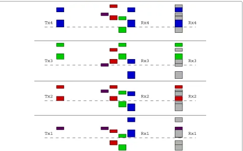
direct and cross-links of (4), we obtain the deterministic model of interference channel. The input-output relation-ship is shown in the left part of Fig. 1, for the convenience of demonstration; the input levels are also shifted byαk,k
positions so that the inputs and outputs of the direct links are at the same levels. For the cross-link from transmit-ter jto receiveri, the shifting is thus changed toαi,j−
αj,j instead of αi,j. At each receiver, the direct-link
out-puts (signal) and the cross-link outout-puts (interference) are added together when they are on the same level, and the outputs below the noise level are discarded. Rather than the normal integer addition, modulo-2 addition is chosen here to avoid interaction between different levels. This is a simplified operation only applied in the deterministic model. In Gaussian channels, the addition of signals and
interference will produce carry-over problem, which will be addressed in Section 3.
2.2 Alignment in amplitude space
From the left part of Fig. 1, we can see that, if all the transmit levels are active, there must be collisions between signals and interference. To avoid collision, only part of the transmit levels can be active. Therefore, we need to study an optimal active level assignment algorithm to avoid collision and simultaneously maximize the network sum rate.
In theK-user deterministic interference channel, each active level conveys one bit. To avoid collision, each level at the receiver side should be occupied either by a signal bit or by an interference bit. Actually, this interference bit can be a modulo-2 addition of several interference bits, since it is not necessary to decode each of these inter-ference bits separately. In order to leave as many receive levels as possible “free” for reception of signal bits, it will be advantageous if multiple interference bits fall on one receive level. This is the principle of interference align-ment in amplitude space: the alignalign-ment of interference saves amplitude levels for desired signals and thus the throughput can be increased.
The optimal active level assignment problem can be formulated as
wherebk,lindicates whether thel-th transmit level of user
k is active or not, and l = l+ (αk,j− αj,j). When the
level is active,bk,l = 1, otherwisebk,l = 0. The second
constraint means that, if thel-th level of userjinterferes with thel-th level of userkthrough the cross-link,bk,land
bj,lcan not be “1” simultaneously; otherwise, the received
signal is not decodable. Since the transmit levels of user jare shifted by αk,j− αj,j positions when they arrive at
receiverk, thel-th transmit level of userjwill fall on level l+(αk,j−αj,j)at receiverk. Thus,whenl=l+(αk,j−αj,j),
bj,l is an interference to bk,l, and these two bits are not
allowed to be “1” simultaneously.
If there is another user i and its l-th level bi,l also
interfere withbk,l, similarly there will be a constraint that
bk,l+bi,l ≤1. However, we do not restrict the summation
of the interference bits, i.e.,bj,l+bi,lcan be any value even
when they fall on the same level at receiverk. If bothbi,l
andbj,lare active, wherel+(αk,i−αi,i)=l+(αk,j−αj,j)=
l, the constraint can still be satisfied as long asbk,l=0.
Fig. 1An example of deterministic interference channel with three users, where the matrix of{αi,j}is [ 4 2 3; 4 4 4; 0 4 4]. The left part shows the input-output relationship and the right part shows the active level assignment result, where solid lines denote signal links and dashed lines denote interference links
linear programming (LP)-based branch-and-bound algo-rithm [39]. The algoalgo-rithm searches for an optimal solution to the binary integer programming problem by solving a series of LP relaxation problems, in which the binary inte-ger requirement on the variables is replaced by the weaker constraint 0≤bk,l≤1.
One example of the optimized results is shown in the right part of Fig. 1. We can see the features of an amplitude-aligned interference network. From the trans-mitter side, each user has different active level assign-ment, and the active levels may not be contiguous. At the receiver side, several interference links might be aligned on one level, and the interference levels might be above, below, or interlaced with the signal levels.
3 Interference alignment in Gaussian channels
The deterministic channel model described above assumes that all SNRs and INRs are integer on the log scale, i.e., the signals fall exactly on the evenly spaced “lev-els” at the receiver. In Gaussian channels, however, this assumption is not valid. In the following, we will address the interference alignment problem taking into account arbitrary SNR and INR values.
Given the link quality matrix, at each receiver, there is one collision pattern in amplitude space, i.e., part of
the desired signal may collide with part of the interfer-ence. The collision pattern changes at different receivers because they experience different SNR and INRs. The layer partitioning requires to find all the possible colli-sion areas in the amplitude space between the signals and interference.
The layer partitioning procedure is shown in Fig. 2. For each userk, the SNR of the direct channel isγk,k, which is
represented by a bar with a height logγk,kat the
transmit-ter side. At receiverk, there areKbars representing theK received signals. Their relative positions in the amplitude space are affected by the corresponding SNRs and INRs. For useri’s bar, the upper and lower boundaries are logγk,i
and logγk,i−logγi,i, respectively. If the bar of userj,j =k,
overlaps with the bar of userk, both bars are split (sep-arated into different layers) at the intersecting boundary positions. Repeating these processes at every receiver, we will obtain at most 2K(K−1)layers for each transmit sig-nal. The results shown in Fig. 2 are obtained when a group of random values are set for, i.e.,
10 log10= ⎡ ⎢ ⎢ ⎣
7.43 3.47 1.57 8.69 7.42 6.51 4.16 3.92 3.45 7.18 9.40 2.53 8.84 9.58 4.50 8.33
⎤ ⎥ ⎥
Fig. 2From left to right: the transmit signal before layer partitioning, the received signals of different users, and the layer partitioning results
After layer partitioning, userkhasLklayers in the
trans-mitter side, and the upper and lower boundaries of thel-th layer are respectivelyPk,l andPk,l−1. Thus, thel-th layer
has an amplitude space represented byρk,l = Pk,l/Pk,l−1. Assume now that we have a layered transmission scheme where the bits in the highest layers are decoded first. Thus, the decisions of the current layer can at most be disturbed by as-yet undecoded layers, i.e., the layers with a lower power than the current one. Thus, ρk,l can be
viewed as a signal-to-interference ratio (SIR) of this layer. If Shannon capacity achieved transmission were used, Rk,l = 1/2 log(1+ρk,l)bits could be transmitted in this
layer. Considering the encoding and decoding methods to be introduced in Section 4, which have a rate loss of at most 0.5 bit, we useRk,l =1/2 log(ρk,l).
As in the deterministic model of Section 2, some ers must be inactive to avoid collision between the lay-ered signals of different users. We can still apply the binary integer programming algorithm to search the opti-mal active layer assignment, so that the total through-put can be maximized. In Gaussian channels, since each layer has different amplitude space, the objective func-tion should be weighted by the transmission capability of each layer, i.e.,Rk,l. The optimization problem is therefore
formulated as
max
K
k=1
Lk
l=1
Rk,lbk,l,
s.t.bk,l∈ {0, 1},
bk,l+bj,l ≤1, ∀j,k,landj =k (7)
wherebk,ldenotes the transmit state of layerlof userk.
When this layer is active,bk,l=1, otherwisebk,l=0. The
second constraint is to avoid collision between the desired signal and interferences. If thel-th layer of userj inter-feres with thel-th layer of userkthrough the cross-link, bk,landbj,l can not be “1” simultaneously. Unlike in the
deterministic model, the relation betweenlandldoes not have an explicit expression here.
Fig. 3From left to right: the transmit layer assignment, the received signals of different users, and the desired signal and undesired interference, where the grey blocks denote the superimposed interference
Different from the deterministic channels, the addition of two layers of interference has a higher signal level than any of the two layers, i.e., the carry-over problem must be considered. The active layers assigned through (7) might be tightly connected, which means that at one receiver the lower boundary of an upper signal layer might be the upper boundary of a lower interference layer. If the inter-ference layer is superimposed from two or more users, the carry-over part might collide with the upper signal layer. Therefore, at the bottom of the signal layer, we need to reserve some amplitude space for the carry-over inter-ference. In practice, this can be done by retaining the transmit power and reducing the data rate of the upper signal layer.
For example, at receiverk, suppose there are two inter-ference layers below the signal layerl. One is from user j, and the upper boundary is h2k,jPj,l; the other is from
useri, and the upper boundary ish2k,iPi,l. Thus, the lower
boundary of the signal layer l at the transmitter side is changed into
˜
Pk,l−1=max Pk,l−1,
h2k,jPj,l+h2k,iPi,l
h2k,k
, (8)
where the first term inside the maximum operation is the upper boundary of the(l−1)-th layer of userk, and the second term is the sum power of two layers of interference divided by the square of the direct-link channel gain. If the second term is larger, at receiver k, the lower boundary of the l-th layer of user k is changed from h2k,kPk,l−1 to
h2k,jPj,l +h2k,iPi,l. The reserved space is at most 3 dB and
thus the data rate loss is at most 0.5 bit. When the lower layer is occupied by the superimposed interference from Kusers, the reserved space is at most 10 log10(K)dB and the data rate loss is at most 1/2 log(K)bits. This data rate loss can be neglected compared to the increasing sum rate when SNR goes to infinity.
4 Implementation by multi-level nested lattice
codes
interferences, instead of decoding the interference signals one by one.
A latticeis ann-dimensional discrete subgroup of the Euclidean spaceRnunder vector addition. Thus, ifλ
1and
λ2are in, their sum and difference are also in. A lattice
2is said to be nested in a lattice1if2 ⊆ 1. The
lattice1is often referred to as a fine lattice and2as a
coarse lattice. A nested lattice codeLis the set of all points of the fine lattice that are within the fundamental Voronoi regionV2of the coarse lattice, i.e.,L=1∩V2.
For any two powersPa ≥Pb≥0, [40] shows that there
exist nestedn-dimensional lattices2 ⊆ 1, asn→ ∞,
their second momentσ2(2)=Pa,σ2(1)=Pb, and the
coding rate ofLsatisfies
R= 1
volume of Voronoi regionVi.
In [41], it is shown that nested lattice codes can achieve the capacity of point-to-point AWGN channels. In [42], a doubly nested lattice coding scheme was provided which can approach the capacity region of a two-way relay chan-nel within 0.5 bit. Reference [43] provides a practical implementation scheme for nested lattice coding, where turbo coding and trellis shaping (multidimensional quan-tization) are involved. Due to space limitation, we refer the interested reader to [44, 45] for the detailed definitions and general construction methods of lattice codes.
For the transmitterk, define a sequence of nested lattice k,0,k,1,· · ·,k,Lk, wherek,Lk ⊆ · · · ⊆ k,1 ⊆ k,0.
The second moment ofk,lisσ2(k,l)=Pk,l.
The codebook used by levell is a nested lattice code
Ck,l=k,l−1∩Vk,l, and the codewordck,l∈Ck,l. The rate
The transmitted signal of userkis the summation of all the codewords where the corresponding layers are active, i.e.,
The received signal at userkis the superposition of the signals from all transmitted users, which is
rk= K
j=1
hk,jsj+vk. (12)
However, it has decoding problem if we just useLk
lay-ers of nested lattice code for each user k. As shown in Fig. 3, the received signals and interference are in lay-ers and might be interlaced. If an interference layer is
above a signal layer, we need first to decode and cancel the interference layer before decoding the signal layer. If the interference from two or more users exist above a signal layer, we need to decode the superimposed interference irrespective of whether the boundaries of interference layers are aligned or not.
For example, at receiverk, above the l-th signal layer there is a superimposed interference layer that is added by the l-th layer of userj and thel-th layer of useri. The upper boundary of the signal layer ish2k,kPk,l, and the
lower boundaries of two interference layers are respec-tivelyh2k,jPj,l−1andh2k,iPi,l−1, where we haveh2k,jPj,l−1≥
Through adjusting the transmit powers of related layers, we can makehk,jj,l−1andhk,ii,l−1aligned at receiver
k, but it is impossible to simultaneously makehk,jj,l−1
andhk,ii,l−1aligned at another receiverk.
To solve this problem, we just require a relationship that hk,jj,l−1 and hk,ii,l−1 are nested at receiver k. Since
h2k,jPj,l−1 ≥ h2k,kPk,l and h2k,iPi,l−1 ≥ h2k,kPk,l, we can
add a level of nested lattice j,m with second moment
h2k,k/h2k,jPk,lat transmitterj, and add a level of nested
lat-can then be decoded. Similarly, at receiverk, if there are interference layers above the signal layers and the inter-ference layer is superimposed from multiple users, we can add more levels of nested lattice at the transmitter side to make the received interference codewords nested.
After these level insertion operations, the nested lattice levels increase toL+k for userk, but the number of active signal layers does not change. The decoded codeword of thel-th signal layer is
ˆ
and then taken a modulus operation relative to lattice k,l. The quantization operation is to mitigate the
inter-ference of lower layers, and the modulus operation can mitigate the interference of the upper layers by decoding and cancelation.
5 Simulation results
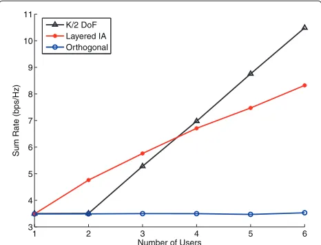
We first study the performance of the layered IA scheme in deterministic interference channels and compare it with the orthogonal transmission scheme, and a virtual IA scheme where each user can achieve 1/2 DoF of the channel.
The virtual IA scheme demonstrated here is not a real transmission scheme. Since currently there is only DoF result for the layered IA transmission with arbitrary channel coefficients, we use this result to provide a per-formance benchmark of the achievable sum rate. In the virtual IA scheme, we compute the achievable rate of each user based on its SNR and without taking into account the impact of interference, and the sum rate of K users is obtained by the summation of each user’s achievable rate and divided by 2. This method reflects the fact that each user can exploit 1/2 DoF of the channel. If there is only one user, this user will use the full DoF of the chan-nel. The sum rate obtained in this way is labeled as “K/2 DoF” in Figs. 4 and 5. When SNR approaches infinity, the DoF result can reflect the upper bound of channel capac-ity. However, in moderate SNR values the achieved rate obtained from the DoF may have large difference with the capacity.
In deterministic models, the logarithmic channel gains are integer. We set the logarithmic SNRs and INRs as random integer selected from 1∼6. InK-user orthogo-nal transmission scheme, each user occupies 1/K of the time or frequency resources no matter what the SNRs and INRs are. The corresponding results are shown in Fig. 4. We can see that the sum rate of the virtual IA scheme lin-early increases with the number of users when K ≥ 2, but its performance is not the best for all cases. In two-user or three-two-user interference channels, the proposed
1 2 3 4 5 6
3 4 5 6 7 8 9 10 11
Number of Users
Sum Rate (bps/Hz)
K/2 DoF Layered IA Orthogonal
Fig. 4Compare the average sum rate of the layered IA scheme with the virtual IA scheme and the orthogonal transmission scheme in deterministic interference channels
1 1.5 2 2.5 3 3.5 4 4.5 5
6 8 10 12 14 16 18
Number of Users
Sum Rate (bps/Hz)
K/2 DoF Layered IA Orthogonal
Fig. 5Compare the average sum rate of the layered IA scheme with the virtual IA scheme and the orthogonal transmission scheme in Gaussian interference channels
layered IA scheme can achieve higher sum rate. Accord-ing to the optimization process in Section 2, the active level assignment is not an equal distribution among users. By contrast, the user with better channel conditions (e.g., large SNR and small INR) might be assigned more active levels to maximize the sum rate. Hence, when the number of users is not too much, the optimized level assignment scheme outperforms the scheme that each user exploits one half of the channel resource. In interference channels with more than three users, the virtual IA scheme will gradually dominate the performance due to the advantage that each user can exploit 1/2 DoF of the channel. No mat-ter how many users exist, the achieved sum rate of the orthogonal transmission scheme always keeps unchanged. The comparisons of the layered IA scheme and other two schemes in Gaussian channels are shown in Fig. 5, where the SNRs and INRs are all randomly selected from 0∼40 dB. Because of the carry-over effect, in moder-ate SNR levels, the achieved sum rmoder-ate of the layered IA scheme grows not as fast as in deterministic channels. Yet with two and three users, the layered IA scheme still outperforms the virtual IA scheme. Similarly, with more users the virtual IA scheme will dominate the perfor-mance again since its achieved sum-rate keeps linearly increased.
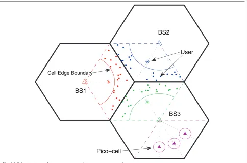
BS1
BS2
BS3
Cell Edge Boundary
User
Pico−cell
Fig. 6Cellular deployment for homogeneous and heterogeneous networks
No matter in homogeneous or heterogeneous network deployments, we consider single-antenna configurations for BSs and users. This is to show the performance gain purely provided by the amplitude-space sharing scheme. The inter-site distance of the macro-BSs is 500 m, and the cell radius of pico-cell is 30 m. The transmit powers of macro-BS and pico-BS are 46 and 30 dBm, respectively. The path loss models for macro-BS to users and for pico-BS to users are chosen according to the 3GPP channel model [46]
PL1 = 15.3+37.6 log10(D),
PL2 = 30.6+36.7 log10(D),
whereDis the distance between the BS and user. The cell-edge SNR is set as 5 dB, and small-scale Rayleigh fading is also considered.
We first observe the performance of layered IA scheme in three-cell homogeneous networks. Although the pro-posed scheme can be applied with any number of cells, for the homogeneous deployment, the interferences to one cell are mainly from the adjacent two cells. The outer cells with further distance only contribute noisy interference and will not affect the layer participation and alignment
1000 120 140 160 180 200 220 2
4 6 8 10 12 14
BS−User Distance / Cell−Edge Boundary
Sum Rate (bps/Hz)
Layered IA, Symmetric Layered IA, Random FFR, Symmetric FFR, Random
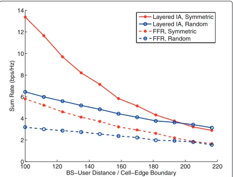
Fig. 7Compare the average sum rates of the layered IA scheme and the FFR scheme in three-cell homogeneous networks
rate achieved in this scenario can be greater than that in symmetric distribution scenario. The reason is that ran-dom user distribution diverges the SNR and INR values, which also creates more opportunities to assign active layers.
The performance of the layered IA scheme in hetero-geneous networks is evaluated in Fig. 8, where 1∼3 pico-cells coexisting with one macro-cell are considered. In this kind of deployment, the macro-user is randomly dis-tributed in one sector of the macro-cell, as shown in Fig. 6, and there is also one pico-user randomly distributed in each pico-cell. The layered IA scheme demonstrates great potential in this scenario, and the performance gain keeps increasing along with more coexisting pico-cells. When the distance between the pico-BS and macro-BS changes,
50 100 150 200
4 6 8 10 12 14 16
Distance between Macro−BS and Pico−BS
Sum Rate (bps/Hz)
Layered IA, 3−pico Layered IA, 2−pico Layered IA, 1−pico Orthogonal−Based
Fig. 8Compare the average sum rates of the layered IA scheme in heterogeneous networks with different number of pico-cells
the sum rate varies in different patterns with different number of pico-cells. With only one pico-cell coexists with the macro-cell, it constitutes a two-user interfer-ence channel. Although the position of the macro-user is random, the interference scenarios that the pico-user experienced have certain rules to follow. When the pico-cell moves from pico-cell center to pico-cell edge, the interference caused by the macro-BS to the pico-user will change from strong to weak. In this kind of two-user interference chan-nel, the sum rate is higher both in strong interference or weak interference scenarios and is lower when the inter-ference has a similar strength with the signal. From the explanation in Section 3, we also know that the strong interference can share the upper amplitude space above the signal layer, and the weak interference can share the lower amplitude space below the signal layer. If the inter-ference has a similar strength as the signal, both the signal and the interference will reduce their occupied amplitude space for coexisting. In the simulation results of Fig. 8, the average sum rate for one pico-cell configuration is a concave curve, which subsidizes our analysis.
When the number of pico-cells increases to two and three, the sum rate curves are monotonically increasing. The reason behind this phenomenon is the interference among the pico-cells. In the simulations, the SNRs and INRs of all links are computed from the transmit power and the simulated channel gains, which include the large-scale path loss and small-large-scale Rayleigh fading. When the pico-cells are close to the macro-BS, as can be seen from Fig. 6, the distances between these pico-cells are shorter. In this scenario, not only the interference from macro-BS to pico-users is stronger but also the interference from pico-BSs to pico-users. When the pico-cells move away from the macro-BS, the interference from macro-BS and pico-BS are all weaker. As observed in Section 3, the layer partitioning and assignment are complicated in the multi-user case. Although we do not provide an explicit analysis, the simulation results show that the average sum rate will increase when we move the pico-cells towards the macro-cell edge.
6 Conclusions
rate grows with the number of users, and with two or three users, the proposed scheme outperforms the vir-tual scheme that each user occupies half of the channel resource. In practical cellular systems, the layered IA scheme provided evident rate gain over the orthogonal-based transmission schemes and showed great potential to mitigate the complicated co-tier and cross-tier interfer-ences in heterogeneous networks.
Competing interests
The authors declare that they have no competing interests.
Acknowledgements
This work was supported by the National Natural Science Foundation of China under Grant 61371077.
Received: 10 November 2014 Accepted: 14 May 2015
References
1. S-P Yeh, S Talwar, G Wu, N Himayat, K Johnsson, Capacity and coverage enhancement in heterogeneous networks. IEEE Wireless Commun. Mag. 18(3), 32–38 (2011)
2. J Hoydis, M Kobayashi, M Debbah, Green small-cell networks. IEEE Veh. Technol. Mag.6(1), 37–43 (2011)
3. D Lopez-Perez, I Guvenc, G de la Roche, M Kountouris, TQS Quek, J Zhang, Enhanced intercell interference coordination challenges in
heterogeneous networks. IEEE Wireless Commun. Mag.18(3), 22–30 (2011)
4. S Chatzinotas, B Ottersten, in19th International Conference on Telecommunications (ICT). Cognitive interference alignment between small cells and a macrocell (Jounieh, Lebanon, 23 April 2012) 5. Y Jeong, H Shin, MZ Win, inProc. IEEE 22nd International Symposium on
Personal Indoor and Mobile Radio Communications (PIMRC). Interference rejection combining in two-tier femtocell networks (Toronto, Canada, 11 September 2011)
6. W Shin, W Noh, K Jang, H-H Choi, Hierarchical interference alignment for downlink heterogeneous networks. IEEE Trans. Wireless Commun.11(12), 4549–4559 (2012)
7. M Maso, M Debbah, L Vangelista, A distributed approach to interference alignment in OFDM-based two-tiered networks. IEEE Trans. Veh. Technol. 62(5), 1935–1949 (2013)
8. VR Cadambe, SA Jafar, Interference alignment and degrees of freedom of theK-user interference channel. IEEE Trans. Inf. Theory.54(8), 3425–3441 (2008)
9. T Gou, SA Jafar, Degrees of freedom of theKuserM×NMIMO interference channel. IEEE Trans. Inf. Theory.56(12), 6040–6057 (2010) 10. AS Motahari, AK Khandani, Capacity bounds for the Gaussian interference
channel. IEEE Trans. Inf. Theory.55(2), 620–643 (2009) 11. X Shang, G Kramer, B Chen, A new outer bound and the noisy
interference sum-rate capacity for Gaussian interference channels. IEEE Trans. Inf. Theory.55(2), 689–699 (2009)
12. VS Annapureddy, VV Veeravalli, Gaussian interference networks: sum capacity in the low-interference regime and new outer bounds on the capacity region. IEEE Trans. Inf. Theory.55(7), 3032–3050 (2009) 13. VS Annapureddy, VV Veeravalli, Sum capacity of MIMO interference
channels in the low interference regime. IEEE Trans. Inf. Theory.57(5), 2565–2581 (2011)
14. AB Carleial, A case where interference does not reduce capacity. IEEE Trans. Inf. Theory.21(5), 569–570 (1975)
15. H Sato, The capacity of the Gaussian interference channel under strong interference. IEEE Trans. Inf. Theory.27(6), 786–788 (1981)
16. X Shang, HV Poor, Capacity region of vector Gaussian interference channels with generally strong interference. IEEE Trans. Inf. Theory.58(6), 3472–3496 (2012)
17. Y Tian, S Lu, C Yang, Macro-pico amplitude-space sharing with optimized Han-Kobayashi coding. IEEE Trans. Commun.61(10), 4404–4415 (2013)
18. TS Han, K Kobayashi, A new achievable rate region for the interference channel. IEEE Trans. Inf. Theory.27(1), 49–60 (1981)
19. RH Etkin, DNC Tse, H Wang, Gaussian interference channel capacity to within one bit. IEEE Trans. Inf. Theory.54(12), 5534–5562 (2008) 20. SA Jafar, Interference alignment - a new look at signal dimensions in a
communication network. Found. Trends Commun. Inf. Theory.7(1), 1–134 (2011)
21. VR Cadambe, SA Jafar, S Shamai, Interference alignment on the deterministic channel and application to fully connected Gaussian interference networks. IEEE Trans. Inf. Theory.55(1), 269–274 (2009) 22. RH Etkin, E Ordentlich, The degrees-of-freedom of theK-user Gaussian
interference channel is discontinuous at rational channel coefficients. IEEE Trans. Inf. Theory.55(11), 4932–4946 (2009)
23. Y Wu, S Shamai, S Verdu, inIEEE International Symposium on Information Theory. Degrees of freedom of the interference channel: a general formula (Saint-Petersburg, Russia, 31 July 2011)
24. AS Motahari, S Oveis-Gharan, M Maddah-Ali, AK Khandani, Real interference alignment: exploiting the potential of single antenna systems. IEEE Trans. Inf. Theory.60(8), 4799–4810 (2014)
25. SH Mahboubi, M Hussain, AS Motahari, AK Khandani, Layered interference alignment: achieving the total DoF of MIMO X channels.
arXiv:1412.7188 (2014)
26. WM Schmidt,Diophantine Approximation. (Springer, Berlin, 1980) 27. GH Hardy, EM Wright,An Introduction to the Theory of Numbers. (Oxford
Science, Oxford, 2003)
28. M Hussain, J Levesley, The metrical theory of simultaneously small linear forms. Funct. Approx. Comment. Math.48(2), 167–181 (2013) 29. M Hussain, S Kristensen, Metrical results on systems of small linear forms.
Int. J. Number Theory.9(3), 769–782 (2013)
30. V Beresnevich, D Dickinson, S Velani, RC Vaughan, Diophantine approximation on planar curves and the distribution of rational points. Ann. Math.166(2), 367–426 (2007)
31. V Beresnevich, Rational points near manifolds and metric Diophantine approximation. Ann. Math.175(1), 187–235 (2012)
32. D Badziahin, S Harrap, M Hussain, An inhomogeneous Jarník type theorem for planar curves. arXiv:1503.04981 (2015)
33. SA Jafar, S Vishwanath, Generalized degrees of freedom of the symmetric GaussianKuser interference channel. IEEE Trans. Inf. Theory.56(7), 3297–3303 (2010)
34. A Jafarian, S Vishwanath, Achievable rates forK-user Gaussian interference channels. IEEE Trans. Inf. Theory.58(7), 4367–4380 (2012) 35. O Ordentlich, U Erez, On the robustness of lattice interference alignment.
IEEE Trans. Inf. Theory.59(5), 2735–2759 (2013)
36. G Bresler, A Parekh, DNC Tse, The approximate capacity of the many-to-one and one-to-many Gaussian interference channels. IEEE Trans. Inf. Theory.56(9), 4566–4592 (2010)
37. AS Avestimehr, SN Diggavi, DNC Tse, Wireless network information flow: a deterministic approach. IEEE Trans. Inf. Theory.57(4), 1872–1905 (2011) 38. D Tse, It’s easier to approximate. Inf. Theory Soc. Newslett.60(1), 6–11
(2010). (Plenary talk presented at the ISIT 2009)
39. LA Wolsey,Integer Programming. (John Wiley & Sons, New York, 1998) 40. W Nam, S-Y Chung, YH Lee, Capacity of the Gaussian two-way relay
channel to within 1/2 bit. IEEE Trans. Inf. Theory.56(11), 5488–5494 (2010) 41. U Erez, R Zamir, Achieving12log(1+SNR)on the AWGN channel with
lattice encoding and decoding. IEEE Trans. Inf. Theory.50(10), 2293–2314 (2004)
42. Y Tian, D Wu, C Yang, AF Molisch, Asymmetric two-way relay with doubly nested lattice codes. IEEE Trans. Wireless Commun.11(2), 694–702 (2012) 43. U Erez, S Brink ten, A close-to-capacity dirty paper coding scheme. IEEE
Trans. Inf. Theory.51(10), 3417–3432 (2005)
44. JH Conway, NJA Sloane,Sphere Packings, Lattices and Groups. (3rd, ed.) (Springer, New York, 1998)
45. U Erez, S Litsyn, R Zamir, Lattices which are good for (almost) everything. IEEE Trans. Inf. Theory.51(10), 3401–3416 (2005)
![Fig. 1 An example of deterministic interference channel with three users, where the matrix of {αi,j} is [ 4 2 3; 4 4 4; 0 4 4]](https://thumb-us.123doks.com/thumbv2/123dok_us/947747.1115707/4.595.60.539.87.364/fig-example-deterministic-interference-channel-users-matrix-ai.webp)